US1065939A - Water-meter. - Google Patents
Water-meter. Download PDFInfo
- Publication number
- US1065939A US1065939A US38852707A US1907388527A US1065939A US 1065939 A US1065939 A US 1065939A US 38852707 A US38852707 A US 38852707A US 1907388527 A US1907388527 A US 1907388527A US 1065939 A US1065939 A US 1065939A
- Authority
- US
- United States
- Prior art keywords
- chamber
- measuring chamber
- opening
- main case
- case
- Prior art date
- Legal status (The legal status is an assumption and is not a legal conclusion. Google has not performed a legal analysis and makes no representation as to the accuracy of the status listed.)
- Expired - Lifetime
Links
- XLYOFNOQVPJJNP-UHFFFAOYSA-N water Substances O XLYOFNOQVPJJNP-UHFFFAOYSA-N 0.000 description 18
- OKTJSMMVPCPJKN-UHFFFAOYSA-N Carbon Chemical compound [C] OKTJSMMVPCPJKN-UHFFFAOYSA-N 0.000 description 8
- 229910002804 graphite Inorganic materials 0.000 description 8
- 239000010439 graphite Substances 0.000 description 8
- 238000005192 partition Methods 0.000 description 8
- 239000012530 fluid Substances 0.000 description 6
- 239000000463 material Substances 0.000 description 6
- 230000009471 action Effects 0.000 description 5
- 238000010276 construction Methods 0.000 description 3
- 230000006378 damage Effects 0.000 description 3
- 239000004615 ingredient Substances 0.000 description 3
- 239000000203 mixture Substances 0.000 description 3
- NINIDFKCEFEMDL-UHFFFAOYSA-N Sulfur Chemical compound [S] NINIDFKCEFEMDL-UHFFFAOYSA-N 0.000 description 2
- 229920001971 elastomer Polymers 0.000 description 2
- 239000011819 refractory material Substances 0.000 description 2
- 239000000126 substance Substances 0.000 description 2
- 229960005349 sulfur Drugs 0.000 description 2
- 229910052717 sulfur Inorganic materials 0.000 description 2
- 235000001508 sulfur Nutrition 0.000 description 2
- 239000011593 sulfur Substances 0.000 description 2
- BSYNRYMUTXBXSQ-UHFFFAOYSA-N Aspirin Chemical compound CC(=O)OC1=CC=CC=C1C(O)=O BSYNRYMUTXBXSQ-UHFFFAOYSA-N 0.000 description 1
- 229910000906 Bronze Inorganic materials 0.000 description 1
- 244000286663 Ficus elastica Species 0.000 description 1
- 239000000899 Gutta-Percha Substances 0.000 description 1
- RRHGJUQNOFWUDK-UHFFFAOYSA-N Isoprene Chemical compound CC(=C)C=C RRHGJUQNOFWUDK-UHFFFAOYSA-N 0.000 description 1
- 240000000342 Palaquium gutta Species 0.000 description 1
- 208000027418 Wounds and injury Diseases 0.000 description 1
- 239000003831 antifriction material Substances 0.000 description 1
- 239000011324 bead Substances 0.000 description 1
- 230000008901 benefit Effects 0.000 description 1
- 238000009835 boiling Methods 0.000 description 1
- 239000010974 bronze Substances 0.000 description 1
- 150000001875 compounds Chemical class 0.000 description 1
- KUNSUQLRTQLHQQ-UHFFFAOYSA-N copper tin Chemical compound [Cu].[Sn] KUNSUQLRTQLHQQ-UHFFFAOYSA-N 0.000 description 1
- 230000000694 effects Effects 0.000 description 1
- 238000005868 electrolysis reaction Methods 0.000 description 1
- 229910000286 fullers earth Inorganic materials 0.000 description 1
- -1 graphite Chemical class 0.000 description 1
- 229920000588 gutta-percha Polymers 0.000 description 1
- 238000007654 immersion Methods 0.000 description 1
- 208000014674 injury Diseases 0.000 description 1
- 230000002452 interceptive effect Effects 0.000 description 1
- 230000001050 lubricating effect Effects 0.000 description 1
- 230000007246 mechanism Effects 0.000 description 1
- 238000000034 method Methods 0.000 description 1
- 238000000465 moulding Methods 0.000 description 1
- 230000002093 peripheral effect Effects 0.000 description 1
- 229920001195 polyisoprene Polymers 0.000 description 1
- 230000008439 repair process Effects 0.000 description 1
- 239000007787 solid Substances 0.000 description 1
- 230000003245 working effect Effects 0.000 description 1
Images

Classifications
-
- G—PHYSICS
- G01—MEASURING; TESTING
- G01F—MEASURING VOLUME, VOLUME FLOW, MASS FLOW OR LIQUID LEVEL; METERING BY VOLUME
- G01F3/00—Measuring the volume flow of fluids or fluent solid material wherein the fluid passes through the meter in successive and more or less isolated quantities, the meter being driven by the flow
- G01F3/02—Measuring the volume flow of fluids or fluent solid material wherein the fluid passes through the meter in successive and more or less isolated quantities, the meter being driven by the flow with measuring chambers which expand or contract during measurement
- G01F3/04—Measuring the volume flow of fluids or fluent solid material wherein the fluid passes through the meter in successive and more or less isolated quantities, the meter being driven by the flow with measuring chambers which expand or contract during measurement having rigid movable walls
- G01F3/06—Measuring the volume flow of fluids or fluent solid material wherein the fluid passes through the meter in successive and more or less isolated quantities, the meter being driven by the flow with measuring chambers which expand or contract during measurement having rigid movable walls comprising members rotating in a fluid-tight or substantially fluid-tight manner in a housing
- G01F3/12—Meters with nutating members, e.g. discs
-
- Y—GENERAL TAGGING OF NEW TECHNOLOGICAL DEVELOPMENTS; GENERAL TAGGING OF CROSS-SECTIONAL TECHNOLOGIES SPANNING OVER SEVERAL SECTIONS OF THE IPC; TECHNICAL SUBJECTS COVERED BY FORMER USPC CROSS-REFERENCE ART COLLECTIONS [XRACs] AND DIGESTS
- Y10—TECHNICAL SUBJECTS COVERED BY FORMER USPC
- Y10T—TECHNICAL SUBJECTS COVERED BY FORMER US CLASSIFICATION
- Y10T74/00—Machine element or mechanism
- Y10T74/19—Gearing
- Y10T74/19642—Directly cooperating gears
- Y10T74/19679—Spur
Definitions
- PatentedJuly 1, 1913 PatentedJuly 1, 1913.
- the general objects of the invention are to provide a water meter or measuring device adapted to operate under allconditions of temperature and service andwith water at all fluid temperatures-whether boiling'hot or cold and to provide a nut-ating'piston for this purposeadaptedfor use in hot or cold water without injury.
- a further object is to prov-idea gear trainfor the control of the registering mechanism which is characterized by improved efficiency and-durability in use, and which byv slight adjustment of bearings can be made to last for an indefinite period of time with unabated usefulness.
- a further-object is to. rovid'e' a direct path for the circulation of to fluid: through the geartrain and in this manner to attain immunityfor the gearing from the action of electrolysis or fromgalvanic action incidentt'o'their immersion in dead or lifeless-water such as accumulates aboutthe gearing inthe main case in the ordinary forms of 'construc tiom
- a further object is to provide formsfiof one assembled. mass, and hence increase the accessibility 0t all. parts and: theiradaptability to adjustment and repair.. This form of construction also. permits reversal of the motor in any position without interfering" with its use.
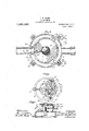
- Figure 1 a central vertical section of the improved device
- Fig. 2 is a side view of the measuring or piston chamber showing inlet and outlet orifices therein, and radial partition
- Fig. 3 is a horizontal transverse section through the main case and piston chamber
- In these views 1 is the main case of a substantially dome shape and having integral therewith the lower half 2 of' the register box, and an inte ral stufling'box' 3 for the stufling box spin le 4% and stulling box gear
- the lower'endof this case 1 is provided with oppositely located inletand outlet openings 5 and 6 respectively.
- the measuringor piston chamber 7 forms the support forthe crown frame 8 and bearing plate 9 mounted there on, upon which, the gear train T :omprising pinion and. spur reducing gears 10, 11, 12, 13-, 14, 15, 16 and 17 are mounted. By means of this train of gears the speed of revolution of the piston is reduced to the exact degree desired.
- These parts consisting of the measuring chamber and crown frame and bearing plate, are secured together by means of'lugs 18 and screws 19, and a single bottom plate ZGdQlItLCillllJlY secured to the main case by bolts 21 forms a complete assembled body, and the opening in the main case which receives the measuring chamber is tapered: outwardly and the engaging portions of'thc measuring chamber are similarly tapered at 22 so as to form.
- the bottom is detachably secured by bolts 21 as shown. In this manner the working-parts arestrongly and durably supported and connected together and the device will operate as well upside down as right side up.
- the bottom cover 20 is preferably breakable so that the measuring chamber-- showing relative location of the inlet and outlet orifices;
- Fig. 4 is a plan view of the controlling gear train and the crown frame ⁇ and bearing plate arranged for the support i of the same;
- Fig. 5 is a vertical sectional ;view of the crown frame and bearing plate ishowingone of the screw threaded spindles, adapted to aiford adjustment for the renewal-of the bearing surfaces.
- the entire structure may be mounted upon base members 40 by means of bolts 41 which pass through said base members and through lugs 42 carried by the main case 1.
- Nuts 43 are threaded upon .take its passage up over the measuring chamber and down into the inlet opening 25 in this chamber. Thence the water will pass through this chamber and after operating the disk valve P will pass out the outlet opening 27 and main outlet 6.
- a radial partition 28 separates the inlet and outlet openings in this chamber.
- a complete circulation through the gear train T is thus formed which prevents the water surrounding the gears from becoming dead and prevents the setting up of any galvanic or electrolytic action therein which ordinarily is the source of gradual disintegration of the gears. The water itself will notcorrode them since they are made of bronze.
- the disk shaped piston P is peculiar in being made very wide between striking surfaces, and hence has a wide bearing surface upon the circular walls of the chamber. Also to prevent danger of breakage of the edges of the radial slot X in the disk upon the partition a ball P is inserted in the opposite edge of the disk, which is designed to travel in a vertical groove 29 in the wall of the chamber and hence keep the disk from rubbing on the partition.
- the body of the disk is also novel in being formed of materials ,or a substance which while being rigid is also not hard enough to produce any. great degree of friction. This disk isflformed' of a composition containing graphite andpther refractory materials. It is also formed of material of a substance which is only.
- the bottom 20 is not attached to the measuring chamber but when attached to the main case secures the measuring chamber and all the working parts in place.
- the disk piston including the ball and disk is composed largely of a self lubricating non-frictional compound, such as graphite, which is also refractory in character.
- a main case having an opening in its bottom and oppositely located inlet and outlet openings and provided with vertically arranged ribs spaced partition. separating said openings in themeasuring chamber, said. ribs in said; main case and. measuring chamber forming a passagewhereby the fluid is. conducted over said .measuring chamber, substantially as described.
- a substantially dome shaped main case having an opening in. its bottom, a measuring chamber therein, a crown plate and depressible hearing. plate mounted. upon said measuring chamber, a controlling gear -train thereon, a breakable bottom plate for the main case upon which. said measuring chamber and crown plate, bearing plate and gear train are assembled, and an integral st-ufling box and portion of a register box upon said main case, substantially as described.
- a substantially ⁇ dome shaped main case having oppositely located inlet and outlet openings and having: a bottom opening said case being provided with vertical ribs on its in:
- a measuring chamber inserted in said bottom opening in said chamber and provided with ribs on its outer surface corresponding in location and taper with the ribs on the said chamber, said chamber having an outlet opening registering with the outlet opening inthe said main case, and passing through one of said ribs on the chamber, .said chamber having also an inlet opening adjacentto said outlet opening and opposite to the inlet opening in the case, a disk piston in said chamber a controlling gear train mounted upon said measuring chamber and bearing supports for said train assembled upon said .chamber, said piston having operative connection with said gear train, the said ribs upon said case and chamber being spaced to provide a passage for the fluid passing through said meter, leading from the inlet opening insaid case through said gear train to the inlet opening in the chamber, substantially as described.
- a main case having an integral register box portion and an integral stufling box thereon, and provided with opposite openings for inlet and outlet respectively and with a bottom opening, a measuring chamber therein, a crown plate and depressible bearing plate upon said measuring chamber and a gear train thereon, a bottom plate for said cas'e adapted; toclose said opening, said chamber, gear-train and crown and bearing plates being removable from said casing in one assembled'.
- a measuring chamber operatively connected with said controllingv gear train, and bear-- ing spindles for the gears in said gear train, the-spindles passing through the depressible portion of said bearing plate being screw threaded and provided with beads engaging said depressible plate as and for the purpose set forth,
- a main case of substantially dome shape provided with oppositely placed inlet and outlet openings and a bottom opening, a measuring chamber a disk and piston therein adapted to be inserted into said bottom opening, crown and depressible bearing plates, and a control gear train thereon assembled upon said measuring chamber and removable therewith, the said piston being made of refractory material only affected by great extremes of temperature and having a broad bearing surface.
- a water meter in a water meter the combination with a main case closed at the upper end and having an opening in the bottom and opposite inlet and outlet openings, of a measuring chamber adapted to be inserted in the bottom, and provided with closely adjacent inlet and outlet openings, said main case and measuring chamber having registering ribs tapering on their meeting edges, and forming a tapered bearing for saidmeasuring chamber, a breakable cover for said opening and means for detachably securing said cover to said casing, substantially as described.
- a .water meter the combination with a main case, having an opening in its bottom and oppositely located inlet and outlet openings, of a measuring case, and a piston therein, and a controlling gear train mounted upon said measuring chamber and secured thereto, said measuring chamber and attached gear train and piston being insertibleinto said case through said bottom opening, said measuring chamber having closely adjacent inlet and outlet openings, a vertical partition in said case on each side of the inlet opening therein and a vertical partition in said case separating .the inlet and outlet openings in said measuring chamber, 7 chamher in said case and tapered bearing sura tapered socket for said measurin faces registering therewith on said chamber and a breakable cover for said opening detachably secured to saidcase, the said. vertical partitions being so spaced. as to di- 4 rectthe incoming fluid upwardly and through the controlling gear, directl to the inlet passage in said measuring 0 amber, substantially as described.
- a Water meter the combination. with a main case provided with a bottom opening and with oppositely located inlet I and outlet openings, of a measuring chamber adaptedto be inserted into said case through said bottom opening, registering tapered ribs upon said main case and measuri'ng chamber,'whereby tapered socketand bearing surfaces are formed in the main case and measuring chamber, and a cover for said bottom opening in said case and means for detachably securing said cover to said case, the said ribs being spaced to form a.v channel for fluid entering said inlet open ing, leading over said measuring chamber and the but-let passages from measuring chamber and main case passing through engaging ribs on said members, substantially as described.
- a main case having a bottom opening and 0p-.
Landscapes
- Physics & Mathematics (AREA)
- Fluid Mechanics (AREA)
- General Physics & Mathematics (AREA)
- A Measuring Device Byusing Mechanical Method (AREA)
Description
F. W. HANKS.
WATER METER.
APPLICATION FILED AUG. 14. 1907.
1,065,939. Patented July 1,1913.
2 SHEETSSHEET 1.
EWI-
F. W. HANKS."
WATER METER.
APPLIOATION FILED AUG. 14, 1907.
Patented July 1, 1913.
2 SHEETS-SHEET 2.
Jigs
rREiJEnIcK w. BANKS; or CLEVELAND, c1110,
Specification ofiIiettei-s Patent.
PatentedJuly 1, 1913.
Applicatimflemhgustm,1.90:7. Serial No. 388,527.
To. all whom it may concern Be it known that I, Fnnonnron W. Hanna,
a citizen of the United.- States, residing at Cleveland, in. the county of Guyahoga and State of Ohio, haveinvented: new and useful- Improvements in Water -M'eters, of whiclrthe following is a specification.
The general objects of the invention are to provide a water meter or measuring device adapted to operate under allconditions of temperature and service andwith water at all fluid temperatures-whether boiling'hot or cold and to provide a nut-ating'piston for this purposeadaptedfor use in hot or cold water without injury..
A further object is to prov-idea gear trainfor the control of the registering mechanism which is characterized by improved efficiency and-durability in use, and which byv slight adjustment of bearings can be made to last for an indefinite period of time with unabated usefulness.
A further-object is to. rovid'e' a direct path for the circulation of to fluid: through the geartrain and in this manner to attain immunityfor the gearing from the action of electrolysis or fromgalvanic action incidentt'o'their immersion in dead or lifeless-water such as accumulates aboutthe gearing inthe main case in the ordinary forms of 'construc tiom A further object is to provide formsfiof one assembled. mass, and hence increase the accessibility 0t all. parts and: theiradaptability to adjustment and repair.. This form of construction also. permits reversal of the motor in any position without interfering" with its use.
Further objects are to provide a removable bottom which with all the inner parts can lee-bodily removedland which is adapted and arranged to break and release the work-- ing parts and prevent; the destruction of any part. ofthe meter except the bottom in case of excessive internal pressure as from the action. of frost.
The "b jects' further include improvementsin thesimplicity and 'unity in the construction of the meter andcomprise also the improvements in the construction of details and combination and arrangement of the various parts as hereinafter described, shown in: the accompanyin 1 drawings and specifically pointed out 1n t 1e claims.
In: the accompanying drawings, Figure 1 a central vertical section of the improved device; Fig. 2: is a side view of the measuring or piston chamber showing inlet and outlet orifices therein, and radial partition; Fig. 3 is a horizontal transverse section through the main case and piston chamber In these views 1 is the main case of a substantially dome shape and having integral therewith the lower half 2 of' the register box, and an inte ral stufling'box' 3 for the stufling box spin le 4% and stulling box gear The lower'endof this case 1 is provided with oppositely located inletand outlet openings 5 and 6 respectively. The measuringor piston chamber 7 forms the support forthe crown frame 8 and bearing plate 9 mounted there on, upon which, the gear train T :omprising pinion and. spur reducing gears 10, 11, 12, 13-, 14, 15, 16 and 17 are mounted. By means of this train of gears the speed of revolution of the piston is reduced to the exact degree desired. These parts, consisting of the measuring chamber and crown frame and bearing plate, are secured together by means of'lugs 18 and screws 19, and a single bottom plate ZGdQlItLCillllJlY secured to the main case by bolts 21 forms a complete assembled body, and the opening in the main case which receives the measuring chamber is tapered: outwardly and the engaging portions of'thc measuring chamber are similarly tapered at 22 so as to form. a tight fit therewith. The bottom is detachably secured by bolts 21 as shown. In this manner the working-parts arestrongly and durably supported and connected together and the device will operate as well upside down as right side up. The bottom cover 20 is preferably breakable so that the measuring chamber-- showing relative location of the inlet and outlet orifices; Fig. 4 is a plan view of the controlling gear train and the crown frame {and bearing plate arranged for the support i of the same; and Fig. 5 is a vertical sectional ;view of the crown frame and bearing plate ishowingone of the screw threaded spindles, adapted to aiford adjustment for the renewal-of the bearing surfaces.
and case will not be destroyed at a low degree of temperature.
' If desired, the entire structure may be mounted upon base members 40 by means of bolts 41 which pass through said base members and through lugs 42 carried by the main case 1. Nuts 43 are threaded upon .take its passage up over the measuring chamber and down into the inlet opening 25 in this chamber. Thence the water will pass through this chamber and after operating the disk valve P will pass out the outlet opening 27 and main outlet 6. A radial partition 28 separates the inlet and outlet openings in this chamber. A complete circulation through the gear train T is thus formed which prevents the water surrounding the gears from becoming dead and prevents the setting up of any galvanic or electrolytic action therein which ordinarily is the source of gradual disintegration of the gears. The water itself will notcorrode them since they are made of bronze.
By reference to the drawings particularly I Fig. 3 it will be seen that an important advantage is derived from the independent character and horizontal adjustability of the measuring chamber for the reason that the relative positions of the outlet openings in the measuring chamber and case can be adjusted so as to reduce the outlet opening if desired; which has the effect of lessening the strain upon the piston under very great pressure.
The disk shaped piston P is peculiar in being made very wide between striking surfaces, and hence has a wide bearing surface upon the circular walls of the chamber. Also to prevent danger of breakage of the edges of the radial slot X in the disk upon the partition a ball P is inserted in the opposite edge of the disk, which is designed to travel in a vertical groove 29 in the wall of the chamber and hence keep the disk from rubbing on the partition. The body of the disk, is also novel in being formed of materials ,or a substance which while being rigid is also not hard enough to produce any. great degree of friction. This disk isflformed' of a composition containing graphite andpther refractory materials. It is also formed of material of a substance which is only.
ing pipes sometimes backs up into the meter. Ordinarily meter valves formed of compositions containing rubber or guttapercha are liable to destruction from the ef- 'fects of heat thereon.
To provide means for removing the bearing surfaces of the gear spindles in the gear train two of the spindles or shafts. in the outer row at 30 and 31 are formed as screws. These screws have large heads 32 and 33 which rest upon the bearing plate and are inserted in the crown frame. When the inner sides of the bearing surfaces of these screws become Worn a fresh surface can be immediately supplied by turning the screws partially around in the crown frame. Another important result is also obtained' by this action viz. as the screws are turned their heads press down the outer portion 34 of the bearing plate and thereby press the inner surface of the central bearing 35 into contact with the central driving spindle 36. In this manner the bearings can be almost indefinitely renewed at pleasure and the utility of the device for all possible situations many of them diflicult of access eatly enhanced.
The bottom 20 is not attached to the measuring chamber but when attached to the main case secures the measuring chamber and all the working parts in place.
I believe myself to be the first to make the piston disk of anti-friction material which will be affected only by extreme degrees of heat and cold, or'is partially refractory.
I. am aware that disks for this invention have been made of vulcanite or hard rubher, but these disks are affected by heat and warped out of shape. Ma-ny materials are suitable for this purpose, but the specific composition does not pertain to the spirit of this invention.
The disk piston including the ball and disk is composed largely of a self lubricating non-frictional compound, such as graphite, which is also refractory in character.
Other ingredients are india rubber and sul fur, in sufiicient quantity to permit vulcanizing the whole into a solid mass. Other ingredients to give body to the piston may be powdered graphite, or fullers earth. If the graphite could be'compressed sufficiently to hold together, no rubber or sulfur, and vulcanizing would be required. Graphite is the only important ingredient. Many methods of molding and solidifying the same can be used. 7
Having described the invention what claim as new and desire to secure by Letters Patent is i 1. In a water meter, a main case, having an opening in its bottom and oppositely located inlet and outlet openings and provided with vertically arranged ribs spaced partition. separating said openings in themeasuring chamber, said. ribs in said; main case and. measuring chamber forming a passagewhereby the fluid is. conducted over said .measuring chamber, substantially as described.
2.. In combination inawater meter,a substantially dome shaped: main case having an opening in. its bottom, a measuring chamber therein, a crown plate and depressible hearing. plate mounted. upon said measuring chamber, a controlling gear -train thereon, a breakable bottom plate for the main case upon which. said measuring chamber and crown plate, bearing plate and gear train are assembled, and an integral st-ufling box and portion of a register box upon said main case, substantially as described.
In combination in a water meter, a substantially \dome shaped main case, having oppositely located inlet and outlet openings and having: a bottom opening said case being provided with vertical ribs on its in:
terior walls,.the inner faces of said ribs being upwardly tapered and said. inlet opening between said ribs, a measuring chamber inserted in said bottom opening in said chamber and provided with ribs on its outer surface corresponding in location and taper with the ribs on the said chamber, said chamber having an outlet opening registering with the outlet opening inthe said main case, and passing through one of said ribs on the chamber, .said chamber having also an inlet opening adjacentto said outlet opening and opposite to the inlet opening in the case, a disk piston in said chamber a controlling gear train mounted upon said measuring chamber and bearing supports for said train assembled upon said .chamber, said piston having operative connection with said gear train, the said ribs upon said case and chamber being spaced to provide a passage for the fluid passing through said meter, leading from the inlet opening insaid case through said gear train to the inlet opening in the chamber, substantially as described.
4. In combination in a water meter, a main case, having an integral register box portion and an integral stufling box thereon, and provided with opposite openings for inlet and outlet respectively and with a bottom opening, a measuring chamber therein, a crown plate and depressible bearing plate upon said measuring chamber and a gear train thereon, a bottom plate for said cas'e adapted; toclose said opening, said chamber, gear-train and crown and bearing plates being removable from said casing in one assembled'. body means for securing said parts together and means for securing said parts to said main case, substantially as described.
5. In a water meter, a measuring chamber, a controlling gear train mounted thereon, a crown plate and an upper bearing plate having a. depressible portion and securedto said measuring chamber in which crown and bearing plate said gear train is mounted, a piston: in said chamber operatively connected with said controllingv gear train, and bear-- ing spindles for the gears in said gear train, the-spindles passing through the depressible portion of said bearing plate being screw threaded and provided with beads engaging said depressible plate as and for the purpose set forth,
6. In combination with the controlling gear train of a water meter, a crown plate and an upper bearing plate having a de pressible portion, and spindles for. the gears of said train having screw threads inserted in said; crown plate and heads engaging said depressible plate, substantially as described.
7-. In a water meter, a main case of substantially dome shape provided with oppositely placed inlet and outlet openings and a bottom opening, a measuring chamber a disk and piston therein adapted to be inserted into said bottom opening, crown and depressible bearing plates, and a control gear train thereon assembled upon said measuring chamber and removable therewith, the said piston being made of refractory material only affected by great extremes of temperature and having a broad bearing surface.
8. In a water meter the combination with a main case closed at the upper end and having an opening in the bottom and opposite inlet and outlet openings, of a measuring chamber adapted to be inserted in the bottom, and provided with closely adjacent inlet and outlet openings, said main case and measuring chamber having registering ribs tapering on their meeting edges, and forming a tapered bearing for saidmeasuring chamber, a breakable cover for said opening and means for detachably securing said cover to said casing, substantially as described.
9. In a .water meter, the combination with a main case, having an opening in its bottom and oppositely located inlet and outlet openings, of a measuring case, and a piston therein, and a controlling gear train mounted upon said measuring chamber and secured thereto, said measuring chamber and attached gear train and piston being insertibleinto said case through said bottom opening, said measuring chamber having closely adjacent inlet and outlet openings, a vertical partition in said case on each side of the inlet opening therein and a vertical partition in said case separating .the inlet and outlet openings in said measuring chamber, 7 chamher in said case and tapered bearing sura tapered socket for said measurin faces registering therewith on said chamber and a breakable cover for said opening detachably secured to saidcase, the said. vertical partitions being so spaced. as to di- 4 rectthe incoming fluid upwardly and through the controlling gear, directl to the inlet passage in said measuring 0 amber, substantially as described.
10. In a Water meter, the combination. with a main case provided with a bottom opening and with oppositely located inlet I and outlet openings, of a measuring chamber adaptedto be inserted into said case through said bottom opening, registering tapered ribs upon said main case and measuri'ng chamber,'whereby tapered socketand bearing surfaces are formed in the main case and measuring chamber, and a cover for said bottom opening in said case and means for detachably securing said cover to said case, the said ribs being spaced to form a.v channel for fluid entering said inlet open ing, leading over said measuring chamber and the but-let passages from measuring chamber and main case passing through engaging ribs on said members, substantially as described.
11. In a water meter, in combination, a main case having a bottom opening and 0p-.
by a self-lubricating material containing positeinlet and outlet openings, a measuring chamber the controlling gear train and supporting bearings assembled thereon, and
inlet opening in said measuring chamber,
the said outlet openings from said measuring chamber and main case passing between 7 pairs of engaging ribs and a coverfor said bottom opening, secured to said main case, substantially as described.
12. In a disk water-meter, the combination with the disk, of a bearing'ball attached thereto consisting of a self-lubricating material containing graphite. p
13. In a disk water-meter, a disk having its peripheral frictional surface formed graphite. 14. In a disk water-meter, a disk having a slot, the frictional surface of the slot being formed of, a self-lubricating material con taining graphite. In testimony whereof I hereunto set my hand this 12th day of August, 1907.
FREDERICK W. HANKS. In presence of-- WM. M. MONROE, P. R. CANrmLD.
Priority Applications (1)
| Application Number | Priority Date | Filing Date | Title |
|---|---|---|---|
| US38852707A US1065939A (en) | 1907-08-14 | 1907-08-14 | Water-meter. |
Applications Claiming Priority (1)
| Application Number | Priority Date | Filing Date | Title |
|---|---|---|---|
| US38852707A US1065939A (en) | 1907-08-14 | 1907-08-14 | Water-meter. |
Publications (1)
| Publication Number | Publication Date |
|---|---|
| US1065939A true US1065939A (en) | 1913-07-01 |
Family
ID=3134182
Family Applications (1)
| Application Number | Title | Priority Date | Filing Date |
|---|---|---|---|
| US38852707A Expired - Lifetime US1065939A (en) | 1907-08-14 | 1907-08-14 | Water-meter. |
Country Status (1)
| Country | Link |
|---|---|
| US (1) | US1065939A (en) |
Cited By (2)
| Publication number | Priority date | Publication date | Assignee | Title |
|---|---|---|---|---|
| US2688874A (en) * | 1948-03-25 | 1954-09-14 | Rockwell Mfg Co | Fluid meter |
| US4594890A (en) * | 1982-08-03 | 1986-06-17 | Baker Jr Hugh M | Fluid flow measuring device |
-
1907
- 1907-08-14 US US38852707A patent/US1065939A/en not_active Expired - Lifetime
Cited By (2)
| Publication number | Priority date | Publication date | Assignee | Title |
|---|---|---|---|---|
| US2688874A (en) * | 1948-03-25 | 1954-09-14 | Rockwell Mfg Co | Fluid meter |
| US4594890A (en) * | 1982-08-03 | 1986-06-17 | Baker Jr Hugh M | Fluid flow measuring device |
Similar Documents
| Publication | Publication Date | Title |
|---|---|---|
| US1990423A (en) | Valve | |
| US1827470A (en) | Reversible check valve and cut-off | |
| USRE14455E (en) | hanks | |
| US1160864A (en) | Glass-drawing apparatus. | |
| US2296542A (en) | Spindle packing for meters and the like | |
| US935329A (en) | Valve. | |
| US739215A (en) | Water-meter. | |
| US535641A (en) | Disk water-meter | |
| US1481663A (en) | Valve | |
| US1903074A (en) | Meter | |
| US3203238A (en) | Compound meter | |
| US1460471A (en) | Liquid meter | |
| US1458965A (en) | Liquid meter | |
| US150611A (en) | Improvement in liquid-meters | |
| US1871912A (en) | Operating piston for liquid meters | |
| US969286A (en) | Water-meter. | |
| US1675523A (en) | Indicating and recording nonreturn valve | |
| US856244A (en) | Disk meter. | |
| US818430A (en) | Water-meter. | |
| US998853A (en) | Water-meter intermediate gearing. | |
| US1276482A (en) | Valve. | |
| US434995A (en) | Archibald j | |
| US1192189A (en) | Water-meter. | |
| US25660A (en) | Hydrant | |
| US744802A (en) | Grain-drill. |