US10659081B2 - Preprogrammed data recovery - Google Patents
Preprogrammed data recovery Download PDFInfo
- Publication number
- US10659081B2 US10659081B2 US15/846,242 US201715846242A US10659081B2 US 10659081 B2 US10659081 B2 US 10659081B2 US 201715846242 A US201715846242 A US 201715846242A US 10659081 B2 US10659081 B2 US 10659081B2
- Authority
- US
- United States
- Prior art keywords
- data
- code information
- error correction
- data group
- majority
- Prior art date
- Legal status (The legal status is an assumption and is not a legal conclusion. Google has not performed a legal analysis and makes no representation as to the accuracy of the status listed.)
- Active, expires
Links
- 238000011084 recovery Methods 0.000 title description 33
- 230000015654 memory Effects 0.000 claims abstract description 150
- 238000012937 correction Methods 0.000 claims abstract description 96
- 238000000034 method Methods 0.000 claims abstract description 65
- 230000001172 regenerating effect Effects 0.000 claims description 12
- 238000012545 processing Methods 0.000 claims description 7
- 238000004519 manufacturing process Methods 0.000 description 21
- 238000010586 diagram Methods 0.000 description 8
- 238000005476 soldering Methods 0.000 description 8
- 230000004888 barrier function Effects 0.000 description 5
- 230000006872 improvement Effects 0.000 description 5
- 230000002411 adverse Effects 0.000 description 4
- 238000013500 data storage Methods 0.000 description 4
- 230000008569 process Effects 0.000 description 4
- 238000004088 simulation Methods 0.000 description 4
- 229910000679 solder Inorganic materials 0.000 description 4
- 230000008901 benefit Effects 0.000 description 3
- 230000015556 catabolic process Effects 0.000 description 3
- 230000001010 compromised effect Effects 0.000 description 3
- 239000000463 material Substances 0.000 description 3
- 230000008929 regeneration Effects 0.000 description 3
- 238000011069 regeneration method Methods 0.000 description 3
- 239000000523 sample Substances 0.000 description 3
- 238000012360 testing method Methods 0.000 description 3
- 230000008859 change Effects 0.000 description 2
- 238000007796 conventional method Methods 0.000 description 2
- 238000006731 degradation reaction Methods 0.000 description 2
- 230000000694 effects Effects 0.000 description 2
- 230000014759 maintenance of location Effects 0.000 description 2
- 230000004075 alteration Effects 0.000 description 1
- 238000003491 array Methods 0.000 description 1
- 230000009286 beneficial effect Effects 0.000 description 1
- 230000015572 biosynthetic process Effects 0.000 description 1
- 238000010276 construction Methods 0.000 description 1
- 230000008878 coupling Effects 0.000 description 1
- 238000010168 coupling process Methods 0.000 description 1
- 238000005859 coupling reaction Methods 0.000 description 1
- 238000001514 detection method Methods 0.000 description 1
- 238000012986 modification Methods 0.000 description 1
- 230000004048 modification Effects 0.000 description 1
- 238000004806 packaging method and process Methods 0.000 description 1
- 238000006467 substitution reaction Methods 0.000 description 1
Images


Classifications
-
- H—ELECTRICITY
- H03—ELECTRONIC CIRCUITRY
- H03M—CODING; DECODING; CODE CONVERSION IN GENERAL
- H03M13/00—Coding, decoding or code conversion, for error detection or error correction; Coding theory basic assumptions; Coding bounds; Error probability evaluation methods; Channel models; Simulation or testing of codes
- H03M13/29—Coding, decoding or code conversion, for error detection or error correction; Coding theory basic assumptions; Coding bounds; Error probability evaluation methods; Channel models; Simulation or testing of codes combining two or more codes or code structures, e.g. product codes, generalised product codes, concatenated codes, inner and outer codes
- H03M13/2906—Coding, decoding or code conversion, for error detection or error correction; Coding theory basic assumptions; Coding bounds; Error probability evaluation methods; Channel models; Simulation or testing of codes combining two or more codes or code structures, e.g. product codes, generalised product codes, concatenated codes, inner and outer codes using block codes
-
- G—PHYSICS
- G06—COMPUTING; CALCULATING OR COUNTING
- G06F—ELECTRIC DIGITAL DATA PROCESSING
- G06F11/00—Error detection; Error correction; Monitoring
- G06F11/07—Responding to the occurrence of a fault, e.g. fault tolerance
- G06F11/08—Error detection or correction by redundancy in data representation, e.g. by using checking codes
- G06F11/10—Adding special bits or symbols to the coded information, e.g. parity check, casting out 9's or 11's
- G06F11/1008—Adding special bits or symbols to the coded information, e.g. parity check, casting out 9's or 11's in individual solid state devices
- G06F11/1048—Adding special bits or symbols to the coded information, e.g. parity check, casting out 9's or 11's in individual solid state devices using arrangements adapted for a specific error detection or correction feature
-
- G—PHYSICS
- G06—COMPUTING; CALCULATING OR COUNTING
- G06F—ELECTRIC DIGITAL DATA PROCESSING
- G06F11/00—Error detection; Error correction; Monitoring
- G06F11/07—Responding to the occurrence of a fault, e.g. fault tolerance
- G06F11/08—Error detection or correction by redundancy in data representation, e.g. by using checking codes
- G06F11/10—Adding special bits or symbols to the coded information, e.g. parity check, casting out 9's or 11's
- G06F11/1008—Adding special bits or symbols to the coded information, e.g. parity check, casting out 9's or 11's in individual solid state devices
- G06F11/1068—Adding special bits or symbols to the coded information, e.g. parity check, casting out 9's or 11's in individual solid state devices in sector programmable memories, e.g. flash disk
-
- G—PHYSICS
- G06—COMPUTING; CALCULATING OR COUNTING
- G06F—ELECTRIC DIGITAL DATA PROCESSING
- G06F11/00—Error detection; Error correction; Monitoring
- G06F11/07—Responding to the occurrence of a fault, e.g. fault tolerance
- G06F11/16—Error detection or correction of the data by redundancy in hardware
- G06F11/1666—Error detection or correction of the data by redundancy in hardware where the redundant component is memory or memory area
- G06F11/167—Error detection by comparing the memory output
-
- G—PHYSICS
- G11—INFORMATION STORAGE
- G11C—STATIC STORES
- G11C29/00—Checking stores for correct operation ; Subsequent repair; Testing stores during standby or offline operation
- G11C29/52—Protection of memory contents; Detection of errors in memory contents
Definitions
- the disclosure herein relates generally to memory, and, more particularly to recovering preprogrammed data in such memory after operations that can compromise the validity of the preprogrammed data.
- preprogrammed data can be stored in nonvolatile memory devices during manufacturing, where the preprogrammed data is later retrieved by a processor or other entity in a system that includes the nonvolatile memory devices and used for operations such as startup or initialization.
- preprogrammed data can be stored in nonvolatile memory embedded on the chip and then later used by logic circuitry or other circuitry on the chip when the chip is later included in a system.
- Preprogramming data in nonvolatile memory during manufacturing is relatively straightforward as the conditions are present to enable such programming during testing operations such as wafer probe or burn-in.
- preprogrammed data can be put in jeopardy during subsequent manufacturing operations.
- soldering a finished integrated circuit onto a printed circuit board using reflow soldering techniques can expose the integrated circuit to temperatures on the order of 260° C. Such elevated temperatures can cause degradation of stored memory states, thereby potentially corrupting the preprogrammed data stored earlier in the manufacturing process.
- Magnetoresistive memory devices store information with magnetic states that result in different device resistances.
- the resistance across a magnetic tunnel junction (MTJ) depends on the relative magnetic states of the magnetic layers within the memory cell.
- MTJ magnetic tunnel junction
- other memory devices exist that store data in ways that can be compromised by exposure to heat or other adverse conditions presented by the manufacturing processes.
- other forms of resistive memory store data based on the state of the materials included within the memory device, where the state of those materials can be impacted by exposure to the heat associated with reflow soldering.
- One example includes state change memory in which data is stored based on whether a layer of material is in an amorphous state. While the effects of such exposure to heat may not cause total loss of data in the memory affected, some subset of the bits included in the memory can be compromised, thereby resulting in undesirable errors in the overall data set.
- FIG. 1 is a block diagram showing distributed redundant data storage in a memory in accordance with exemplary embodiments
- FIG. 2 is a block diagram showing application of a majority voting scheme in accordance with exemplary embodiments
- FIGS. 3 and 4 are flow charts illustrating methods for recovering preprogrammed data stored in memory cells in accordance with exemplary embodiments
- FIG. 5 is a block diagram showing circuitry used for preprogrammed data recovery in accordance with exemplary embodiments
- FIG. 6 is a block diagram showing data sets and data groups used in the recovery of preprogrammed data in accordance with another exemplary embodiment
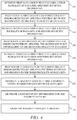
- FIG. 7 is a flow chart illustrating a method for recovering data stored in memory cells in accordance with another exemplary embodiment.
- FIG. 8 is a block diagram of a system that performs recovery of preprogrammed data in accordance with another exemplary embodiment.
- Non-volatile memory examples of which include magnetoresistive memory, state-change memory, FLASH memory, and ferroelectric memory is non-volatile in the sense that once a data bit is stored in a memory cell, removal of power to the memory will not result in the data being lost.
- a memory may be preprogrammed during manufacturing, where the information stored on the memory is later used after the memory is placed within a system.
- the pre-programming performed during manufacturing may occur during testing (e.g., wafer probe or burn-in) when the memory is already being exercised, and therefore a separate programming operation is unnecessary. Such preprogramming can help reduce overall system manufacturing costs.
- Such preprogrammed data can sometimes be lost due to operations that occur after such preprogramming.
- exposure to magnetic fields, high temperatures, or other conditions can disrupt the magnetic state of the free portions of the memory cells.
- the high temperatures associated with soldering operations when a device is mounted to a printed circuit board can result in the loss of such preprogrammed data.
- solder reflow operations expose the device to temperatures on the order of 260° C., which can lower the energy barrier of the free layer and allow it to unintentionally change state, thereby corrupting the information stored in the free layer.
- the memory cells in a magnetic memory device can be designed in order to increase the robustness with which such memory cells are able to retain data during manufacturing operations that expose such memory devices to adverse conditions.
- the data retention capability of the memory cell and the ease with which the state of the memory cell can be changed during a normal write operations to the memory cell.
- the thickness or composition of the various layers making up the magnetic tunnel junction in a magnetic memory cell can be changed in order to allow for better data retention when exposed to magnetic fields or heat.
- the thicker layers typically result in a larger energy barrier, such that switching the free layer of the magnetic tunnel junction requires a higher voltage. During normal operation, having a higher energy barrier and requiring higher switching voltages can result in earlier breakdown of the memory cells and less reliable writing operations.
- the structure of the magnetic memory cells can be designed in order to achieve reasonably reliable data storage through the manufacturing process (a tolerable raw bit error rate (BER)) while preserving the general ease with which the free layer can be switched during normal operation.
- Designing the magnetic memory cells in such a manner presents the risk that some data bits will be compromised during manufacturing based on the raw BER.
- Techniques are presented herein to allow such preprogrammed data to be reliably recovered such that the memory cells can be engineered to have desirable switching characteristics during normal operation. As discussed in additional detail below, such techniques include storing multiple copies of the data in different portions of individual memory devices, or in different memory devices within a system. Majority voting schemes and the use of error correction codes are used to reliably recover the preprogrammed data which can then be used by the system in which the memory storing the preprogrammed data is included.
- FIG. 1 illustrates memory 100 that stores three data groups 110 , 120 , and 130 .
- the memory 100 is a single integrated circuit memory device such as an MRAM memory device.
- the memory 100 is a group of memory devices where each memory device is on a separate integrated circuit or chip.
- Each of the data groups 110 , 120 , and 130 is originally preprogrammed in the memory to represent duplicate copies of the same data group. In other words, there are multiple copies of the data stored in the memory 100 to provide redundancy.
- each of the data groups 110 , 120 , and 130 is identical in terms of the bits included within the data group. While FIG.
- 1 shows three copies of the data group being stored within the memory 100
- other embodiments store more than three copies of the same data group in different locations within the memory 100 .
- 5, 7, 9, 11, 13, 15, or more copies of the same data group can be stored within the memory 100 .
- Each data group includes a data portion that includes a plurality of data bits as well as a set of error correction code (ECC) information, where the ECC information in each data group is determined based on the plurality of data bits included in that data group and can be used to correct errors in the plurality of data bits included in that data group.
- ECC error correction code
- data group 110 includes data 112 and ECC information 114 .
- data group 120 includes data 122 and ECC information 124
- data group 130 includes data 132 and ECC information 134 .
- bits included in the data groups 110 , 120 , and 130 are initially identical after being preprogrammed, following subsequent manufacturing operations that expose the memory 100 to adverse conditions, some of the bits within one or more of the data groups can be corrupted such that the stored bits within a single data group may not correspond to the bits originally programmed.
- FIG. 2 illustrates an example of a majority voting scheme used to generate a majority data group 140 from three data groups 110 , 120 , and 130 that were originally stored as redundant copies of the data group attempting to be recovered.
- each of the data groups 110 , 120 , and 130 has a single bit error in the bits making up the data group.
- the last bit 115 in the ECC information has switched from a “0” to a “1”.
- the last bit 125 in the data portion has switched from a “1” to a “0”.
- the second bit 135 in the data portion has switched from a “0” to a “1”.
- the majority voting scheme compares each bit in each data group with the corresponding bits in the other data groups and selects a bit value for each bit location corresponding to the majority state of the bits in the different data groups. In the case of three data groups, if at least two of the bits are the same, that is the majority state of the bits in that location. For example, the majority state for the last bit in the ECC portion of the data group is a “0” based on both data groups 120 and 130 having a “0” in that bit location while data group 110 has a “1” in that location. The error in data group 110 is outvoted by the corresponding bits in data groups 120 and 130 .
- majority voting schemes there are many logic circuits that can implement majority voting schemes.
- a processor performs the operations associated with majority voting. While majority voting provides a way to compare multiple redundant copies of the same data groups stored in memory, the error correction provided by such majority voting schemes is often not sufficient to provide the level of reliability needed to recover important data associated with system startup or other system-critical operations.
- the ECC information included for each data group can also be leveraged to correct errors that have occurred. As discussed below, such ECC information can be leveraged either before a majority voting scheme is applied.
- the ECC information included with each data group can be considered local ECC information and may be the same type of ECC information stored with data in the non-volatile memory during normal operations.
- FIGS. 3 and 4 are flow charts that illustrate exemplary embodiments of methods of recovering preprogrammed data stored in memory cells, where, in some embodiments, the data is stored in the orientation of the magnetic moment of the free layers in magnetic memory devices.
- the operations included in the flow charts may represent only a portion of the overall process used in recovering the data.
- the following description of the methods in FIGS. 3 and 4 may refer to elements mentioned above in connection with FIGS. 1 and 2 .
- methods may include any number of additional or alternative tasks, the tasks shown in FIGS. 3 and 4 need not be performed in the illustrated order unless specified otherwise, and the methods may be incorporated into a more comprehensive procedure or process having additional functionality not described in detail herein.
- one or more of the tasks shown in FIGS. 3 and 4 can be omitted from an embodiment as long as the intended overall functionality remains intact.
- FIG. 3 illustrates a flow chart of a method for recovering preprogrammed data stored in memory cells in which majority voting precedes ECC correction.
- the preprogrammed data is data stored in nonvolatile memory cells during manufacturing operations such as wafer probe or burn-in. While some embodiments preprogram multiple redundant copies of the data in multiple locations within a single memory device (e.g. in different rows, banks, or arrays within the memory device), in other embodiments multiple redundant copies of the data are stored in separate memory devices (e.g. different chips).
- a first data group is retrieved from memory.
- the first data group includes a first plurality of data bits in a first set of ECC information.
- a second data group is retrieved, where the second data group includes a second plurality of data bits and a second set of ECC information.
- the second data group can be stored in a different array or different location within the same array within a single memory device, or in other embodiments the second data group is stored on a different integrated circuit.
- a third data group that includes a third plurality of data bits in a third set of ECC information is retrieved.
- each of the first, second, and third data groups represents a redundant copy of the data group originally stored as preprogrammed data.
- any additional data groups are retrieved at 216 .
- a majority data group is generated from the data groups retrieved from memory.
- the majority data group generated at 218 is generated using a majority voting scheme such as that described with respect to FIG. 2 .
- the individual bits in each of the data groups that have been retrieved from memory are compared with their corresponding bits in the other data groups in a majority voting scheme in order to arrive at a majority data group where each bit within the majority data group represents the result of the majority voting performed for that particular bit location.
- the bit is determined based on a majority voting scheme using a corresponding bit from each of the first, second, and third pluralities of data bits as well as any corresponding bits from any additional data groups retrieved at 216 .
- each bit in the set of ECC information in the majority data group is determined based on a majority voting scheme using a corresponding bit from each of the first, second, and third sets of ECC information as well as any corresponding bits in any additional data groups retrieved at 216 .
- the majority data group will include a plurality of data bits and a set of ECC information.
- the data group 140 shown in FIG. 2 is representative of a majority data group generated using the data groups 110 , 120 , and 130 retrieved from the memory 100 .
- a recovered data set is regenerated using the majority data group by applying the set of ECC information in the majority data group to the plurality of data bits in the majority data group to correct any errors detected.
- the ECC information included in the majority data group is used to detect and correct any errors within the data bits in the majority data group. This additional level of error detection and correction helps to further reduce the effect of any errors that may have occurred to bits in the redundant copies of the preprogrammed data during operations that occur following such preprogramming.
- the ECC information stored with each of the data groups can include a variety of different error correction information corresponding to different error correction schemes that are known in the art.
- the ECC information includes at least one parity bit, where parity bits are used to represent even or odd parity of the plurality of data bits within the data group.
- the ECC information includes Hamming code information, including one or more of Hamming code corresponding to single error correction based on a 128-bit word length, single error correction based on a 64-bit word length, double error correction corresponding to 128-bit word length, and double error correction corresponding to a 64-bit word length.
- Parity bits and Hamming codes are ECC techniques that are often used in conjunction with data storage and retrieval during normal memory operations, and such ECC techniques can be referred to as first-level ECC techniques.
- first-level ECC techniques can be readily implemented on the same integrated circuit with the data and, therefore, the data recovery using such ECC techniques can be done completely on-chip.
- aspects of the error correction using the ECC information are performed elsewhere in the system (i.e. off-chip).
- more complex error correction schemes such as Reed-Solomon coding, Bose-Chaudhuri-Hocquenghem (BCH) coding, Low-Density Parity-Check (LDPC) coding, or Memory Signal Processing (MSP) can be used to further enhance the recovery of the preprogrammed data.
- BCH Bose-Chaudhuri-Hocquenghem
- LDPC Low-Density Parity-Check
- MSP Memory Signal Processing
- Such more complex error correction schemes can be referred to as second-level ECC methods, where, in some embodiments, such methods are only used to recover the preprogrammed data and would not also be used with normal read/write operations in the memory.
- Such second-level ECC methods may be performed at a system level, where data is retrieved from multiple memory devices and the second-level ECC correction is performed by a central entity, such as a processor or other control circuit. While such second-level ECC schemes are more complex than the first-level ECC schemes mentioned above, if data integrity in a single integrated circuit system is important, the added complexity and cost of such second- level ECC schemes can be applied and used in a single chip system.
- a new set of ECC information for the recovered data set is generated at 222 .
- new ECC information for those data bits can be generated such that any subsequent errors to that data can be detected and corrected.
- the ECC information generated at 222 may be the same type of ECC information used to recover the data set at 220 , or some other ECC correction scheme.
- the recovered data set is stored in memory.
- the recovered data set is stored back into the same memory from which the redundant data groups were retrieved, whereas in other embodiments the recovered data set is stored into other memory, such as volatile memory or other nonvolatile memory.
- the preprogrammed data is rewritten into a location within the system allowing it to be used for its intended purpose. Such writing may be accomplished using normal writing techniques used to write data to the memory during normal operation.
- the preprogrammed data may correspond to boot code or other start-up information leveraged by a processor for system initialization.
- the processor may look to a specific memory location either in volatile or nonvolatile memory for that start-up data. As such, following recovery of the preprogrammed data the data can be stored in that location in order to enable the processor to perform the start-up operations.
- the data is stored in RAM (e.g. DRAM, SRAM, MRAM, etc.) using the writing techniques used to store data in such RAM during normal operations.
- the data recovery can be a one-time operation that avoids potential errors that can be created by operations such as solder reflow.
- FIG. 4 illustrates a flow chart of an alternate method for recovering preprogrammed data stored in memory cells.
- some embodiments preprogram multiple redundant copies of the data in multiple locations within a single memory device whereas in other embodiments multiple redundant copies of the data are stored in separate discrete memory devices.
- the method of FIG. 4 differs from that of FIG. 3 and that the ECC information stored with each data group is used to correct any detectable errors within the data group before a majority voting scheme is applied to the data in the data groups.
- a first data group is retrieved from the memory.
- the first data group includes a first plurality of data bits in a first set of ECC information.
- a first data set is regenerated by correcting any detectable errors within the first plurality of data bits using the first set of ECC information. For example, if the ECC information for the first plurality of data bits reveals a particular bit has inadvertently changed state, that error is corrected at this stage.
- the first data set corresponds to the first plurality of bits from the first data group with any ECC correctable errors corrected.
- a second data group is retrieved, where the second data group includes a second plurality of data bits and a second set of ECC information.
- the second data group can be stored in a different array or different location within the same array within a single memory device, or, in other embodiments, the second data group is stored on a different integrated circuit.
- a second data set is regenerated by correcting any detectable errors within the second plurality of data bits using the second set of ECC information.
- a third data group that includes a third plurality of data bits in a third set of ECC information is retrieved, and at 250 a third data set is regenerated by correcting any detectable errors within the third plurality of data bits using the third set of ECC information.
- each of the first, second, and third data groups represents a redundant copy of the data group originally stored as preprogrammed data. While the embodiment illustrated in FIG. 4 is presented in the context of three data groups, many more redundant copies of a particular data group can be stored in the memory and used together with the first three data groups in the recovery of the preprogrammed data.
- a majority data set is generated using a majority voting scheme for each bit in the data sets generated at 242 , 246 , and 248 .
- the resulting data sets are merged through majority voting to create a majority data set.
- Each bit in the majority data set is determined based on a majority vote amongst the corresponding bits in the different data sets. While the method of FIG. 3 perform such majority voting before doing ECC correction, the method of FIG. 4 first does the ECC correction and then performs majority voting to arrive at a majority data set.
- the majority data set determined at 252 corresponds to the recovered data set of FIG. 3 in that both are the end result of the error correction operations performed by the respective methods.
- a new set of ECC information is generated for the majority data set.
- the majority data set, and any newly generated ECC information corresponding to the majority data set is stored in memory.
- the end result data recovered using the method of FIG. 4 can be stored in the same memory chip(s) or memory array(s) from which the first, second, and third data groups were retrieved.
- the majority data set recovered can be stored in other memory for use by the various circuits included in the system in which the memory is being used.
- the ECC information included in the data groups retrieved in the method of FIG. 4 can include first-level ECC information or second-level ECC information as those terms were described above.
- the ECC information generated prior to storing the recovered majority data set can also include first- and/or second-level ECC information.
- FIG. 5 illustrates a block diagram of a system 260 in which preprogrammed data initially stored in the non-volatile memory array 280 is recovered for use within the system.
- the nonvolatile memory array 280 is an array of magnetic memory cells arranged in rows and columns on an integrated circuit with the rest of the system 260 .
- each magnetic memory cell includes a magnetic tunnel junction coupled in series with a selection transistor.
- the nonvolatile memory array 280 includes other types of memory cells that may be susceptible to degradation during manufacturing such that data recovery efforts can be beneficial in regenerating preprogrammed data stored in those memory cells.
- the nonvolatile memory array 280 is dispersed over multiple integrated circuits, where different portions of the nonvolatile memory array are included in each of those circuits.
- the nonvolatile memory array 280 could be a plurality of MRAM memory devices included on a printed circuit board.
- the preprogrammed data is initially stored at multiple locations in the nonvolatile memory array 280 , where the level of redundancy can be determined based on a desired bit error rate (BER) for the preprogrammed data within the system combined with an expected raw BER for the memory cells after manufacturing operations are complete. In order to achieve a lower bit error rate, more redundant copies of the preprogrammed data can be included in the nonvolatile memory array 280 .
- BER bit error rate
- Data recovery circuitry 290 is coupled to the nonvolatile memory array 280 .
- the data recovery circuitry 290 can include majority voting circuitry 292 that can perform the majority voting operations with respect to bits in the preprogrammed memory array such as those discussed above with respect to FIGS. 2-4 .
- data recovery circuitry 290 can include error correction circuitry 294 that is able to utilize ECC information stored within the groups of data corresponding to the preprogrammed data in order to correct any ECC-correctable errors within each of those data groups.
- the error correction processing performed by the error correction circuitry 294 can include first-level error correction operations and/or second-level error correction operations, where first-level error correction operations include error correction operations associated with parity bits or Hamming codes, and second-level error correction operations include more complex error correction operations such as Reed-Solomon coding, Bose-Chaudhuri-Hocquenghem (BCH) coding, Low-Density Parity-Check (LDPC) coding, or Memory Signal Processing (MSP).
- first-level error correction operations include error correction operations associated with parity bits or Hamming codes
- second-level error correction operations include more complex error correction operations such as Reed-Solomon coding, Bose-Chaudhuri-Hocquenghem (BCH) coding, Low-Density Parity-Check (LDPC) coding, or Memory Signal Processing (MSP).
- BCH Bose-Chaudhuri-Hocquenghem
- LDPC Low-Density Parity-Check
- the data recovery circuitry 290 is configured to retrieve multiple data groups from the nonvolatile memory array 280 , where each data group retrieved from the nonvolatile memory array 280 includes a plurality of data bits and a corresponding set of ECC information. Each data group represents the preprogrammed data, or a portion of the preprogrammed data, that is to be recovered. After retrieving the multiple data groups from memory, the data recovery circuitry 290 performs majority voting and error correction operations on the data groups to recover the preprogrammed data. After the preprogrammed data is recovered, the data recovery circuitry 290 can generate new ECC information for the data that has been recovered prior to storing the data and any new ECC information back to memory. The data recovery circuitry 290 can store the recovered data and accompanying ECC information back into the nonvolatile memory array 280 , or, in other embodiments, the data recovery circuitry 290 stores the recovered data in other memory 285 .
- logic circuitry 270 is included in the system 260 and utilizes the recovered preprogrammed data. Examples of embodiments that do not include logic circuitry 270 are standalone memory devices that are able to regenerate preprogrammed data prior and store that regenerated data for use by devices accessing the memory devices. In other embodiments, logic circuitry 270 is a processor or other processing entity that relies on the preprogrammed data for startup or other initialization operations.
- FIG. 6 corresponds to a block diagram that helps illustrate more complex techniques for recovering preprogrammed data stored in one or more memory devices.
- each data group in a plurality of data groups 310 - 312 includes a corresponding plurality of data bits 320 - 322 and a corresponding set of ECC information 330 - 332 .
- each of the data groups is stored on a separate memory device, whereas in other embodiments, some or all of the data groups are stored on the same memory device.
- Additional ECC information 340 and 350 can be stored on one of the same memory devices as the data groups 310 - 312 , or, in other embodiments, stored on one or more additional memory devices.
- a first-level ECC operation which, for example, may include parity or Hamming code correction, is performed for each of the data groups 310 - 312 based on the ECC information 330 - 332 included in each of those data groups.
- these first-level ECC correction operations can be performed on the individual memory devices.
- the first-level ECC correction is performed by a central circuit (e.g. a processor) rather than on the individual memory devices.
- the ECC information 330 - 332 corresponds to second-level, or a combination of first- and second-level, ECC information.
- ECC correction is performed based on different groupings of the bits within the plurality of data groups 310 - 312 .
- vertical slices of data such as the group 360 (illustrated using a dotted box) are combined and evaluated using a portion 362 of the ECC information 340 and 350 .
- the first ECC operations performed using the ECC information 330 - 332 corresponds to first-level ECC correction
- the second ECC operations performed using ECC information 340 and 350 corresponds to second-level ECC correction.
- Providing such two-level ECC correction and distributing the data across multiple integrated circuits can help to ensure better recovery of the preprogrammed data.
- all of the operations described with respect to FIG. 6 can be implemented on a single integrated circuit rather than in a distributed system that includes multiple integrated circuits.
- each of the data groups 310 - 312 may be stored in multiple locations within a single memory device and majority voting can be used to determine the majority data group for that memory device.
- the first ECC correction can be performed before or after such majority voting takes place on the memory device.
- FIG. 7 is a flow chart that illustrates an exemplary embodiment of a method of recovering preprogrammed data stored in memory cells in which two levels of ECC correction are performed.
- the operations included in the flow chart may represent only a portion of the overall process used in recovering the data.
- the method may include any number of additional or alternative tasks, the tasks shown in FIG. 7 need not be performed in the illustrated order unless specified otherwise, and the method may be incorporated into a more comprehensive procedure or process having additional functionality not described in detail herein.
- one or more of the tasks shown in FIG. 7 can be omitted from an embodiment as long as the intended overall functionality remains intact.
- FIG. 7 corresponds to a method for recovering preprogrammed data in which multiple levels of error correction are performed.
- a plurality of data groups are retrieved from nonvolatile memory, where each data group includes a plurality of data bits and a set of ECC information.
- the plurality of data groups are stored in the free portion of magnetic memory devices included in one or more integrated circuits.
- the plurality of data groups are distributed across multiple integrated circuits, where each of the integrated circuits may be a memory device included on a printed circuit board, which may be referred to as a memory module.
- a data set for each of the plurality of data groups is regenerated, where regeneration includes correcting any existing errors detected by the ECC information included in each data group.
- the ECC information stored in each data group is used to correct errors within the plurality of data bits included in the same group.
- the method of FIG. 7 adds a second level of error correction in order to improve the accuracy of the preprogrammed data recovery.
- second-level error correction code information is retrieved from memory on the integrated circuit or in the system that includes multiple integrated circuits.
- the plurality of data groups retrieved at 410 are stored in a first set of memory devices, whereas the second-level ECC information retrieved at 414 is stored in one or more additional memory devices.
- the plurality of data groups are stored on memory devices in the system, whereas the second-level ECC information is stored in nonvolatile memory on a processor that is used to perform the second-level error correction operations.
- a recovered data set is regenerated using the data sets for the plurality of data groups and the second-level ECC information.
- Regeneration at 416 includes applying the second-level ECC information to the data sets for the plurality of data groups.
- first-level ECC operations can be performed based on ECC information included with the individual data groups.
- Second-level ECC information can be stored either with the first-level ECC information or in separate integrated circuits, where the second-level ECC information is retrieved and applied to the data sets after the application of the first-level ECC information to the data included in the data groups.
- the recovered data set is generated at 418 .
- the recovered data set is stored in memory.
- the recovered data set can be stored back into one or more of the memory devices from which the plurality of data groups were retrieved, whereas in other embodiments, the recovered data set is stored in other memory.
- the recovered data set corresponds to code or other start-up formation used by a processor on power up.
- the recovered data set can be stored in memory readily accessed by the processor, for example in volatile memory regularly accessed by the processor.
- FIG. 8 illustrates a block diagram of a system 500 that includes a processor 510 , a memory module 520 , and other memory 530 .
- preprogrammed data is stored on the memory module 520 which includes a plurality of memory devices 521 - 524 .
- Each of the memory devices 521 - 524 includes nonvolatile memory, and in some embodiments, each of the memory devices 521 - 524 is a MRAM device.
- data is preprogrammed into the memory devices 521 - 524 for later use by the processor 510 .
- Exposure of the memory devices 521 - 524 to reflow soldering, magnetic fields, or other manufacturing operations after preprogramming can result in some data loss in the preprogrammed data.
- redundant copies of the data and/or multiple levels of ECC correction can be employed.
- the system 500 illustrated in FIG. 8 includes a processor 510 which is shown to include data recovery circuitry 512 .
- the data recovery circuitry 512 is separate and apart from the processor 510 .
- the data recovery circuitry 512 is included on the memory module 520 .
- the data recovery circuitry 512 retrieves a plurality of data groups from memory cells included in one or more of the memory devices 521 - 524 .
- the data recovery circuitry 512 employs majority voting circuitry 514 to perform majority voting operations with respect to multiple redundant copies of portions of the preprogrammed data.
- each of the memories 521 - 524 includes its own majority voting circuitry, whereas in yet other embodiments, the memory module includes majority voting circuitry outside of the memory devices 521 - 524 .
- the data recovery circuitry 512 After retrieving the plurality of data groups from the memory cells, the data recovery circuitry 512 performs, using the error correction circuitry 516 , first-level error correction on the data groups in order to regenerate a data set corresponding to each of the data groups.
- the first-level ECC operations are performed on the individual memory devices 521 - 524 .
- majority voting and only a single level of error correction is performed in order to recover the preprogrammed data.
- additional second-level error correction information is retrieved by the data recovery circuitry 512 and used to perform second-level error correction on the data sets resulting from the first-level error correction operations.
- some embodiments employ a two levels of error correction, where some of those embodiments may also include majority voting performed by the majority voting circuitry 514 .
- the recovered preprogrammed data can either be stored back into the memory module 520 , or in other memory 530 , which in some embodiments may be volatile memory such as DRAM or SRAM used by the processor 510 in normal operation.
- the preprogrammed data is stored in other memory 530 that includes nonvolatile storage in which the preprogrammed data is expected to remain stable based on the manufacturing associated with system 500 being complete.
- the preprogrammed data can be reliably recovered for known bit error rates that exist after operations such as solder reflow processing. For example, based on simulations performed, if a bit error rate of 2e-15 is the desired final bit error rate, first-level ECC operations alone can allow for a raw bit error rate of about 1e-6. In the simulations, double bit error correction with 128-bit data length in one ECC word was assumed, which is one of the typical schemes for on-chip ECC in conventional MRAM.
- performing two levels of ECC correction reduced the required raw bit error rate to between 1e-3 and 1e-4 to achieve the desired final bit error rate of 2e-15. Further improvement to the raw bit error rate needed can be achieved in systems that use majority voting schemes based on additional redundant copies of the data with each additional pair of copies adding a smaller and smaller improvement.
- memory cells such as magnetic memory cells can be designed to support reasonable switching voltages during normal operation while still providing a raw bit error rate after high temperature operations such as reflow soldering that allow preprogrammed data to be recovered following those operations.
- the various combinations of majority voting, first-level ECC operations, and second-level ECC operations provide a variety of techniques that can be used in different systems to achieve the desired result. Without the techniques described herein, the energy barrier for the free layer needs to be very high to avoid disturbance of the preprogrammed data during solder reflow, where such a high energy barrier results in a high switching voltage being required during normal operation. High switching voltages during normal operation can result in poor endurance properties and high write error rates in memory devices such as spin-torque MRAMs.
- the techniques provided herein support the use of MRAM as embedded memory in a wide range of potential applications.
Abstract
Description
Claims (14)
Priority Applications (1)
| Application Number | Priority Date | Filing Date | Title |
|---|---|---|---|
| US15/846,242 US10659081B2 (en) | 2017-01-13 | 2017-12-19 | Preprogrammed data recovery |
Applications Claiming Priority (2)
| Application Number | Priority Date | Filing Date | Title |
|---|---|---|---|
| US201762446197P | 2017-01-13 | 2017-01-13 | |
| US15/846,242 US10659081B2 (en) | 2017-01-13 | 2017-12-19 | Preprogrammed data recovery |
Publications (2)
| Publication Number | Publication Date |
|---|---|
| US20180205396A1 US20180205396A1 (en) | 2018-07-19 |
| US10659081B2 true US10659081B2 (en) | 2020-05-19 |
Family
ID=60991563
Family Applications (1)
| Application Number | Title | Priority Date | Filing Date |
|---|---|---|---|
| US15/846,242 Active 2038-04-30 US10659081B2 (en) | 2017-01-13 | 2017-12-19 | Preprogrammed data recovery |
Country Status (2)
| Country | Link |
|---|---|
| US (1) | US10659081B2 (en) |
| WO (1) | WO2018132219A1 (en) |
Families Citing this family (11)
| Publication number | Priority date | Publication date | Assignee | Title |
|---|---|---|---|---|
| US10558525B2 (en) | 2016-06-30 | 2020-02-11 | Taiwan Semiconductor Manufacturing Company, Ltd. | Method of correcting errors in a memory array and a system for implementing the same |
| US11086634B2 (en) * | 2017-07-05 | 2021-08-10 | Shanghai Cambricon Information Technology Co., Ltd. | Data processing apparatus and method |
| JP7096070B2 (en) * | 2018-05-29 | 2022-07-05 | ラピスセミコンダクタ株式会社 | Majority voting device, semiconductor storage device, and majority voting method for information data |
| US10719390B2 (en) * | 2018-12-04 | 2020-07-21 | Macronix International Co., Ltd. | Memory system, controller, memory and reading method thereof |
| CN109739777B (en) * | 2018-12-25 | 2020-08-04 | 清华大学 | Reliable flash memory storage method and system based on local and distributed collaborative design |
| CN112865809A (en) * | 2019-11-27 | 2021-05-28 | 量子芯云(北京)微电子科技有限公司 | ECC (error correction code) super-strong data error correction method |
| KR20210076630A (en) * | 2019-12-16 | 2021-06-24 | 삼성전자주식회사 | Method of writing data in memory device, method of reading data from memory device and method of operating memory device including the same |
| KR20210092986A (en) * | 2020-01-17 | 2021-07-27 | 삼성전자주식회사 | Storage controller, storage system including the same, and operation method of storage controller |
| US11372700B1 (en) * | 2020-12-08 | 2022-06-28 | Xilinx, Inc. | Fault-tolerant data transfer between integrated circuits |
| JP2022181808A (en) * | 2021-05-27 | 2022-12-08 | ルネサスエレクトロニクス株式会社 | Semiconductor device |
| US11755399B1 (en) * | 2022-05-24 | 2023-09-12 | Macronix International Co., Ltd. | Bit error rate reduction technology |
Citations (12)
| Publication number | Priority date | Publication date | Assignee | Title |
|---|---|---|---|---|
| US5241548A (en) * | 1991-05-23 | 1993-08-31 | Motorola, Inc. | Method for error correction of a transmitted data word |
| US6044487A (en) * | 1997-12-16 | 2000-03-28 | International Business Machines Corporation | Majority voting scheme for hard error sites |
| US7339819B2 (en) | 1995-04-21 | 2008-03-04 | Seagate Technology Llc | Spin based memory coupled to CMOS amplifier |
| US20080282106A1 (en) | 2007-05-12 | 2008-11-13 | Anobit Technologies Ltd | Data storage with incremental redundancy |
| US20100251074A1 (en) * | 2009-03-26 | 2010-09-30 | Chin-Huo Chu | Decoding/encoding method for booting from a nand flash and system thereof |
| US20120198313A1 (en) * | 2011-01-31 | 2012-08-02 | Everspin Technologies, Inc. | Method of reading and writing to a spin torque magnetic random access memory with error correcting code |
| US20130227200A1 (en) | 2012-02-23 | 2013-08-29 | Stec, Inc. | Determining bias information for offsetting operating variations in memory cells based on wordline address |
| US9019754B1 (en) | 2013-12-17 | 2015-04-28 | Micron Technology, Inc. | State determination in resistance variable memory |
| US9140747B2 (en) | 2013-07-22 | 2015-09-22 | Qualcomm Incorporated | Sense amplifier offset voltage reduction |
| US20160064058A1 (en) | 2014-08-29 | 2016-03-03 | Everspin Technologies, Inc. | Configuration and testing for magnetoresistive memory |
| US9576636B1 (en) | 2015-04-03 | 2017-02-21 | Everspin Technologies, Inc. | Magnetic memory having ROM-like storage and method therefore |
| US9793003B2 (en) | 2015-09-15 | 2017-10-17 | Avalanche Technology, Inc. | Programming of non-volatile memory subjected to high temperature exposure |
-
2017
- 2017-12-18 WO PCT/US2017/066980 patent/WO2018132219A1/en active Application Filing
- 2017-12-19 US US15/846,242 patent/US10659081B2/en active Active
Patent Citations (12)
| Publication number | Priority date | Publication date | Assignee | Title |
|---|---|---|---|---|
| US5241548A (en) * | 1991-05-23 | 1993-08-31 | Motorola, Inc. | Method for error correction of a transmitted data word |
| US7339819B2 (en) | 1995-04-21 | 2008-03-04 | Seagate Technology Llc | Spin based memory coupled to CMOS amplifier |
| US6044487A (en) * | 1997-12-16 | 2000-03-28 | International Business Machines Corporation | Majority voting scheme for hard error sites |
| US20080282106A1 (en) | 2007-05-12 | 2008-11-13 | Anobit Technologies Ltd | Data storage with incremental redundancy |
| US20100251074A1 (en) * | 2009-03-26 | 2010-09-30 | Chin-Huo Chu | Decoding/encoding method for booting from a nand flash and system thereof |
| US20120198313A1 (en) * | 2011-01-31 | 2012-08-02 | Everspin Technologies, Inc. | Method of reading and writing to a spin torque magnetic random access memory with error correcting code |
| US20130227200A1 (en) | 2012-02-23 | 2013-08-29 | Stec, Inc. | Determining bias information for offsetting operating variations in memory cells based on wordline address |
| US9140747B2 (en) | 2013-07-22 | 2015-09-22 | Qualcomm Incorporated | Sense amplifier offset voltage reduction |
| US9019754B1 (en) | 2013-12-17 | 2015-04-28 | Micron Technology, Inc. | State determination in resistance variable memory |
| US20160064058A1 (en) | 2014-08-29 | 2016-03-03 | Everspin Technologies, Inc. | Configuration and testing for magnetoresistive memory |
| US9576636B1 (en) | 2015-04-03 | 2017-02-21 | Everspin Technologies, Inc. | Magnetic memory having ROM-like storage and method therefore |
| US9793003B2 (en) | 2015-09-15 | 2017-10-17 | Avalanche Technology, Inc. | Programming of non-volatile memory subjected to high temperature exposure |
Non-Patent Citations (1)
| Title |
|---|
| International Search Report and Written Opinion dated May 22, 2018 in International Application No. PCT/US2017/066980 (21 pages). |
Also Published As
| Publication number | Publication date |
|---|---|
| US20180205396A1 (en) | 2018-07-19 |
| WO2018132219A1 (en) | 2018-07-19 |
Similar Documents
| Publication | Publication Date | Title |
|---|---|---|
| US10659081B2 (en) | Preprogrammed data recovery | |
| US10218789B2 (en) | Erasure correcting coding using temporary erasure data | |
| US7149948B2 (en) | Manufacturing test for a fault tolerant magnetoresistive solid-state storage device | |
| US10108509B2 (en) | Dynamic enabling of redundant memory cells during operating life | |
| US7036068B2 (en) | Error correction coding and decoding in a solid-state storage device | |
| US9747159B2 (en) | MRAM smart bit write algorithm with error correction parity bits | |
| US7107507B2 (en) | Magnetoresistive solid-state storage device and data storage methods for use therewith | |
| CN107430558B (en) | Semiconductor memory device with a plurality of memory cells | |
| WO2005057412A1 (en) | Data storage system with error correction code and replaceable defective memory | |
| TWI768787B (en) | Memory device and sense amplifier trimming method | |
| CN110970081A (en) | Memory device, error correction code system and method of correcting errors | |
| US10353769B2 (en) | Recovering from addressing fault in a non-volatile memory | |
| US10157095B2 (en) | Method of using a memory device, memory device and memory device assembly | |
| US8464130B2 (en) | Memory device and method thereof | |
| US9654146B2 (en) | Bi-directional parity bit generator circuit | |
| EP1286360A2 (en) | Manufacturing test for a fault tolerant magnetoresistive solid-state storage device | |
| TW202217828A (en) | Systems and methods for monitoring and managing memory devices | |
| KR20170067656A (en) | Turbo product codes for nand flash |
Legal Events
| Date | Code | Title | Description |
|---|---|---|---|
| FEPP | Fee payment procedure |
Free format text: ENTITY STATUS SET TO UNDISCOUNTED (ORIGINAL EVENT CODE: BIG.); ENTITY STATUS OF PATENT OWNER: LARGE ENTITY |
|
| STPP | Information on status: patent application and granting procedure in general |
Free format text: DOCKETED NEW CASE - READY FOR EXAMINATION |
|
| AS | Assignment |
Owner name: EVERSPIN TECHNOLOGIES, INC., ARIZONA Free format text: ASSIGNMENT OF ASSIGNORS INTEREST;ASSIGNORS:IKEGAWA, SUMIO;SLAUGHTER, JON;SIGNING DATES FROM 20171220 TO 20190305;REEL/FRAME:048574/0292 |
|
| STPP | Information on status: patent application and granting procedure in general |
Free format text: NON FINAL ACTION MAILED |
|
| STPP | Information on status: patent application and granting procedure in general |
Free format text: RESPONSE TO NON-FINAL OFFICE ACTION ENTERED AND FORWARDED TO EXAMINER |
|
| STPP | Information on status: patent application and granting procedure in general |
Free format text: PUBLICATIONS -- ISSUE FEE PAYMENT VERIFIED |
|
| STCF | Information on status: patent grant |
Free format text: PATENTED CASE |
|
| MAFP | Maintenance fee payment |
Free format text: PAYMENT OF MAINTENANCE FEE, 4TH YEAR, LARGE ENTITY (ORIGINAL EVENT CODE: M1551); ENTITY STATUS OF PATENT OWNER: LARGE ENTITY Year of fee payment: 4 |