US10654663B2 - Reversal mechanism - Google Patents
Reversal mechanism Download PDFInfo
- Publication number
- US10654663B2 US10654663B2 US16/151,658 US201816151658A US10654663B2 US 10654663 B2 US10654663 B2 US 10654663B2 US 201816151658 A US201816151658 A US 201816151658A US 10654663 B2 US10654663 B2 US 10654663B2
- Authority
- US
- United States
- Prior art keywords
- conveyor belt
- cylinder
- heat treatment
- treatment device
- reversal
- Prior art date
- Legal status (The legal status is an assumption and is not a legal conclusion. Google has not performed a legal analysis and makes no representation as to the accuracy of the status listed.)
- Active
Links
- 230000007246 mechanism Effects 0.000 title claims abstract description 44
- 238000010438 heat treatment Methods 0.000 claims description 33
- 238000001035 drying Methods 0.000 claims description 11
- 238000010276 construction Methods 0.000 description 22
- 230000005484 gravity Effects 0.000 description 4
- 239000004744 fabric Substances 0.000 description 3
- 238000000034 method Methods 0.000 description 2
- 230000002093 peripheral effect Effects 0.000 description 2
- 238000003780 insertion Methods 0.000 description 1
- 230000037431 insertion Effects 0.000 description 1
- 238000004519 manufacturing process Methods 0.000 description 1
- 239000000463 material Substances 0.000 description 1
- 239000012528 membrane Substances 0.000 description 1
Images

Classifications
-
- B—PERFORMING OPERATIONS; TRANSPORTING
- B65—CONVEYING; PACKING; STORING; HANDLING THIN OR FILAMENTARY MATERIAL
- B65G—TRANSPORT OR STORAGE DEVICES, e.g. CONVEYORS FOR LOADING OR TIPPING, SHOP CONVEYOR SYSTEMS OR PNEUMATIC TUBE CONVEYORS
- B65G47/00—Article or material-handling devices associated with conveyors; Methods employing such devices
- B65G47/22—Devices influencing the relative position or the attitude of articles during transit by conveyors
- B65G47/24—Devices influencing the relative position or the attitude of articles during transit by conveyors orientating the articles
- B65G47/248—Devices influencing the relative position or the attitude of articles during transit by conveyors orientating the articles by turning over or inverting them
- B65G47/252—Devices influencing the relative position or the attitude of articles during transit by conveyors orientating the articles by turning over or inverting them about an axis substantially perpendicular to the conveying direction
-
- B—PERFORMING OPERATIONS; TRANSPORTING
- B65—CONVEYING; PACKING; STORING; HANDLING THIN OR FILAMENTARY MATERIAL
- B65G—TRANSPORT OR STORAGE DEVICES, e.g. CONVEYORS FOR LOADING OR TIPPING, SHOP CONVEYOR SYSTEMS OR PNEUMATIC TUBE CONVEYORS
- B65G43/00—Control devices, e.g. for safety, warning or fault-correcting
- B65G43/08—Control devices operated by article or material being fed, conveyed or discharged
-
- D—TEXTILES; PAPER
- D02—YARNS; MECHANICAL FINISHING OF YARNS OR ROPES; WARPING OR BEAMING
- D02J—FINISHING OR DRESSING OF FILAMENTS, YARNS, THREADS, CORDS, ROPES OR THE LIKE
- D02J13/00—Heating or cooling the yarn, thread, cord, rope, or the like, not specific to any one of the processes provided for in this subclass
- D02J13/001—Heating or cooling the yarn, thread, cord, rope, or the like, not specific to any one of the processes provided for in this subclass in a tube or vessel
-
- D—TEXTILES; PAPER
- D06—TREATMENT OF TEXTILES OR THE LIKE; LAUNDERING; FLEXIBLE MATERIALS NOT OTHERWISE PROVIDED FOR
- D06B—TREATING TEXTILE MATERIALS USING LIQUIDS, GASES OR VAPOURS
- D06B17/00—Storing of textile materials in association with the treatment of the materials by liquids, gases or vapours
- D06B17/005—Storing of textile materials in association with the treatment of the materials by liquids, gases or vapours in helical form
-
- D—TEXTILES; PAPER
- D06—TREATMENT OF TEXTILES OR THE LIKE; LAUNDERING; FLEXIBLE MATERIALS NOT OTHERWISE PROVIDED FOR
- D06B—TREATING TEXTILE MATERIALS USING LIQUIDS, GASES OR VAPOURS
- D06B23/00—Component parts, details, or accessories of apparatus or machines, specially adapted for the treating of textile materials, not restricted to a particular kind of apparatus, provided for in groups D06B1/00 - D06B21/00
- D06B23/04—Carriers or supports for textile materials to be treated
-
- B—PERFORMING OPERATIONS; TRANSPORTING
- B65—CONVEYING; PACKING; STORING; HANDLING THIN OR FILAMENTARY MATERIAL
- B65G—TRANSPORT OR STORAGE DEVICES, e.g. CONVEYORS FOR LOADING OR TIPPING, SHOP CONVEYOR SYSTEMS OR PNEUMATIC TUBE CONVEYORS
- B65G15/00—Conveyors having endless load-conveying surfaces, i.e. belts and like continuous members, to which tractive effort is transmitted by means other than endless driving elements of similar configuration
- B65G15/10—Conveyors having endless load-conveying surfaces, i.e. belts and like continuous members, to which tractive effort is transmitted by means other than endless driving elements of similar configuration comprising two or more co-operating endless surfaces with parallel longitudinal axes, or a multiplicity of parallel elements, e.g. ropes defining an endless surface
- B65G15/12—Conveyors having endless load-conveying surfaces, i.e. belts and like continuous members, to which tractive effort is transmitted by means other than endless driving elements of similar configuration comprising two or more co-operating endless surfaces with parallel longitudinal axes, or a multiplicity of parallel elements, e.g. ropes defining an endless surface with two or more endless belts
- B65G15/14—Conveyors having endless load-conveying surfaces, i.e. belts and like continuous members, to which tractive effort is transmitted by means other than endless driving elements of similar configuration comprising two or more co-operating endless surfaces with parallel longitudinal axes, or a multiplicity of parallel elements, e.g. ropes defining an endless surface with two or more endless belts the load being conveyed between the belts
-
- B—PERFORMING OPERATIONS; TRANSPORTING
- B65—CONVEYING; PACKING; STORING; HANDLING THIN OR FILAMENTARY MATERIAL
- B65G—TRANSPORT OR STORAGE DEVICES, e.g. CONVEYORS FOR LOADING OR TIPPING, SHOP CONVEYOR SYSTEMS OR PNEUMATIC TUBE CONVEYORS
- B65G23/00—Driving gear for endless conveyors; Belt- or chain-tensioning arrangements
- B65G23/44—Belt or chain tensioning arrangements
Definitions
- the present invention relates to the area of a wire management mechanism in a wire heat treatment device and, more particularly, in the area of the management of wire routing inside a heat treatment device.
- the common method to treat a wire bundle is to run the wire bundle through a drying oven.
- this operation is done by placing a wire bundle on a conveyor belt that crosses one or more drying ovens. How long the wire bundle must undergo this treatment depends, partly, on the length of the conveyor belt moving in the drying oven as well as how quickly the said conveyor belt is moving.
- the aim of the present invention is to address these issues by proposing a mechanism which, on one hand, makes it possible to adapt the heat treatment to longer procedure times and which, on the other hand, makes it possible to deal with any floor space issues.
- the invention also focuses on a mechanism that turns over a product placed between a first upper conveyor belt and a second lower conveyor belt.
- the first one is linked to at least one cylinder on one end, characterized in that the reversal mechanism contains at least one means for clamping the product placed against the first conveyor belt moving on a portion of the periphery of the cylinder.
- the invention also covers a wire heat treatment device, characterized in that the device comprises a structure forming a drying oven, including a first opening for the wire input and a second opening for the wire output, integrating at least two superimposed conveyor belts and at least one reversal mechanism, according to the invention.
- FIG. 1 is a schematic representation of a construction example of a mode of operation of the invention's reversal mechanism in which the clamping means involves a circular band.
- FIG. 2 is a schematic representation shown in the section of the construction example according to FIG. 1 .
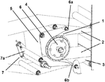
- the present invention focuses on a reversal mechanism 1 of a product placed between a first upper conveyor belt 2 and a second lower conveyor belt 3 .
- the first conveyor belt 2 is linked to at least one cylinder 4 on one end, characterized in that the reversal mechanism 1 contains at least one means for clamping the product placed against the first conveyor belt 2 moving on a portion of the periphery of the cylinder 4 .
- the reversal mechanism 1 of the invention makes it possible to stack several conveyor belts 2 , 3 inside a treatment device, particularly wire heat treatment.
- the reversal mechanism 1 makes it possible to transfer a product between the first upper belt 2 and the second lower belt 3 while retaining the layout and arrangement similar to that of the conveyor belt 2 to the other 3 .
- This transfer quality is obtained through the product's clamping means, which presses the product against the upper conveyor belt 2 while moving on the cylinder 4 .
- This pressure of the product against the conveyor belt 2 turning against the cylinder 4 makes it possible to control the movement of the product while it turns, thereby avoiding the product from chaotically falling while being transferred from one upper conveyor belt 2 to the lower conveyor belt 2 .
- the clamping mechanism is thus arranged to keep the product in place against the upper conveyor belt 2 throughout most of the product's turning operation.
- the clamping means comprises at least one circular band 5 guided around several guide rollers 6 .
- the presence of these different guide rollers 6 makes it possible to manage the trajectory of the circular band 5 so that this circular band 5 can move fluidly without being eroded by friction or harmful interference.
- the circular band 5 can be moved while clamped between two guide rollers moving in counter-rotation.
- the flexible circular band 5 makes it possible to avoid holding the product, by touching and placing pressure only on the thickest part of the product in contact with the conveyor belt 2 on the cylinder 4 .
- the circular band 5 of the clamping means is done in a material that is sufficiently flexible in its length to follow the curves of the guiding rollers 6 and the cylinder 4 .
- the circular band 5 is also flexible in its width to adapt to the variations in thickness of the wire bundle spread out and moving on the upper conveyor belt 2 rotating on the cylinder 4 .
- the circular band 5 has sufficient elasticity in its width to adapt to the variations in thickness that there might be with a spread-out bundle of wires placed on the band 2 around the rotating cylinder 4 .
- This elasticity is paired with sufficient heat resistance to allow it to function in an environment that will undergo heat treatment of the moving wire bundle.
- the circular band 5 can be done in the form of a flexible elastic plastic band, a film, a membrane or also in the form of a knitted fabric or a net or even several bands laid out parallel to one another.
- the circular band 5 moves in the opposite direction as the upper conveyor belt 2 .
- the movement speed of the circular band 5 against the upper conveyor belt 2 is identical to that of the upper conveyor belt 2 .
- the movement of these two bands 2 , 5 can be operated by independent driver mechanisms or by one shared driver mechanism.
- the driver of the circular band 5 is operated by the friction of the upper conveyor belt 2 against that which the circular band 5 is held in pressurized contact.
- the reversal mechanism 1 is characterized in that, since the circular band 5 is pressed against a portion of the cylinder's 4 periphery located on half of cylinder 4 defined in relation to a vertical reference plane passing through the cylinder's 4 rotational axis, the circular band 5 is arranged to pass around at least two guiding rollers 6 a , 6 b arranged in the part of the space opposite the portion of the cylinder 4 in contact with the circular band 5 with regard to the vertical reference plane passing through the rotational axis of the cylinder 4 .
- the first guiding roller 6 a is sufficiently far away from the upper conveyor belt 2 to create a space between the circular band 5 and the upper conveyor belt 2 and to facilitate the insertion of the product being moved on the upper conveyor belt 2 .
- the product is gradually clamped by the circular band 5 while being rotated around the cylinder 4 by the upper conveyor belt 2 , over the upper conveyor belt 2 .
- the second guiding roller 6 b is sufficiently far away from the upper conveyor belt 2 to create a space between the circular band 5 and the upper conveyor belt 2 , below the upper conveyor belt 2 . This arrangement is done so that the product can be secluded and retrieved on the circular band 5 before being placed on the lower conveyor belt 3 .
- the circular band 5 linked to a stressed holding mechanism 7 on at least one point against the first conveyor belt 2 circulating around a portion of the cylinder periphery 4 .
- the stressed holding mechanism 7 acts on the circular band 5 to, on one hand, create stress so that a part of the circular band 5 places pressure against the first conveyor belt 2 and, on the other hand, create a loosening of the circular band 5 so that it moves with at least an optimized fluidity with regard to the limits of stress supported.
- the stressed holding mechanism 7 includes at least one roll 7 a , mounted so that it can move on an axis included in a plane perpendicular to the rotational axis of cylinder 4 .
- the movement of roller 7 a along this particular axis allows the roller 7 a to move closer or farther away to or from the guiding rollers, so that the movement circuit of the circular band 5 is stretched/lengthened or, on the contrary, tightened.
- roller 7 a is linked to one movement axis formed by at least one rail.
- roller 7 a and the rail are linked at one of the ends of the roller 7 a .
- each end of roll 7 a is mounted sliding along a respective rail, the rails positioned on each of the ends of the roller 7 a being arranged along the parallel axis between them.
- At least one portion of the circular band 5 positioned around a guiding roller 6 b is positioned below the first upper conveyor belt 2 and above the second lower conveyor belt 3 .
- This positioning of the circular band 5 allows the circular band 5 , being on one hand positioned under the first upper conveyor belt 2 , to turn the product over and form a transporting structure that carries the reversed product and, on the other hand being positioned over the second lower conveyor belt 3 , to place the turned over product on the second lower conveyor belt 3 .
- the turned-over product between the circular band 5 and the second lower conveyor belt 3 is transferred using simple gravity, when the product moved by the circular band 5 passes the point of reversal of the circular band 5 around the guiding roller 6 b . When it reaches this reversal point, the circular band 5 pivots around the guiding roller 6 b . Since the product held by the circular band 5 is not held on the band, it falls onto the second lower conveyor belt 3 .
- the guiding roller 6 b positioned between the first upper conveyor belt 2 and the second lower conveyor belt 3 is placed as close as possible to the second lower conveyor belt 5 positioned under the guiding roller 6 b , or brought closer to the second lower conveyor belt 3 without touching this band 3 .
- This arrangement can limit the product's falling height when placed on the second lower conveyor belt 3 from the circular band 5 .
- the clamping means may include at least one rigid structure that pivots around an axis parallel to the rotational axis of cylinder 4 and including at least one portion pressed against a part of the first upper conveyor belt 2 on the peripheral surface of the cylinder 4 .
- the rigid structure of the clamping means creates a pressure by one of its sides against the surface of the first upper conveyor belt 2 .
- the portion pressed against the peripheral surface of the cylinder 4 presents a substantially curved shape.
- the curving of this portion is adapted to best follow the curve of the first upper conveyor belt 2 by moving on the cylinder 4 .
- This cooperation of shape thus allows the clamping means to press the product against the first upper conveyor belt 2 along a larger portion of the cylinder's 4 periphery and thus ensure the product is held while being turned over for a longer part of the route.
- the rigid pivoting structure of the clamping means works with a return mechanism, for example a spring, to keep the clamping means pressed against the product being turned over with the first upper conveyor belt 2 .
- this return mechanism can use gravity alone to keep the clamping means against the product and the first upper conveyor belt 2 .
- the lower edge of the rigid structure of the clamping means is arranged to be positioned nearby the second lower conveyor belt 3 . This arrangement thus helps place the product on the second lower conveyor belt 3 from the lower edge of the rigid structure of the clamping means by restricting the falling height when placing the product.
- this includes a surface firmly held by at least one part against the first upper conveyor belt 2 circulating on a portion of the cylinder's 4 periphery. This surface is spread between a high position located above the first upper conveyor belt 2 and a low position located below the first lower conveyor belt 3 . This surface is flexible, which allows it, on one hand, to follow the curve of the first upper conveyor belt 2 where it is moved around cylinder 4 and, on the other hand, to adapt to the varying thickness of the wire bundle spread out and moving the upper conveyor belt 2 and rotating around the cylinder 4 .
- the flexible surface can be in the form of a knitted fabric or a net or even several bands laid out in parallel to one another.
- the surface is held under stress by at least one elastic means, which creates a connection between the fabric and a frame.
- the surface is rectangular and is held under stress by an elastic means positioned at each of its corners. At least one central part of the surface is thus positioned in a way that overlaps the upper conveyor belt 2 where it is being moved around the cylinder 4 . This overlapping is done so that there is a space between the upper edge of the surface and the upper conveyor belt 2 , above the upper conveyor belt 2 , so that it facilitates the insert of the product moved on the upper conveyor belt 2 .
- the overlapping by the surface is done in a way that creates a space with the upper conveyor belt 2 , below the upper conveyor belt 2 . This arrangement is done so that the product can be secluded and retrieved on the surface before being taken and placed by gravity on the second lower conveyor belt 3 .
- the invention also covers a wire heat treatment device, characterized in that the device comprises a structure forming a drying oven, including a first opening for the wire entry and a second opening for the wire exit, integrating at least two superimposed conveyor belts and at least one reversal mechanism, according to the invention.
- the heat treatment device of the invention allows several conveyor belts 2 , 3 moving in opposite directions to be superimposed. This overlapping of the conveyor belts 2 , 3 makes it possible to reduce the floor space occupied by the heat treatment device, even reduce the total volume of the drying oven and thus the amount of energy required for a heat treatment.
- this includes:
- the heat treatment could also relate to a more specific treatment device, for example a steam-type treatment.
- Such a construction with an odd number of conveyor belts makes it possible to position an input and an output for the device on the different sides of the device.
Landscapes
- Engineering & Computer Science (AREA)
- Textile Engineering (AREA)
- Chemical & Material Sciences (AREA)
- Materials Engineering (AREA)
- Mechanical Engineering (AREA)
- Treatment Of Fiber Materials (AREA)
- Structure Of Belt Conveyors (AREA)
Abstract
Description
-
- Three superimposed conveyor belts arranged to define a first upper conveyor belt, a second middle conveyor belt and third lower conveyor belt,
- Two reversal mechanisms arranged so that the first mechanism is positioned to reverse the product from the upper belt to the middle belt and that the second mechanism is positioned to reverse the product from the middle conveyor belt to the lower conveyor belt,
Since the upper conveyor belt is positioned from the entry opening toward the first reversal mechanism and the lower conveyor belt is positioned from the second reversal mechanism toward the device's output.
Claims (19)
Applications Claiming Priority (3)
| Application Number | Priority Date | Filing Date | Title |
|---|---|---|---|
| EP17306328.0A EP3467179B1 (en) | 2017-10-04 | 2017-10-04 | Reversal mechanism |
| EP17306328 | 2017-10-04 | ||
| EP17306328.0 | 2017-10-04 |
Publications (2)
| Publication Number | Publication Date |
|---|---|
| US20190100386A1 US20190100386A1 (en) | 2019-04-04 |
| US10654663B2 true US10654663B2 (en) | 2020-05-19 |
Family
ID=60138320
Family Applications (1)
| Application Number | Title | Priority Date | Filing Date |
|---|---|---|---|
| US16/151,658 Active US10654663B2 (en) | 2017-10-04 | 2018-10-04 | Reversal mechanism |
Country Status (2)
| Country | Link |
|---|---|
| US (1) | US10654663B2 (en) |
| EP (1) | EP3467179B1 (en) |
Cited By (1)
| Publication number | Priority date | Publication date | Assignee | Title |
|---|---|---|---|---|
| US10836581B2 (en) * | 2016-09-21 | 2020-11-17 | Laitram, L.L.C. | Infeed and outfeed assemblies for a conveyor |
Families Citing this family (3)
| Publication number | Priority date | Publication date | Assignee | Title |
|---|---|---|---|---|
| CN110949866A (en) * | 2019-11-14 | 2020-04-03 | 安徽颍上县富颍纺织有限公司 | Bobbin creel for textile processing |
| CN112210862B (en) * | 2020-09-29 | 2021-09-14 | 安徽新虹新材料科技有限公司 | Antibacterial yarn based on natural cotton and production process thereof |
| CN113319929B (en) * | 2021-08-04 | 2021-11-02 | 苏州天立达精密科技股份有限公司 | Film double-side automatic positioning die-cutting laminating device |
Citations (8)
| Publication number | Priority date | Publication date | Assignee | Title |
|---|---|---|---|---|
| US2494731A (en) | 1945-06-26 | 1950-01-17 | Olin Mathieson | Apparatus for steaming textiles |
| GB1047151A (en) | 1963-01-09 | 1966-11-02 | Erba Maschb Ag | Improvements in or relating to yarn conditioning system |
| US3877966A (en) * | 1966-08-22 | 1975-04-15 | Mafit Manufacture De Fils Isol | Process for enamelling wire |
| US4365395A (en) | 1980-03-28 | 1982-12-28 | Hoechst Fibers Industries, Division Of American Hoechst Corporation | Apparatus for handling textile filamentary material |
| US5542547A (en) * | 1992-08-28 | 1996-08-06 | Bell & Howell Phillipsburg Company | Document sorting section having a plurality of primary sorting paths |
| EP1975092A1 (en) | 2007-03-26 | 2008-10-01 | Proditec | Return device for a transfer chain |
| US8443965B2 (en) * | 2010-04-07 | 2013-05-21 | Ykk Corporation | Take-up machine |
| EP3228565A1 (en) | 2016-04-07 | 2017-10-11 | Toyo Jidoki Co., Ltd. | Inversion device |
Family Cites Families (3)
| Publication number | Priority date | Publication date | Assignee | Title |
|---|---|---|---|---|
| FR1072205A (en) | 1952-08-21 | 1954-09-09 | Dryer with several conveyor aprons for retted flax | |
| US6955255B2 (en) | 2003-10-14 | 2005-10-18 | Frito-Lay North America, Inc. | Rotary powered snack piece turnover |
| CN106114966B (en) | 2016-08-19 | 2019-07-16 | 北京泽宇星科技有限公司 | One kind wrapping up in back and lets go covering device |
-
2017
- 2017-10-04 EP EP17306328.0A patent/EP3467179B1/en active Active
-
2018
- 2018-10-04 US US16/151,658 patent/US10654663B2/en active Active
Patent Citations (9)
| Publication number | Priority date | Publication date | Assignee | Title |
|---|---|---|---|---|
| US2494731A (en) | 1945-06-26 | 1950-01-17 | Olin Mathieson | Apparatus for steaming textiles |
| GB1047151A (en) | 1963-01-09 | 1966-11-02 | Erba Maschb Ag | Improvements in or relating to yarn conditioning system |
| US3877966A (en) * | 1966-08-22 | 1975-04-15 | Mafit Manufacture De Fils Isol | Process for enamelling wire |
| US4365395A (en) | 1980-03-28 | 1982-12-28 | Hoechst Fibers Industries, Division Of American Hoechst Corporation | Apparatus for handling textile filamentary material |
| US5542547A (en) * | 1992-08-28 | 1996-08-06 | Bell & Howell Phillipsburg Company | Document sorting section having a plurality of primary sorting paths |
| EP1975092A1 (en) | 2007-03-26 | 2008-10-01 | Proditec | Return device for a transfer chain |
| US20080236994A1 (en) | 2007-03-26 | 2008-10-02 | Proditec | Turnaround device for a transfer line |
| US8443965B2 (en) * | 2010-04-07 | 2013-05-21 | Ykk Corporation | Take-up machine |
| EP3228565A1 (en) | 2016-04-07 | 2017-10-11 | Toyo Jidoki Co., Ltd. | Inversion device |
Non-Patent Citations (1)
| Title |
|---|
| Europe Patent Application No. 17306328.0, Search Report and Written Opinion dated Mar. 16, 2018. |
Cited By (2)
| Publication number | Priority date | Publication date | Assignee | Title |
|---|---|---|---|---|
| US10836581B2 (en) * | 2016-09-21 | 2020-11-17 | Laitram, L.L.C. | Infeed and outfeed assemblies for a conveyor |
| US11332318B2 (en) | 2016-09-21 | 2022-05-17 | Laitram, L.L.C. | Infeed and outfeed assemblies for a conveyor |
Also Published As
| Publication number | Publication date |
|---|---|
| EP3467179A1 (en) | 2019-04-10 |
| US20190100386A1 (en) | 2019-04-04 |
| EP3467179B1 (en) | 2023-02-01 |
Similar Documents
| Publication | Publication Date | Title |
|---|---|---|
| US10654663B2 (en) | Reversal mechanism | |
| US8495799B2 (en) | Fleece layer | |
| CN105794060A (en) | Power line correcting device | |
| KR102259756B1 (en) | A stretching device to stretch a film made of synthetic material at least in the transverse direction | |
| MX2019009471A (en) | Elasticated materials with directional stretch properties. | |
| EP3378792A3 (en) | Guiding device | |
| ATE530311T1 (en) | CONTINUOUS DRILLING MACHINE | |
| US3021663A (en) | Apparatus for false twisting yarn | |
| AU739553B2 (en) | Apparatus for the alignment and depositing of elongate particles such as wood chips, wood fibres or the like on continuously moved support | |
| CA2588205A1 (en) | Apparatus for applying a liquid to a passing web | |
| US20160115628A1 (en) | Cross lapper | |
| RU2015155526A (en) | DECLINING DEVICE FOR A TAPE CONVEYOR CONTAINING AN INFINITE CONVEYOR TAPE | |
| US9725830B2 (en) | Device for conveying a fiber web or a web of nonwoven | |
| CN101367302B (en) | Book binding machine with book block transport system | |
| CZ455099A3 (en) | Scorcher for treating, dyeing, washing or the like treatment of moving band | |
| CN111692865B (en) | Reversing mechanism | |
| CN105369494A (en) | Device for thermal treatment of yarns | |
| CN207567405U (en) | Belt type false twister | |
| ITMI20111590A1 (en) | EQUIPMENT FOR THERMAL TREATMENT OF TUBULAR TEXTILE ARTICLES | |
| JP2013031938A (en) | Drawing machine for sheet material | |
| EP3141650A1 (en) | Edge seeking and guiding device of a fabric | |
| DK1702844T3 (en) | Strapping | |
| JP2009254410A (en) | Calender roll ironer | |
| FR2609057A1 (en) | DEVICE FOR REORIENTING CURRENTS OF FIBERS AND TEXTILE THREADS | |
| CN109650138A (en) | The wrinkle of sheeting removes device and has its cloth spreading machine |
Legal Events
| Date | Code | Title | Description |
|---|---|---|---|
| FEPP | Fee payment procedure |
Free format text: ENTITY STATUS SET TO UNDISCOUNTED (ORIGINAL EVENT CODE: BIG.); ENTITY STATUS OF PATENT OWNER: SMALL ENTITY |
|
| FEPP | Fee payment procedure |
Free format text: ENTITY STATUS SET TO SMALL (ORIGINAL EVENT CODE: SMAL); ENTITY STATUS OF PATENT OWNER: SMALL ENTITY |
|
| AS | Assignment |
Owner name: SUPERBA S.A.S., FRANCE Free format text: ASSIGNMENT OF ASSIGNORS INTEREST;ASSIGNORS:LIEBMANN, HUBERT;MASSOTTE, PHILIPPE;REEL/FRAME:047687/0461 Effective date: 20181010 |
|
| STPP | Information on status: patent application and granting procedure in general |
Free format text: DOCKETED NEW CASE - READY FOR EXAMINATION |
|
| STPP | Information on status: patent application and granting procedure in general |
Free format text: NON FINAL ACTION MAILED |
|
| STPP | Information on status: patent application and granting procedure in general |
Free format text: RESPONSE TO NON-FINAL OFFICE ACTION ENTERED AND FORWARDED TO EXAMINER |
|
| STPP | Information on status: patent application and granting procedure in general |
Free format text: FINAL REJECTION MAILED |
|
| STPP | Information on status: patent application and granting procedure in general |
Free format text: NOTICE OF ALLOWANCE MAILED -- APPLICATION RECEIVED IN OFFICE OF PUBLICATIONS |
|
| STPP | Information on status: patent application and granting procedure in general |
Free format text: PUBLICATIONS -- ISSUE FEE PAYMENT VERIFIED |
|
| STCF | Information on status: patent grant |
Free format text: PATENTED CASE |
|
| MAFP | Maintenance fee payment |
Free format text: PAYMENT OF MAINTENANCE FEE, 4TH YR, SMALL ENTITY (ORIGINAL EVENT CODE: M2551); ENTITY STATUS OF PATENT OWNER: SMALL ENTITY Year of fee payment: 4 |