US10651160B2 - Low profile integrated package - Google Patents
Low profile integrated package Download PDFInfo
- Publication number
- US10651160B2 US10651160B2 US15/867,518 US201815867518A US10651160B2 US 10651160 B2 US10651160 B2 US 10651160B2 US 201815867518 A US201815867518 A US 201815867518A US 10651160 B2 US10651160 B2 US 10651160B2
- Authority
- US
- United States
- Prior art keywords
- redistribution
- package
- die
- interconnect
- interposer
- Prior art date
- Legal status (The legal status is an assumption and is not a legal conclusion. Google has not performed a legal analysis and makes no representation as to the accuracy of the status listed.)
- Active
Links
Images


Classifications
-
- H—ELECTRICITY
- H01—ELECTRIC ELEMENTS
- H01L—SEMICONDUCTOR DEVICES NOT COVERED BY CLASS H10
- H01L25/00—Assemblies consisting of a plurality of individual semiconductor or other solid state devices ; Multistep manufacturing processes thereof
- H01L25/03—Assemblies consisting of a plurality of individual semiconductor or other solid state devices ; Multistep manufacturing processes thereof all the devices being of a type provided for in the same subgroup of groups H01L27/00 - H01L33/00, or in a single subclass of H10K, H10N, e.g. assemblies of rectifier diodes
- H01L25/10—Assemblies consisting of a plurality of individual semiconductor or other solid state devices ; Multistep manufacturing processes thereof all the devices being of a type provided for in the same subgroup of groups H01L27/00 - H01L33/00, or in a single subclass of H10K, H10N, e.g. assemblies of rectifier diodes the devices having separate containers
-
- H—ELECTRICITY
- H01—ELECTRIC ELEMENTS
- H01L—SEMICONDUCTOR DEVICES NOT COVERED BY CLASS H10
- H01L21/00—Processes or apparatus adapted for the manufacture or treatment of semiconductor or solid state devices or of parts thereof
- H01L21/02—Manufacture or treatment of semiconductor devices or of parts thereof
- H01L21/04—Manufacture or treatment of semiconductor devices or of parts thereof the devices having at least one potential-jump barrier or surface barrier, e.g. PN junction, depletion layer or carrier concentration layer
- H01L21/48—Manufacture or treatment of parts, e.g. containers, prior to assembly of the devices, using processes not provided for in a single one of the subgroups H01L21/06 - H01L21/326
- H01L21/4803—Insulating or insulated parts, e.g. mountings, containers, diamond heatsinks
-
- H—ELECTRICITY
- H01—ELECTRIC ELEMENTS
- H01L—SEMICONDUCTOR DEVICES NOT COVERED BY CLASS H10
- H01L21/00—Processes or apparatus adapted for the manufacture or treatment of semiconductor or solid state devices or of parts thereof
- H01L21/02—Manufacture or treatment of semiconductor devices or of parts thereof
- H01L21/04—Manufacture or treatment of semiconductor devices or of parts thereof the devices having at least one potential-jump barrier or surface barrier, e.g. PN junction, depletion layer or carrier concentration layer
- H01L21/48—Manufacture or treatment of parts, e.g. containers, prior to assembly of the devices, using processes not provided for in a single one of the subgroups H01L21/06 - H01L21/326
- H01L21/4814—Conductive parts
- H01L21/4846—Leads on or in insulating or insulated substrates, e.g. metallisation
- H01L21/4853—Connection or disconnection of other leads to or from a metallisation, e.g. pins, wires, bumps
-
- H—ELECTRICITY
- H01—ELECTRIC ELEMENTS
- H01L—SEMICONDUCTOR DEVICES NOT COVERED BY CLASS H10
- H01L21/00—Processes or apparatus adapted for the manufacture or treatment of semiconductor or solid state devices or of parts thereof
- H01L21/02—Manufacture or treatment of semiconductor devices or of parts thereof
- H01L21/04—Manufacture or treatment of semiconductor devices or of parts thereof the devices having at least one potential-jump barrier or surface barrier, e.g. PN junction, depletion layer or carrier concentration layer
- H01L21/48—Manufacture or treatment of parts, e.g. containers, prior to assembly of the devices, using processes not provided for in a single one of the subgroups H01L21/06 - H01L21/326
- H01L21/4814—Conductive parts
- H01L21/4846—Leads on or in insulating or insulated substrates, e.g. metallisation
- H01L21/4857—Multilayer substrates
-
- H—ELECTRICITY
- H01—ELECTRIC ELEMENTS
- H01L—SEMICONDUCTOR DEVICES NOT COVERED BY CLASS H10
- H01L21/00—Processes or apparatus adapted for the manufacture or treatment of semiconductor or solid state devices or of parts thereof
- H01L21/02—Manufacture or treatment of semiconductor devices or of parts thereof
- H01L21/04—Manufacture or treatment of semiconductor devices or of parts thereof the devices having at least one potential-jump barrier or surface barrier, e.g. PN junction, depletion layer or carrier concentration layer
- H01L21/48—Manufacture or treatment of parts, e.g. containers, prior to assembly of the devices, using processes not provided for in a single one of the subgroups H01L21/06 - H01L21/326
- H01L21/4814—Conductive parts
- H01L21/4846—Leads on or in insulating or insulated substrates, e.g. metallisation
- H01L21/486—Via connections through the substrate with or without pins
-
- H—ELECTRICITY
- H01—ELECTRIC ELEMENTS
- H01L—SEMICONDUCTOR DEVICES NOT COVERED BY CLASS H10
- H01L23/00—Details of semiconductor or other solid state devices
- H01L23/48—Arrangements for conducting electric current to or from the solid state body in operation, e.g. leads, terminal arrangements ; Selection of materials therefor
- H01L23/488—Arrangements for conducting electric current to or from the solid state body in operation, e.g. leads, terminal arrangements ; Selection of materials therefor consisting of soldered or bonded constructions
- H01L23/498—Leads, i.e. metallisations or lead-frames on insulating substrates, e.g. chip carriers
- H01L23/49811—Additional leads joined to the metallisation on the insulating substrate, e.g. pins, bumps, wires, flat leads
- H01L23/49816—Spherical bumps on the substrate for external connection, e.g. ball grid arrays [BGA]
-
- H—ELECTRICITY
- H01—ELECTRIC ELEMENTS
- H01L—SEMICONDUCTOR DEVICES NOT COVERED BY CLASS H10
- H01L23/00—Details of semiconductor or other solid state devices
- H01L23/48—Arrangements for conducting electric current to or from the solid state body in operation, e.g. leads, terminal arrangements ; Selection of materials therefor
- H01L23/488—Arrangements for conducting electric current to or from the solid state body in operation, e.g. leads, terminal arrangements ; Selection of materials therefor consisting of soldered or bonded constructions
- H01L23/498—Leads, i.e. metallisations or lead-frames on insulating substrates, e.g. chip carriers
- H01L23/49822—Multilayer substrates
-
- H—ELECTRICITY
- H01—ELECTRIC ELEMENTS
- H01L—SEMICONDUCTOR DEVICES NOT COVERED BY CLASS H10
- H01L23/00—Details of semiconductor or other solid state devices
- H01L23/52—Arrangements for conducting electric current within the device in operation from one component to another, i.e. interconnections, e.g. wires, lead frames
- H01L23/538—Arrangements for conducting electric current within the device in operation from one component to another, i.e. interconnections, e.g. wires, lead frames the interconnection structure between a plurality of semiconductor chips being formed on, or in, insulating substrates
- H01L23/5383—Multilayer substrates
-
- H—ELECTRICITY
- H01—ELECTRIC ELEMENTS
- H01L—SEMICONDUCTOR DEVICES NOT COVERED BY CLASS H10
- H01L23/00—Details of semiconductor or other solid state devices
- H01L23/52—Arrangements for conducting electric current within the device in operation from one component to another, i.e. interconnections, e.g. wires, lead frames
- H01L23/538—Arrangements for conducting electric current within the device in operation from one component to another, i.e. interconnections, e.g. wires, lead frames the interconnection structure between a plurality of semiconductor chips being formed on, or in, insulating substrates
- H01L23/5384—Conductive vias through the substrate with or without pins, e.g. buried coaxial conductors
-
- H—ELECTRICITY
- H01—ELECTRIC ELEMENTS
- H01L—SEMICONDUCTOR DEVICES NOT COVERED BY CLASS H10
- H01L23/00—Details of semiconductor or other solid state devices
- H01L23/52—Arrangements for conducting electric current within the device in operation from one component to another, i.e. interconnections, e.g. wires, lead frames
- H01L23/538—Arrangements for conducting electric current within the device in operation from one component to another, i.e. interconnections, e.g. wires, lead frames the interconnection structure between a plurality of semiconductor chips being formed on, or in, insulating substrates
- H01L23/5389—Arrangements for conducting electric current within the device in operation from one component to another, i.e. interconnections, e.g. wires, lead frames the interconnection structure between a plurality of semiconductor chips being formed on, or in, insulating substrates the chips being integrally enclosed by the interconnect and support structures
-
- H—ELECTRICITY
- H01—ELECTRIC ELEMENTS
- H01L—SEMICONDUCTOR DEVICES NOT COVERED BY CLASS H10
- H01L24/00—Arrangements for connecting or disconnecting semiconductor or solid-state bodies; Methods or apparatus related thereto
- H01L24/01—Means for bonding being attached to, or being formed on, the surface to be connected, e.g. chip-to-package, die-attach, "first-level" interconnects; Manufacturing methods related thereto
- H01L24/10—Bump connectors ; Manufacturing methods related thereto
- H01L24/15—Structure, shape, material or disposition of the bump connectors after the connecting process
- H01L24/16—Structure, shape, material or disposition of the bump connectors after the connecting process of an individual bump connector
-
- H—ELECTRICITY
- H01—ELECTRIC ELEMENTS
- H01L—SEMICONDUCTOR DEVICES NOT COVERED BY CLASS H10
- H01L2224/00—Indexing scheme for arrangements for connecting or disconnecting semiconductor or solid-state bodies and methods related thereto as covered by H01L24/00
- H01L2224/01—Means for bonding being attached to, or being formed on, the surface to be connected, e.g. chip-to-package, die-attach, "first-level" interconnects; Manufacturing methods related thereto
- H01L2224/10—Bump connectors; Manufacturing methods related thereto
- H01L2224/15—Structure, shape, material or disposition of the bump connectors after the connecting process
- H01L2224/16—Structure, shape, material or disposition of the bump connectors after the connecting process of an individual bump connector
- H01L2224/161—Disposition
- H01L2224/16151—Disposition the bump connector connecting between a semiconductor or solid-state body and an item not being a semiconductor or solid-state body, e.g. chip-to-substrate, chip-to-passive
- H01L2224/16221—Disposition the bump connector connecting between a semiconductor or solid-state body and an item not being a semiconductor or solid-state body, e.g. chip-to-substrate, chip-to-passive the body and the item being stacked
- H01L2224/16225—Disposition the bump connector connecting between a semiconductor or solid-state body and an item not being a semiconductor or solid-state body, e.g. chip-to-substrate, chip-to-passive the body and the item being stacked the item being non-metallic, e.g. insulating substrate with or without metallisation
- H01L2224/16227—Disposition the bump connector connecting between a semiconductor or solid-state body and an item not being a semiconductor or solid-state body, e.g. chip-to-substrate, chip-to-passive the body and the item being stacked the item being non-metallic, e.g. insulating substrate with or without metallisation the bump connector connecting to a bond pad of the item
-
- H—ELECTRICITY
- H01—ELECTRIC ELEMENTS
- H01L—SEMICONDUCTOR DEVICES NOT COVERED BY CLASS H10
- H01L2224/00—Indexing scheme for arrangements for connecting or disconnecting semiconductor or solid-state bodies and methods related thereto as covered by H01L24/00
- H01L2224/01—Means for bonding being attached to, or being formed on, the surface to be connected, e.g. chip-to-package, die-attach, "first-level" interconnects; Manufacturing methods related thereto
- H01L2224/10—Bump connectors; Manufacturing methods related thereto
- H01L2224/15—Structure, shape, material or disposition of the bump connectors after the connecting process
- H01L2224/16—Structure, shape, material or disposition of the bump connectors after the connecting process of an individual bump connector
- H01L2224/161—Disposition
- H01L2224/16151—Disposition the bump connector connecting between a semiconductor or solid-state body and an item not being a semiconductor or solid-state body, e.g. chip-to-substrate, chip-to-passive
- H01L2224/16221—Disposition the bump connector connecting between a semiconductor or solid-state body and an item not being a semiconductor or solid-state body, e.g. chip-to-substrate, chip-to-passive the body and the item being stacked
- H01L2224/16225—Disposition the bump connector connecting between a semiconductor or solid-state body and an item not being a semiconductor or solid-state body, e.g. chip-to-substrate, chip-to-passive the body and the item being stacked the item being non-metallic, e.g. insulating substrate with or without metallisation
- H01L2224/16237—Disposition the bump connector connecting between a semiconductor or solid-state body and an item not being a semiconductor or solid-state body, e.g. chip-to-substrate, chip-to-passive the body and the item being stacked the item being non-metallic, e.g. insulating substrate with or without metallisation the bump connector connecting to a bonding area disposed in a recess of the surface of the item
-
- H—ELECTRICITY
- H01—ELECTRIC ELEMENTS
- H01L—SEMICONDUCTOR DEVICES NOT COVERED BY CLASS H10
- H01L2224/00—Indexing scheme for arrangements for connecting or disconnecting semiconductor or solid-state bodies and methods related thereto as covered by H01L24/00
- H01L2224/01—Means for bonding being attached to, or being formed on, the surface to be connected, e.g. chip-to-package, die-attach, "first-level" interconnects; Manufacturing methods related thereto
- H01L2224/26—Layer connectors, e.g. plate connectors, solder or adhesive layers; Manufacturing methods related thereto
- H01L2224/31—Structure, shape, material or disposition of the layer connectors after the connecting process
- H01L2224/32—Structure, shape, material or disposition of the layer connectors after the connecting process of an individual layer connector
- H01L2224/321—Disposition
- H01L2224/32151—Disposition the layer connector connecting between a semiconductor or solid-state body and an item not being a semiconductor or solid-state body, e.g. chip-to-substrate, chip-to-passive
- H01L2224/32221—Disposition the layer connector connecting between a semiconductor or solid-state body and an item not being a semiconductor or solid-state body, e.g. chip-to-substrate, chip-to-passive the body and the item being stacked
- H01L2224/32225—Disposition the layer connector connecting between a semiconductor or solid-state body and an item not being a semiconductor or solid-state body, e.g. chip-to-substrate, chip-to-passive the body and the item being stacked the item being non-metallic, e.g. insulating substrate with or without metallisation
-
- H—ELECTRICITY
- H01—ELECTRIC ELEMENTS
- H01L—SEMICONDUCTOR DEVICES NOT COVERED BY CLASS H10
- H01L2224/00—Indexing scheme for arrangements for connecting or disconnecting semiconductor or solid-state bodies and methods related thereto as covered by H01L24/00
- H01L2224/73—Means for bonding being of different types provided for in two or more of groups H01L2224/10, H01L2224/18, H01L2224/26, H01L2224/34, H01L2224/42, H01L2224/50, H01L2224/63, H01L2224/71
- H01L2224/732—Location after the connecting process
- H01L2224/73201—Location after the connecting process on the same surface
- H01L2224/73203—Bump and layer connectors
- H01L2224/73204—Bump and layer connectors the bump connector being embedded into the layer connector
-
- H—ELECTRICITY
- H01—ELECTRIC ELEMENTS
- H01L—SEMICONDUCTOR DEVICES NOT COVERED BY CLASS H10
- H01L2225/00—Details relating to assemblies covered by the group H01L25/00 but not provided for in its subgroups
- H01L2225/03—All the devices being of a type provided for in the same subgroup of groups H01L27/00 - H01L33/648 and H10K99/00
- H01L2225/10—All the devices being of a type provided for in the same subgroup of groups H01L27/00 - H01L33/648 and H10K99/00 the devices having separate containers
- H01L2225/1005—All the devices being of a type provided for in the same subgroup of groups H01L27/00 - H01L33/648 and H10K99/00 the devices having separate containers the devices being of a type provided for in group H01L27/00
- H01L2225/1011—All the devices being of a type provided for in the same subgroup of groups H01L27/00 - H01L33/648 and H10K99/00 the devices having separate containers the devices being of a type provided for in group H01L27/00 the containers being in a stacked arrangement
- H01L2225/1017—All the devices being of a type provided for in the same subgroup of groups H01L27/00 - H01L33/648 and H10K99/00 the devices having separate containers the devices being of a type provided for in group H01L27/00 the containers being in a stacked arrangement the lowermost container comprising a device support
- H01L2225/1023—All the devices being of a type provided for in the same subgroup of groups H01L27/00 - H01L33/648 and H10K99/00 the devices having separate containers the devices being of a type provided for in group H01L27/00 the containers being in a stacked arrangement the lowermost container comprising a device support the support being an insulating substrate
-
- H—ELECTRICITY
- H01—ELECTRIC ELEMENTS
- H01L—SEMICONDUCTOR DEVICES NOT COVERED BY CLASS H10
- H01L2225/00—Details relating to assemblies covered by the group H01L25/00 but not provided for in its subgroups
- H01L2225/03—All the devices being of a type provided for in the same subgroup of groups H01L27/00 - H01L33/648 and H10K99/00
- H01L2225/10—All the devices being of a type provided for in the same subgroup of groups H01L27/00 - H01L33/648 and H10K99/00 the devices having separate containers
- H01L2225/1005—All the devices being of a type provided for in the same subgroup of groups H01L27/00 - H01L33/648 and H10K99/00 the devices having separate containers the devices being of a type provided for in group H01L27/00
- H01L2225/1011—All the devices being of a type provided for in the same subgroup of groups H01L27/00 - H01L33/648 and H10K99/00 the devices having separate containers the devices being of a type provided for in group H01L27/00 the containers being in a stacked arrangement
- H01L2225/1017—All the devices being of a type provided for in the same subgroup of groups H01L27/00 - H01L33/648 and H10K99/00 the devices having separate containers the devices being of a type provided for in group H01L27/00 the containers being in a stacked arrangement the lowermost container comprising a device support
- H01L2225/1035—All the devices being of a type provided for in the same subgroup of groups H01L27/00 - H01L33/648 and H10K99/00 the devices having separate containers the devices being of a type provided for in group H01L27/00 the containers being in a stacked arrangement the lowermost container comprising a device support the device being entirely enclosed by the support, e.g. high-density interconnect [HDI]
-
- H—ELECTRICITY
- H01—ELECTRIC ELEMENTS
- H01L—SEMICONDUCTOR DEVICES NOT COVERED BY CLASS H10
- H01L2225/00—Details relating to assemblies covered by the group H01L25/00 but not provided for in its subgroups
- H01L2225/03—All the devices being of a type provided for in the same subgroup of groups H01L27/00 - H01L33/648 and H10K99/00
- H01L2225/10—All the devices being of a type provided for in the same subgroup of groups H01L27/00 - H01L33/648 and H10K99/00 the devices having separate containers
- H01L2225/1005—All the devices being of a type provided for in the same subgroup of groups H01L27/00 - H01L33/648 and H10K99/00 the devices having separate containers the devices being of a type provided for in group H01L27/00
- H01L2225/1011—All the devices being of a type provided for in the same subgroup of groups H01L27/00 - H01L33/648 and H10K99/00 the devices having separate containers the devices being of a type provided for in group H01L27/00 the containers being in a stacked arrangement
- H01L2225/1041—Special adaptations for top connections of the lowermost container, e.g. redistribution layer, integral interposer
-
- H—ELECTRICITY
- H01—ELECTRIC ELEMENTS
- H01L—SEMICONDUCTOR DEVICES NOT COVERED BY CLASS H10
- H01L2225/00—Details relating to assemblies covered by the group H01L25/00 but not provided for in its subgroups
- H01L2225/03—All the devices being of a type provided for in the same subgroup of groups H01L27/00 - H01L33/648 and H10K99/00
- H01L2225/10—All the devices being of a type provided for in the same subgroup of groups H01L27/00 - H01L33/648 and H10K99/00 the devices having separate containers
- H01L2225/1005—All the devices being of a type provided for in the same subgroup of groups H01L27/00 - H01L33/648 and H10K99/00 the devices having separate containers the devices being of a type provided for in group H01L27/00
- H01L2225/1011—All the devices being of a type provided for in the same subgroup of groups H01L27/00 - H01L33/648 and H10K99/00 the devices having separate containers the devices being of a type provided for in group H01L27/00 the containers being in a stacked arrangement
- H01L2225/1047—Details of electrical connections between containers
- H01L2225/1058—Bump or bump-like electrical connections, e.g. balls, pillars, posts
-
- H—ELECTRICITY
- H01—ELECTRIC ELEMENTS
- H01L—SEMICONDUCTOR DEVICES NOT COVERED BY CLASS H10
- H01L2225/00—Details relating to assemblies covered by the group H01L25/00 but not provided for in its subgroups
- H01L2225/03—All the devices being of a type provided for in the same subgroup of groups H01L27/00 - H01L33/648 and H10K99/00
- H01L2225/10—All the devices being of a type provided for in the same subgroup of groups H01L27/00 - H01L33/648 and H10K99/00 the devices having separate containers
- H01L2225/1005—All the devices being of a type provided for in the same subgroup of groups H01L27/00 - H01L33/648 and H10K99/00 the devices having separate containers the devices being of a type provided for in group H01L27/00
- H01L2225/1011—All the devices being of a type provided for in the same subgroup of groups H01L27/00 - H01L33/648 and H10K99/00 the devices having separate containers the devices being of a type provided for in group H01L27/00 the containers being in a stacked arrangement
- H01L2225/1076—Shape of the containers
- H01L2225/1088—Arrangements to limit the height of the assembly
-
- H—ELECTRICITY
- H01—ELECTRIC ELEMENTS
- H01L—SEMICONDUCTOR DEVICES NOT COVERED BY CLASS H10
- H01L23/00—Details of semiconductor or other solid state devices
- H01L23/28—Encapsulations, e.g. encapsulating layers, coatings, e.g. for protection
- H01L23/31—Encapsulations, e.g. encapsulating layers, coatings, e.g. for protection characterised by the arrangement or shape
- H01L23/3107—Encapsulations, e.g. encapsulating layers, coatings, e.g. for protection characterised by the arrangement or shape the device being completely enclosed
- H01L23/3121—Encapsulations, e.g. encapsulating layers, coatings, e.g. for protection characterised by the arrangement or shape the device being completely enclosed a substrate forming part of the encapsulation
- H01L23/3128—Encapsulations, e.g. encapsulating layers, coatings, e.g. for protection characterised by the arrangement or shape the device being completely enclosed a substrate forming part of the encapsulation the substrate having spherical bumps for external connection
-
- H—ELECTRICITY
- H01—ELECTRIC ELEMENTS
- H01L—SEMICONDUCTOR DEVICES NOT COVERED BY CLASS H10
- H01L23/00—Details of semiconductor or other solid state devices
- H01L23/48—Arrangements for conducting electric current to or from the solid state body in operation, e.g. leads, terminal arrangements ; Selection of materials therefor
- H01L23/488—Arrangements for conducting electric current to or from the solid state body in operation, e.g. leads, terminal arrangements ; Selection of materials therefor consisting of soldered or bonded constructions
- H01L23/498—Leads, i.e. metallisations or lead-frames on insulating substrates, e.g. chip carriers
- H01L23/49827—Via connections through the substrates, e.g. pins going through the substrate, coaxial cables
-
- H—ELECTRICITY
- H01—ELECTRIC ELEMENTS
- H01L—SEMICONDUCTOR DEVICES NOT COVERED BY CLASS H10
- H01L25/00—Assemblies consisting of a plurality of individual semiconductor or other solid state devices ; Multistep manufacturing processes thereof
- H01L25/03—Assemblies consisting of a plurality of individual semiconductor or other solid state devices ; Multistep manufacturing processes thereof all the devices being of a type provided for in the same subgroup of groups H01L27/00 - H01L33/00, or in a single subclass of H10K, H10N, e.g. assemblies of rectifier diodes
- H01L25/10—Assemblies consisting of a plurality of individual semiconductor or other solid state devices ; Multistep manufacturing processes thereof all the devices being of a type provided for in the same subgroup of groups H01L27/00 - H01L33/00, or in a single subclass of H10K, H10N, e.g. assemblies of rectifier diodes the devices having separate containers
- H01L25/105—Assemblies consisting of a plurality of individual semiconductor or other solid state devices ; Multistep manufacturing processes thereof all the devices being of a type provided for in the same subgroup of groups H01L27/00 - H01L33/00, or in a single subclass of H10K, H10N, e.g. assemblies of rectifier diodes the devices having separate containers the devices being of a type provided for in group H01L27/00
-
- H—ELECTRICITY
- H01—ELECTRIC ELEMENTS
- H01L—SEMICONDUCTOR DEVICES NOT COVERED BY CLASS H10
- H01L2924/00—Indexing scheme for arrangements or methods for connecting or disconnecting semiconductor or solid-state bodies as covered by H01L24/00
- H01L2924/15—Details of package parts other than the semiconductor or other solid state devices to be connected
- H01L2924/151—Die mounting substrate
- H01L2924/1515—Shape
- H01L2924/15153—Shape the die mounting substrate comprising a recess for hosting the device
Definitions
- Various features relate generally to an integrated package, and more specifically to a low profile integrated package.
- FIG. 1 illustrates a package on package (PoP) device 100 that includes a first package 102 and a second package 104 .
- the first package 102 includes a first die 120 , a first package substrate 122 and a first encapsulation layer 129 .
- the first package substrate 122 includes a first plurality of pads 124 and a first pad 126 .
- the first die 120 is coupled to the first package substrate 122 through a first plurality of solder balls 128 .
- the first die 120 is coupled to the first plurality of pads 124 through the first plurality of solder balls 128 .
- the encapsulation layer 129 encapsulates the first die 120 and the first plurality of solder balls 128 .
- a second plurality of solder balls 130 is coupled to the first package substrate 122 .
- the second package 104 includes a second die 140 , a second package substrate 142 , a second pad 146 , a wire bond 148 , and a second encapsulation layer 160 .
- the second die 140 is coupled to the second package substrate 142 .
- the wire bond 148 is coupled to the second die 140 and a pad of the second package substrate 142 .
- the second package substrate 142 is needed in order to provide structural support for the second package 104 , as well as providing a base for the second die 140 , and to provide an electrical path to the first package 102 .
- the second package 104 is coupled to the first package 102 through a third solder ball 156 .
- the third solder ball 156 is coupled to the first pad 126 of the first package substrate 122 , and the second pad 146 of the second package 104 .
- Each package has a height of about 500 microns ( ⁇ m) or greater.
- the combined height (e.g., Z-height) of the package on package (PoP) device 100 is greater 1000 microns ( ⁇ m). That is, the height between the top of the package on package (PoP) device 100 (e.g., top of the second encapsulation layer 160 ) and the bottom of the package on package (PoP) device 100 (e.g., bottom of the second plurality of solder balls 130 ) is greater than 1000 microns ( ⁇ m).
- Various features relate generally to an integrated package, and more specifically to a low profile integrated package.
- One example provides a package that includes a substrate comprising an interposer interconnect and a cavity, a redistribution portion coupled to the substrate, the redistribution comprising a plurality of redistribution interconnects, and a first die coupled to the redistribution portion through the cavity of the substrate.
- a substantial region between a side surface of the first die and the substrate is free of an encapsulation layer.
- Another example provides a package that includes a substrate comprising an interposer interconnect and a cavity, a redistribution portion coupled to the substrate, the redistribution comprising a plurality of redistribution interconnects and a barrier layer, wherein the barrier layer is coupled to the interposer interconnect.
- the package includes a first die coupled to the redistribution portion through the cavity of the substrate.
- Another example provides an apparatus that includes means for substrate comprising an interposer interconnect and a cavity, means for redistribution coupled to the means for substrate, the means for redistribution comprising a plurality of redistribution interconnects, and a first die coupled to the means for redistribution through the cavity of the means for substrate.
- a substantial region between a side surface of the first die and the means for substrate is free of an encapsulation layer.
- Another example provides a package that includes a substrate comprising an interposer interconnect and a cavity, a redistribution portion coupled to the substrate, the redistribution comprising a plurality of redistribution interconnects and a barrier layer, wherein the barrier layer is coupled to the interposer interconnect.
- the package includes a first die coupled to the redistribution portion through the cavity of the substrate.
- FIG. 1 illustrates a cross-sectional view of a package on package (PoP) device.
- PoP package on package
- FIG. 2 illustrates a cross-sectional view of an example of a low profile package that includes a die, an interposer and a redistribution portion.
- FIG. 3 illustrates a close up cross-sectional view of part of a low profile package that includes a die, an interposer and a redistribution portion.
- FIG. 4 (which includes FIGS. 4A-4D ) illustrates an example of a sequence for fabricating an interposer for a low profile package.
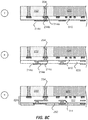
- FIG. 5 (which includes FIGS. 5A-5C ) illustrates another example of a sequence for fabricating an interposer for a low profile package.
- FIG. 6 (which includes FIGS. 6A-6B ) illustrates an example of a sequence for fabricating an interposer for a low profile package.
- FIG. 7 illustrates a flow diagram of an exemplary method for fabricating an interposer for a low profile package.
- FIG. 8 (which includes FIGS. 8A-8E ) illustrates an example of a sequence for fabricating a low profile package that includes a die, an interposer and a redistribution portion.
- FIG. 9 illustrates a flow diagram of an exemplary method for fabricating a low profile package that includes a die, an interposer and a redistribution portion.
- FIG. 10 illustrates various electronic devices that may include the various integrated devices, integrated device packages, semiconductor devices, dies, integrated circuits, and/or packages described herein.
- a device package e.g., an integrated package, an integrated circuit (IC) package
- a substrate comprising an interposer interconnect and a cavity
- a redistribution portion coupled to the substrate, the redistribution comprising a plurality of redistribution interconnects
- a first die coupled to the redistribution portion through the cavity of the substrate.
- a substantial region between a side surface of the first die and the substrate is free of an encapsulation layer.
- a substantial area of a side surface of the first die is free of an encapsulation layer.
- the substrate is free of a metal ring that surrounds the first die.
- the integrated package (e.g., integrated circuit (IC) package) comprises a thickness in a range of about 200-300 microns ( ⁇ m).
- the redistribution portion comprises a barrier layer and a first interconnect coupled to the barrier layer.
- the barrier layer is coupled to the interposer interconnect.
- the integrated package includes a backside redistribution portion.
- the height of the device package may be defined along the Z-direction of the device package, which is shown in the figures of the present disclosure.
- the Z-direction of the device package may be defined along an axis between a top portion and a bottom portion of the device package.
- top and bottom may be arbitrarily assigned, however as an example, the top portion of the device package may be a portion comprising a die or a backside redistribution portion, while a bottom portion of the device package may be a portion comprising a redistribution portion or a plurality of solder balls.
- the top portion of the device package may be a back side of the device package, and the bottom portion of the device package may be a front side of the device package.
- the front side of the device package may be an active side of the device package.
- a top portion may be a higher portion relative to a lower portion.
- a bottom portion may be a lower portion relative to a higher portion. Further examples of top portions and bottom portions will be further described below.
- the X-Y directions of the device package may refer to the lateral direction and/or footprint of the device package. Examples of X-Y directions are shown in the figures of the present disclosure and/or further described below. In many of the figures of the present disclosure, the device packages and their respective components are shown across a X-Z cross-section or X-Z plane. However, in some implementations, the device packages and their representative components may be represented across a Y-Z cross-section or Y-Z plane.
- an interconnect is an element or component of a device or package that allows or facilitates an electrical connection between two points, elements and/or components.
- an interconnect may include a trace, a via, a pad, a pillar, a redistribution metal layer, a barrier layer, and/or an under bump metallization (UBM) layer.
- UBM under bump metallization
- an interconnect is an electrically conductive material that may provide an electrical path for a signal (e.g., data signal, ground signal, power signal).
- An interconnect may be part of a circuit.
- An interconnect may include more than one element or component.
- FIG. 2 illustrates a package 200 that is a low profile package.
- the package 200 may be an integrated package (e.g., an integrated circuit (IC) package).
- the package 200 may be a bottom package of a package on package (PoP) device.
- the package 200 has a height (e.g., Z-height) that is less than other packages.
- the height of the package 200 is in a range of about 200-300 microns ( ⁇ m).
- the height of other known comparable packages may be about 500 microns ( ⁇ m) or greater.
- the term comparable package means a package that has a comparable or similar footprint or surface area and functionality, as another package.
- the package 200 of FIG. 2 provides a package that has a lower height profile than other comparable packages.
- the package 200 includes a first die 210 , a redistribution portion 220 , an interposer 230 , and a backside redistribution portion 240 .
- the first die 210 is coupled to a first surface of the redistribution portion 220 .
- the first die 210 includes a plurality of interconnects 218 that is coupled to the redistribution portion 220 .
- the plurality of interconnects 218 may include pillars and/or solder.
- a first surface of the interposer 230 is coupled to the first surface the redistribution portion 220 .
- the backside redistribution portion 240 is coupled to a second surface of the interposer 230 .
- the interposer 230 includes a cavity 231 .
- the first die 210 is located in the cavity 231 of the interposer 230 such that the interposer 230 laterally surrounds the first die 210 .
- the interposer 230 may be a means for interposer that includes one or more interposer interconnects (e.g., vias).
- the interposer 230 may be a form of a substrate (e.g., means for substrate) that includes one or more interposer interconnects.
- the redistribution portion 220 includes at least one dielectric layer 222 , a plurality of redistribution interconnects 214 and at least one barrier layer 216 (e.g., means for barrier).
- the redistribution portion 220 may also include a solder resist layer 250 .
- the redistribution portion 220 may be a means for redistribution.
- the plurality of redistribution interconnects 214 may includes several redistribution interconnects (e.g., 214 a - 214 f as shown in FIG. 3 ).
- the plurality of redistribution interconnects 214 may comprise a trace, a pad and/or a via.
- the barrier layer 216 (e.g., means for barrier) is similar to a redistribution interconnect, but is made of a different material or composition than the plurality of redistribution interconnects 214 .
- the barrier layer 216 may include nickel (Ni).
- the barrier layer 216 is used to control with greater accuracy and precision what it etched in the package 200 , resulting in better yields and more reliable connections in the package 200 .
- An exemplary use and purpose of the barrier layer 216 is further illustrated and described in detail in FIGS. 8A-8E .
- the plurality of redistribution interconnects 214 may include copper (Cu).
- a solder is coupled to the redistribution portion 220 .
- the redistribution portion 220 will be described in more details below in FIG. 3 .
- the interposer 230 includes at least one dielectric layer 232 and at least one interposer interconnect 234 .
- the interposer interconnect 234 travels through the dielectric layer 232 .
- the interposer interconnect 234 is coupled to the barrier layer 216 of the redistribution portion 220 .
- the interposer interconnect 234 may include a via.
- the interposer interconnect 234 (e.g., vias) in the interposer 230 may have a diameter or width in a range of about 70-100 microns ( ⁇ m).
- the interposer 230 will be described in more details below in FIG. 3 .
- the backside redistribution portion 240 includes a dielectric layer 242 , a redistribution interconnect 244 and a redistribution interconnect 246 .
- the redistribution interconnect 244 may include a via, and the redistribution interconnect 246 may include a trace.
- the backside redistribution portion 240 may also include other redistribution interconnects, such as a pad.
- the redistribution interconnect 244 is coupled to the interposer interconnect 234 .
- the backside redistribution portion 240 may be a means for backside redistribution.
- the package 200 has a much lower profile or thickness than other known packages.
- the package 200 can be fabricated without the use of an encapsulation layer that encapsulates the first die 210 .
- the fabrication process requires that an encapsulation layer be used as support for the die. Without the encapsulation layer, it would not be possible to fabricate such processes. This is because the fabrication of other known packages requires the die to be provided early in the fabrication process. Such fabrication processes produce lower integrated devices yield and thus are inherently costlier.
- FIGS the case of the package 200 , as will be further described below in FIGS.
- an encapsulation layer is optional for the package 200 , which saves time and money, reducing the overall cost the package 200 .
- a substantial portion of the side surface of the first die 210 is free of an encapsulation layer. That is, in some implementations of the package 200 , the side surface of the first die 210 that is facing the interposer 230 (e.g., facing the dielectric layer 232 of the interposer 230 ) is substantially free of an encapsulation layer (e.g., means for encapsulation).
- a region (e.g., lateral region) and/or gap (e.g., lateral gap) between the first die 210 and the interposer 230 (e.g., substrate) is substantially free of an encapsulation layer.
- the term substantially free may mean that at least fifty percent (50%) of the side surface of the first die 210 facing the interposer 230 is free of a material (e.g., encapsulation layer) and/or or at least fifty percent (50%) of a region (e.g., lateral region) and/or gap (e.g., lateral gap) between the side surface of the first die 210 and the interposer 230 is free of a material (e.g., encapsulation layer).
- the package 200 may be a very thin package that is formed by coupling the first die 210 to the package later in a fabrication process.
- the lateral gap is so small that very little encapsulant (e.g., mold, resin, epoxy) would be able to flow through if the encapsulant would be provided after the package 200 is fabricated.
- the overall size or footprint of package may be reduced because there is no need to account for the extra material (e.g., encapsulation layer) when creating the cavity 231 in the interposer 230 .
- some implementations may still include an encapsulation layer (not shown) that is formed over a backside of the first die 210 .
- some implementations of the package 200 may include an encapsulation layer that at least partially encapsulates the first die 210 .
- an encapsulant e.g., encapsulation layer
- examples of an encapsulation layer include a mold, a resin, and/or an epoxy fill.
- the interposer includes a metal ring (e.g., copper ring) that surrounds a die.
- the metal ring is a by-product or artifact of the fabrication process used to fabricate these known packages.
- the metal ring serves no functional purpose in these known packages (e.g., does not provide an electrical path in the known package) and thus takes up unnecessary spaces in these known packages.
- this metal ring in an interposer is not found in the package 200 nor the interposer 230 .
- the package 200 and the interposer 230 are free of a metal ring that surrounds the first die 210 , simplifying the package 200 and the interposer 230 , and allowing other interconnects (e.g., interposer interconnects) to pass through in a space that would have otherwise been used by a metal ring.
- the absence of the metal ring in the interposer 230 and the package 200 is made possible through the fabrication process (e.g., FIGS. 8A-8E ) described in the present application.
- the package 200 is made possible through fabrication processes described in the present application. These fabrication processes are described further below.
- FIG. 3 illustrates a close up profile view of the package 200 .
- the package 200 includes the first die 210 , the redistribution portion 220 , the interposer 230 and the backside redistribution portion 240 .
- the height of the package 200 is in a range of about 200-300 microns ( ⁇ m).
- a side surface of the first die 210 that is facing the interposer 230 is substantially free of an encapsulation layer.
- a region (e.g., lateral region) and/or gap (e.g., lateral gap) between the first die 210 and the interposer 230 (e.g., substrate) is substantially free of an encapsulation layer.
- substantially free may mean that at least fifty percent (50%) of the side surface of the first die 210 facing the interposer 230 (e.g., substrate) is free of a material (e.g., encapsulation layer) and/or or at least fifty percent (50%) of a region (e.g., lateral region) and/or gap (e.g., lateral gap) between the side surface of the first die 210 and the interposer 230 (e.g., substrate) is free of a material (e.g., encapsulation layer). It is noted that in some implementations, there may be an encapsulation layer between the first die 210 and the interposer 230 (e.g., substrate comprising interposer interconnect).
- the first die 210 is located in the cavity 231 of the interposer 230 .
- the first die 210 is laterally surrounded by the interposer 230 .
- An active side of the first die 210 faces the redistribution portion 220 .
- the first die 210 is coupled (e.g., electrically coupled) to the redistribution portion 220 through the plurality of interconnects 218 .
- the plurality of interconnects 218 is directly coupled to the plurality of redistribution interconnects 214 .
- the redistribution portion 220 includes at least one dielectric layer 222 , the plurality of redistribution interconnects 214 , at least one barrier layer 216 and the solder resist layer 250 .
- the plurality of redistribution interconnects 214 includes a redistribution interconnect 214 a , a redistribution interconnect 214 b , a redistribution interconnect 214 c , a redistribution interconnect 214 d , a redistribution interconnect 214 e , and a redistribution interconnect 214 f.
- the redistribution interconnect 214 a (e.g., pad) is coupled to the barrier layer 216 .
- the redistribution interconnect 214 b (e.g., via) is coupled to the redistribution interconnect 214 a .
- the redistribution interconnect 214 c (e.g., trace) is coupled to the redistribution interconnect 214 b .
- the redistribution interconnect 214 d (e.g., via) is coupled to the redistribution interconnect 214 c .
- the redistribution interconnect 214 e (e.g., pad) is coupled to the redistribution interconnect 214 d .
- the redistribution interconnect 214 f (e.g., pad) is coupled to an interconnect from the plurality of interconnects 218 of the first die 210 .
- the plurality of interconnects 218 may be at least partially embedded in the redistribution portion 220 .
- the plurality of interconnects 218 may be at least partially embedded in the dielectric layer 222 of the redistribution portion 220 .
- the redistribution interconnects 214 a and 214 f are on a first metal layer (M 1 ) of the redistribution portion 220
- the redistribution interconnect 214 b is between the first and a second metal layers (M 1 -M 2 ) of the redistribution portion 220
- the redistribution interconnect 214 c is on a second metal layer (M 2 ) of the redistribution portion 220
- the redistribution interconnect 214 d is between a second and third metal layers (M 2 -M 3 ) of the redistribution portion 220
- the redistribution interconnect 214 e is on a third metal layer (M 3 ) of the redistribution portion 220 .
- the first metal layer (M 1 ) has a thickness of about 10 microns ( ⁇ m)
- the area between the first and second metal layers (M 1 -M 2 ) has a thickness of about 10 microns ( ⁇ m)
- the second metal layer (M 2 ) has a thickness of about 5 microns ( ⁇ m)
- the area between the second and third metal layer (M 2 -M 3 ) has a thickness of about 10 microns ( ⁇ m)
- the third metal layer (M 3 ) has a thickness of about 10 microns ( ⁇ m).
- the solder resist layer 250 may have a thickness of about 12 microns ( ⁇ m).
- the redistribution portion 220 comprises a thickness in a range of about 40-100 microns ( ⁇ m).
- the interposer 230 includes at least one dielectric layer 232 and at least one interposer interconnect 234 .
- the interposer 230 laterally surrounds the first die 210 . As shown in FIG. 3 , there is lateral gap between the interposer 230 and the first die 210 .
- the lateral gap or lateral space between the interposer 230 and the first die 210 is substantially free of an encapsulation layer.
- the term substantially free may mean that at least fifty percent (50%) of the lateral gap or lateral space is free of a material (e.g., encapsulation layer).
- a first surface of the interposer 230 is coupled to the redistribution portion 220 .
- the interposer interconnect 234 is coupled (e.g., electrically coupled) to the barrier layer 216 of the redistribution portion 220 .
- the interposer 230 comprises a thickness or height in a range of about 140-160 microns ( ⁇ m).
- the backside redistribution portion 240 is coupled to the interposer 230 .
- a first surface of the backside redistribution portion 240 is coupled to a second surface of the interposer 230 .
- the second surface of the interposer 230 may be a surface opposite to the first surface of the interposer 230 .
- the backside redistribution portion 240 may be configured to couple to another package (e.g., another package of a package on package (PoP) device.
- another package e.g., another package of a package on package (PoP) device.
- the backside redistribution portion 240 includes a dielectric layer 242 , a redistribution interconnect 244 and a redistribution interconnect 246 .
- the redistribution interconnect 244 may include a via, and the redistribution interconnect 246 may include a trace.
- the backside redistribution portion 240 may also include other redistribution interconnects, such as a pad.
- the redistribution interconnect 244 is coupled (e.g., electrically coupled) to the interposer interconnect 234 .
- the dielectric layer 242 may be a photoimageable dielectric (PID) layer (e.g., dielectric layer that can be etched through a photo etching process).
- PID photoimageable dielectric
- the backside redistribution portion 240 comprises a thickness or height in a range of about 25-35 microns ( ⁇ m).
- providing/fabricating a low profile interposer includes several processes.
- FIG. 4 (which includes FIGS. 4A-4D ) illustrates an exemplary sequence for providing/fabricating a low profile interposer, which can be used in a low profile package.
- the sequence of FIGS. 4A-4D may be used to provide/fabricate the interposer 230 of the package 200 of FIGS. 2-3 and/or other interposers described in the present disclosure.
- FIGS. 4A-4D will be described in the context of providing/fabricating the interposer 230 of FIG. 3 .
- FIGS. 4A-4D may combine one or more stages in order to simplify and/or clarify the sequence for providing an interposer.
- the order of the processes may be changed or modified.
- Stage 1 illustrates a state after a core 400 that includes the dielectric layer 232 , a first metal layer 402 (e.g., copper) and a second metal layer 404 (e.g., copper) is provided or fabricated.
- the core 400 may not include the first metal layer 402 and the second metal layer 404 when it is provided.
- Stage 2 illustrates a state after the first metal layer 402 and the second metal layer 404 are removed (e.g., etched out).
- Stage 3 illustrates a state after a cavity 406 is formed in the dielectric layer 232 .
- a laser ablation (e.g., laser etching) process is used to form the cavity 406 .
- the cavity 406 travels through the entirety of the dielectric layer 232 .
- Stage 4 illustrates a state after several cavities 410 (e.g., interconnect cavities, via cavities) are formed in the dielectric layer 232 .
- a laser ablation (e.g., laser etching) process is used to form the cavities 410 .
- Stage 5 illustrates a state after several lamination layers are provided over the dielectric layer 232 (e.g., over first surface of the dielectric layer 232 ).
- a resin layer 420 and a metal layer 422 are provided (e.g., formed, laminated) over the dielectric layer 232 .
- the combination of the resin layer 420 and the metal layer 422 may be a resin coated copper (RCC) foil.
- Stage 6 illustrates a state after a laminate layer 430 is formed over a second surface of the dielectric layer 232 .
- the laminate layer 430 may be a dry film resist (DRF) layer.
- Stage 6 may also illustrate a state after exposure and developing has occurred.
- the laminate layer 430 cover the cavities 410 .
- Stage 7 illustrates a state after portions of the resin layer 420 have been selectively removed. For example, portions of the resin layer 420 that is not coved by the laminate layer 430 or the dielectric layer 232 are selectively removed. In some implementations, a sand blasting process is used to selectively remove portions of the resin layer 420 .
- Stage 8 illustrates a state after the laminate layer 430 is decoupled (e.g., removed) from the dielectric layer 232 .
- Stage 9 illustrates a state after cavities 440 are formed in the resin layer 420 .
- the cavities 440 such that they extend the cavities 410 .
- a laser ablation process may be used to form the cavities 440 .
- Stage 10 illustrates a state after a laminate layer 450 is formed over a second surface of the dielectric layer 232 .
- the laminate layer 450 may be a dry film resist (DRF) layer.
- DPF dry film resist
- Stage 11 illustrates a state after a metal layer 460 is formed in the cavity 406 .
- a plating process e.g., copper plating
- the metal layer 460 only partially fills the cavity 406 .
- Different implementations may fill the cavity 406 with the metal layer 460 differently.
- Stage 12 illustrates a state after the laminate layer 450 is decoupled (e.g., removed) from the dielectric layer 232 .
- Stage 13 illustrates a state after a metal layer 470 is formed in the cavity 406 , the cavities 410 and the cavities 440 .
- a plating process e.g., copper plating
- the metal layer 470 may be the same, similar or different than the metal layer 460 .
- Stage 14 illustrates a state after portions of the metal layer 470 and the metal layer 422 are removed. In some implementations, an etching process is used to remove portions of the metal layer 470 and the metal layer 422 .
- Stage 14 illustrates a metal layer 480 which represents the combination of metal layer 460 and metal layer 470 .
- the metal layer 480 may include one homogenous metal layer, a composite metal layer and/or a combination of separate metal layers.
- Stage 14 further illustrates that the metal layer 470 formed in the cavities 410 and the cavities 440 form the interposer interconnect 234 (e.g., via).
- Stage 15 illustrates a state after the barrier layer 216 is formed on a first surface of the dielectric layer 232 .
- a laminate layer e.g., DFR layer
- the barrier layer 216 may include nickel (Ni).
- Stage 15 illustrates an interposer 495 that includes the dielectric layer 232 , the resin layer 420 , the interposer interconnect 234 , the metal layer 480 and the barrier layer 216 .
- the interposer 495 may be used formed and placed in the package 200 of FIG. 2 or FIG. 3 .
- the above sequence illustrates one example of fabricating an interposer. There are other ways of fabricating an interposer.
- providing/fabricating a low profile interposer includes several processes.
- FIG. 5 (which includes FIGS. 5A-5C ) illustrates an exemplary sequence for providing/fabricating a low profile interposer, which can be used in a low profile package.
- the sequence of FIGS. 5A-5C may be used to provide/fabricate the interposer 230 of the package 200 of FIGS. 2-3 and/or other interposers described in the present disclosure.
- FIGS. 5A-5C will be described in the context of providing/fabricating the interposer 230 of FIG. 3 .
- FIGS. 5A-5C may combine one or more stages in order to simplify and/or clarify the sequence for providing an interposer.
- the order of the processes may be changed or modified.
- Stage 1 illustrates a state after a core 400 that includes the dielectric layer 232 , a first metal layer 402 (e.g., copper) and a second metal layer 404 (e.g., copper) is provided or fabricated.
- the core 400 may not include the first metal layer 402 and the second metal layer 404 when it is provided.
- Stage 2 illustrates a state after the first metal layer 402 and the second metal layer 404 are removed (e.g., etched out).
- Stage 3 illustrates a state after a cavity 406 is formed in the dielectric layer 232 .
- a laser ablation (e.g., laser etching) process is used to form the cavity 406 .
- the cavity 406 travels through the entirety of the dielectric layer 232 .
- Stage 4 illustrates a state after a metal block 500 (e.g., copper block) is provided in the cavity 406 .
- a metal block 500 e.g., copper block
- the metal block 500 is provided with the help of a temporary adhesive.
- a temporary adhesive may be placed prior to the metal block being placed in the cavity 406 .
- Stage 5 illustrates a state after a resin layer 510 and metal layer 512 .
- the resin layer 510 is located between the dielectric layer 232 and the metal block 500 .
- the metal layer 512 is formed on the resin layer 510 .
- the combination of the resin layer 510 and the metal layer 512 may be a resin coated copper (RCC) foil.
- Stage 6 illustrates a state after portions of the resin layer 510 and the metal layer 512 .
- an etching process, a grinding and/or a blasting process may be used to remove the resin layer 510 and the metal layer 512 .
- an etching process may remove the metal layer 512 and a grinding process or a blasting process may be used to remove the resin layer 510 .
- Stage 6 may also illustrate a state after the temporary adhesive has been removed.
- Stage 7 illustrates a state after several cavities 410 (e.g., interconnect cavities, via cavities) are formed in the dielectric layer 232 .
- a laser ablation (e.g., laser etching) process is used to form the cavities 410 .
- Stage 8 illustrates a state after a metal layer 520 is formed over the surface of dielectric layer 232 and the metal block 500 .
- an electroless plating process e.g., electroless copper plating process.
- Stage 9 illustrates a state after a laminate layer 530 and a laminate layer 540 are provided over portions of the metal layer 520 . In some implementations, stage 9 illustrates a state after exposure and development.
- Stage 10 illustrates a state after a metal layer 550 is formed over the metal layer 520 that is not covered by the laminate layer 530 and the laminate layer 540 .
- a plating process is used to form the metal layer 550 .
- the metal layer 550 may be the similar or different than the metal layer 520 .
- Stage 11 illustrates a state after the laminate layer 530 and the laminate layer 540 are decoupled (e.g., removed) from the metal layer 520 . Stage 11 also illustrates where portions of the metal layer 520 and portions of the metal layer 550 are removed (e.g., etched). Stage 11 illustrates the interposer interconnect 234 , which is formed from the metal layer 550 . In some implementations, the interposer interconnect 234 may also include the metal layer 520 .
- Stage 12 illustrates a state after the barrier layer 216 is formed on a first surface of the dielectric layer 232 .
- a laminate layer e.g., DFR layer
- the barrier layer 216 may include nickel (Ni).
- Stage 12 illustrates an interposer 595 that includes the dielectric layer 232 the interposer interconnect 234 , the metal layer 520 , the metal block 500 , and the barrier layer 216 .
- the interposer 595 may be formed and placed in the package 200 of FIG. 2 or FIG. 3 .
- the above sequence illustrates one example of fabricating an interposer. There are other ways of fabricating an interposer.
- providing/fabricating a low profile interposer includes several processes.
- FIG. 6 (which includes FIGS. 6A-6B ) illustrates an exemplary sequence for providing/fabricating a low profile interposer, which can be used in a low profile package.
- the sequence of FIGS. 6A-6B may be used to provide/fabricate the interposer 230 of the package 200 of FIGS. 2-3 and/or other interposers described in the present disclosure.
- FIGS. 6A-6B will be described in the context of providing/fabricating the interposer 230 of FIG. 3 .
- FIGS. 6A-6B may combine one or more stages in order to simplify and/or clarify the sequence for providing an interposer. In some implementations, the order of the processes may be changed or modified.
- Stage 1 illustrates a state after a core 400 that includes the dielectric layer 232 , a first metal layer 402 (e.g., copper) and a second metal layer 404 (e.g., copper) is provided or fabricated.
- the core 400 may not include the first metal layer 402 and the second metal layer 404 when it is provided.
- Stage 2 illustrates a state after the first metal layer 402 and the second metal layer 404 are removed (e.g., etched out).
- Stage 3 illustrates a state after a cavity 406 is formed in the dielectric layer 232 .
- a laser ablation (e.g., laser etching) process is used to form the cavity 406 .
- the cavity 406 travels through the entirety of the dielectric layer 232 .
- Stage 4 illustrates a state after several cavities 410 (e.g., interconnect cavities, via cavities) are formed in the dielectric layer 232 .
- a laser ablation (e.g., laser etching) process is used to form the cavities 410 .
- Stage 5 illustrates a metal layer 620 is formed in the cavity 406 and the cavities 410 .
- a desmear process, an electroless plating process, and/or a tenting fill process are used to form the metal layer 620 .
- Different implementations may use different materials (e.g., copper) for the metal layer 620 .
- Stage 6 illustrates a state after portions of the metal layer 620 are selectively removed.
- a buffing process and/or an etching process are used to selectively remove portions of the metal layer 620 . This process may leave behind the interposer interconnect 234 which is made from the metal layer 620 .
- Stage 7 illustrates a state after the barrier layer 216 is formed on a first surface of the dielectric layer 232 .
- a laminate layer e.g., DFR layer
- the barrier layer 216 may include nickel (Ni).
- Stage 7 illustrates an interposer 695 that includes the dielectric layer 232 , the interposer interconnect 234 , the metal layer 4620 and the barrier layer 216 .
- the interposer 695 may be used formed and placed in the package 200 of FIG. 2 or FIG. 3 .
- FIG. 7 illustrates an exemplary flow diagram of a method 700 for providing/fabricating an interposer for a low profile package.
- the method of FIG. 7 may be used to provide/fabricate the interposer of FIGS. 2-3, 4A-4D, 5A-5C, 6A-6B and/or other interposers described in the present disclosure.
- FIG. 7 will be described in the context of providing/fabricating the interposer of FIGS. 6A-6B .
- FIG. 7 may combine one or more processes in order to simplify and/or clarify the method for providing an interposer.
- the order of the processes may be changed or modified.
- the method provides (at 705 ) a core (e.g., core 400 ).
- the core 400 may include the dielectric layer 232 , a first metal layer 402 (e.g., copper) and a second metal layer 404 (e.g., copper).
- the core 400 may not include the first metal layer 402 and the second metal layer 404 when it is provided.
- the core may only include a dielectric layer.
- the method optionally removes (at 710 ) the metal layers from the core.
- the method may remove the first metal layer 402 and the second metal layer 404 from the core 400 .
- removing the metal layers include etching the metal layers.
- the core may only include a dielectric layer, and as such, there may not be a need to remove the metal layer(s).
- the method forms (at 715 ) one or more cavities in the dielectric layer.
- the method may form a cavity 406 and cavities 410 in the dielectric layer 232 .
- a laser ablation (e.g., laser etching) process is used to form the cavity 406 and the cavities 410 .
- the cavity 406 and the cavities 410 travel through the entirety of the dielectric layer 232 .
- the method forms (at 720 ) one or more metal fill in the cavities.
- the method may form a metal layer 620 in the cavity 406 and the cavities 410 .
- forming the metal fill may include a desmear process, an electroless plating process, and/or a tenting fill process.
- Different implementations may use different materials (e.g., copper) for the metal layer 620 .
- Different implementations may also use different processes to form one or more metal fill. Other examples of such different processes are described in FIGS. 4A-4D and FIGS. 5A-5C .
- the method selectively removes (at 725 ) portions of the metal fill.
- the method may selectively remove portions of the metal layer 620 .
- a buffing process and/or an etching process are used to selectively remove portions of the metal layer 620 . This process may leave behind the interposer 695 that includes the metal layer 620 .
- Different implementations may use different processes to selectively remove metal fill and/or metal layers. Other examples of such different processes are described in FIGS. 4A-4D and FIGS. 5A-5C .
- the method provides (at 730 ) a barrier layer.
- the method may form the barrier layer 216 over a first surface of the dielectric layer 232 .
- a laminate layer e.g., DFR layer
- the barrier layer 216 may include nickel (Ni).
- the barrier layer (e.g., means for barrier) helps in the selective etching of interconnects and protects the interconnects from damage from a laser ablation process during the fabrication of the package.
- FIG. 8 illustrates an exemplary sequence for providing/fabricating a low profile package.
- the sequence of FIGS. 8A-8E may be used to provide/fabricate the package 200 of FIGS. 2-3 and/or other packages described in the present disclosure.
- FIGS. 8A-8E will be described in the context of providing/fabricating the package 200 of FIG. 3 .
- the interposer 695 will be used as the initial interposer.
- the process described in the following sequence may use any of the interposers described in the present application, such as interposer 495 and interposer 595 .
- An interposer may be a form of a substrate.
- FIGS. 8A-8E may combine one or more stages in order to simplify and/or clarify the sequence for providing a low profile package.
- the order of the processes may be changed or modified.
- Stage 1 illustrates a state after the interposer 695 is provided.
- the interposer 695 includes the dielectric layer 232 , the interposer interconnect 234 , the metal layer 620 and the barrier layer 216 .
- a different interposer may be provided, such as interposer 495 and/or interposer 595 .
- Stage 2 illustrates a state after laminate layer 800 and a laminate layer 802 are provided on the interposer 595 .
- a laminate layer 800 is formed over a first surface of the interposer 695
- a laminate layer 802 is formed over a second surface of the interposer 695 .
- the laminate layer 800 and laminate layer 802 may be dry resist film (DRF) layers.
- the laminate layer 800 may be formed over the barrier layer 216 .
- the laminate layer 800 is patterned (e.g., by expose and development).
- Stage 3 illustrates a state after a metal layer is formed over the barrier layer 216 .
- the metal layer may be formed such that the redistribution interconnect 214 a and the redistribution interconnect 214 f are formed.
- the metal layer may be made of a different material and/or composition than the barrier layer 216 .
- the metal layer that is formed a first metal layer (M 1 ) of a redistribution portion 220 .
- the metal layer formed in the first metal layer (M 1 ) has a thickness of about 10 microns ( ⁇ m).
- Stage 4 illustrates a state after the laminate layer 800 and the laminate layer 802 are decoupled (e.g., removed) from the interposer 695 .
- Stage 5 illustrates a state after portions of the barrier layer 216 are selectively removed (e.g., etched out).
- portions of the barrier layer 216 that are not covered by the metal layer e.g., redistribution interconnect 214 a ) are removed (e.g., etched out).
- Stage 6 illustrates a state after a dielectric layer 810 is formed over the metal layer, the dielectric layer 232 and the metal layer 620 .
- the dielectric layer 810 is a buildup film lamination layer.
- Stage 7 illustrates several metal layers being formed in and/or on the dielectric layer 810 .
- the redistribution interconnect 214 b , and the redistribution interconnect 214 c are formed on and in the dielectric layer 810 .
- Stage 7 illustrates a state after via formation, a desmear process and a second metal layer patterning process (e.g., plating process).
- Stage 8 illustrates a state after a dielectric layer 820 and metal layers are formed.
- the dielectric layer 820 is a buildup film lamination layer.
- the metal layers form the redistribution interconnect 214 d and the redistribution interconnect 214 e .
- Stage 8 illustrates a state after a repeat of the buildup after Stages 6 and 7 using a different pattern. That is the process may be similar, but using a different set of patterns for the metal layers and redistribution interconnects.
- Stage 9 illustrates a state after a solder resist layer 250 is provided over the redistribution interconnects 214 and/or the dielectric layer 222 . It is noted that the dielectric layer 222 may represent the dielectric layer 810 and the dielectric layer 820 . Stage 9 illustrates a redistribution portion 220 that is formed and coupled to a first surface of the interposer 695 .
- Stage 10 illustrates a state after a dielectric layer 242 is formed a second surface of the interposer 695 .
- the dielectric layer 242 comprises a photoimageable dielectric (PID) layer (e.g., dielectric layer that can be removed through a photo developing process).
- PID photoimageable dielectric
- the process of providing the dielectric layer 242 may includes lamination, exposure and development.
- Stage 11 illustrates a state after a redistribution interconnect 244 and a redistribution interconnect 246 are formed.
- a plating process is used to form the redistribution interconnect.
- Stage 12 illustrates a state after a laminate layer 830 is provided over the backside redistribution portion 240 .
- the laminate layer 830 may be a dry film resist (DFR) layer that is used for a masking process.
- DFR dry film resist
- Stage 13 illustrates a state after a cavity 231 is formed in the interposer 695 .
- a laser ablation process is used to form the cavity 231 .
- Stage 13 illustrates a state that all of the metal layer 620 has been removed. In some implementations, not all of the metal layer 620 may be removed.
- Stage 13 also illustrates a state after the laminate layer 830 (e.g., DFR layer) has been decoupled (e.g., removed) from the backside redistribution portion 240 .
- Stage 13 may illustrate a state of the interposer 230 after the removal of the metal layer 620 .
- An etching process used to remove the metal layer 620 can cause substantial damage to the redistribution interconnects (e.g., 214 f ) of the redistribution portion 220 .
- the barrier layer 216 protects the redistribution interconnects (e.g., 214 f ) of the redistribution portion 220 during the removal of the metal layer 620 .
- Stage 14 illustrates a state after portions of the barrier layer 216 that have been exposed by the cavity 231 are removed (e.g., etched out).
- a process that is less damaging than laser ablation may be used to remove the barrier layer 216 above the redistribution interconnects (e.g., 214 f ) of the redistribution portion 220 .
- the barrier layer 216 allows for better control of the fabrication of redistribution interconnects and provides better interconnects by reducing, minimizing or eliminating damage to the redistribution interconnects.
- Stage 15 illustrates a state after the first die 210 is coupled to the redistribution portion 220 though the cavity 231 of the interposer 230 .
- the first die 210 is coupled to the plurality of redistribution interconnects 214 through the plurality of interconnects 218 .
- there is no barrier layer 216 in the redistribution portion 220 between the plurality of interconnects 218 and the plurality of redistribution interconnects 214 .
- there may a barrier layer 216 (e.g., residual barrier layer) between the plurality of interconnects 218 and the redistribution interconnects 214 .
- Stage 15 also illustrates a state after a solder 260 is coupled to the redistribution portion 220 .
- providing/fabricating a low profile package includes several processes.
- FIG. 9 illustrates an exemplary flow diagram of a method 900 for providing/fabricating a low profile package.
- the method 900 of FIG. 9 may be used to provide/fabricate the package of FIGS. 2-3 and/or other packages described in the present disclosure. However, for the purpose of simplification, FIG. 9 will be described in the context of providing/fabricating the package of FIG. 3 .
- FIG. 9 may combine one or more processes in order to simplify and/or clarify the method for providing an interposer.
- the order of the processes may be changed or modified.
- the method provides (at 905 ) an interposer (e.g., interposer 695 ).
- an interposer e.g., interposer 695 .
- providing an interposer includes providing (e.g., fabricating) an interposer that includes at least one dielectric layer, one or more interposer interconnects (e.g., vias) and a barrier layer.
- An interposer may be a form of a substrate. Examples of interposers are described in FIGS. 3, 4A-4D, 5A-5C, and 6A-6B .
- the interposer 695 may include the dielectric layer 232 , the interposer interconnect 234 , the metal layer 620 and the barrier layer 216 .
- providing (at 905 ) the interposer may be performed by method 700 of FIG. 7 .
- the method forms (at 910 ) a redistribution portion over a first surface of the interposer.
- the method may form a redistribution portion 220 over a first surface of the interposer 695 .
- forming a redistribution portion may include forming at least one dielectric layer (e.g., 222 ) and at least one metal layer. These metal layers may form at least one redistribution interconnect (e.g., 214 a , 214 b ).
- Different implementations may use different processes for forming a redistribution portion. An example of forming a redistribution portion is described in FIGS. 8A-8E of the present application.
- forming a redistribution portion may include a lamination process, a patterning process, a desmear process, an etching process, a drilling process, a laser ablation process and/or a platting process.
- the method forms (at 915 ) a backside redistribution portion over a second surface of the interposer.
- the method may form a backside redistribution portion 240 over a second surface of the interposer 695 .
- forming a backside redistribution portion may include forming at least one dielectric layer (e.g., 242 ) and at least one metal layer. Theses metal layers may form at least one redistribution interconnect (e.g., 244 , 246 ).
- the dielectric layer may include a photoimageable dielectric layer.
- Different implementations may use different processes for forming a backside redistribution portion. An example of forming a backside redistribution portion is described in FIGS.
- forming a backside redistribution portion may include a lamination process, a patterning process, a desmear process, an etching process, a drilling process, a laser ablation process and/or a platting process.
- the method forms (at 920 ) a cavity in the interposer.
- the cavity is formed so that a die may be placed between the interposer.
- the method may form a cavity 231 in the interposer 695 .
- a laser ablation process may be used to form the cavity.
- forming the cavity may remove one or more metal layers in the interposer.
- the method optionally removes (at 925 ) portions of the barrier layer in the redistribution portion that is exposed by the cavity of the interposer.
- the method may remove (e.g., etch out) portions of the barrier layer that is exposed when the cavity 231 was formed in the interposer 695 .
- the method couples (at 930 ) the first die to a first surface of the redistribution portion.
- the method may couple the first die 210 to a first surface of the redistribution portion 220 through the cavity 231 .
- the first die 210 is coupled to the plurality of redistribution interconnects 214 through the plurality of interconnects 218 .
- the method couples (at 935 ) solder (e.g., solder ball) to a second surface (e.g., opposite to the first surface) of the redistribution portion.
- solder e.g., solder ball
- the method may couple a solder 260 to the second surface of the redistribution portion 220 .
- the method may couple to the backside redistribution portion of another package or die.
- the method may couple one or more memory dies or packages to the backside redistribution portion. This may result in a package on package (PoP) device that includes two or more packages.
- PoP package on package
- FIG. 10 illustrates various electronic devices that may be integrated with any of the aforementioned integrated device, semiconductor device, integrated circuit, die, interposer, package or package-on-package (PoP).
- a mobile phone device 1002 , a laptop computer device 1004 , and a fixed location terminal device 1006 may include an integrated device 1000 as described herein.
- the integrated device 1000 may be, for example, any of the integrated circuits, dies, integrated devices, integrated device packages, integrated circuit devices, device packages, integrated circuit (IC) packages, package-on-package devices described herein.
- the devices 1002 , 1004 , 1006 illustrated in FIG. 10 are merely exemplary.
- Other electronic devices may also feature the integrated device 1000 including, but not limited to, a group of devices (e.g., electronic devices) that includes mobile devices, hand-held personal communication systems (PCS) units, portable data units such as personal digital assistants, global positioning system (GPS) enabled devices, navigation devices, set top boxes, music players, video players, entertainment units, fixed location data units such as meter reading equipment, communications devices, smartphones, tablet computers, computers, wearable devices, servers, routers, electronic devices implemented in automotive vehicles (e.g., autonomous vehicles), or any other device that stores or retrieves data or computer instructions, or any combination thereof.
- a group of devices e.g., electronic devices
- devices that includes mobile devices, hand-held personal communication systems (PCS) units, portable data units such as personal digital assistants, global positioning system (GPS) enabled devices, navigation devices, set top boxes, music players, video players, entertainment units, fixed location data units such as meter reading equipment, communications devices, smartphones, tablet computers, computers, wearable devices, servers, routers, electronic devices implemented in automotive
- FIGS. 2, 3, 4A-4D, 5A-5C, 6A-6B, 7, 8A-8E, 9 , and/or 10 may be rearranged and/or combined into a single component, process, feature or function or embodied in several components, proceses, or functions. Additional elements, components, processes, and/or functions may also be added without departing from the disclosure. It should also be noted that FIGS. 2, 3, 4A-4D, 5A-5C, 6A-6B, 7, 8A-8E, 9 , and/or 10 and its corresponding description in the present disclosure is not limited to dies and/or ICs. In some implementations, FIGS.
- a device may include a die, an integrated device, a die package, an integrated circuit (IC), a device package, an integrated package, an integrated circuit (IC) package, a wafer, a semiconductor device, a package on package (PoP) device, and/or an interposer.
- IC integrated circuit
- PoP package on package
- Coupled is used herein to refer to the direct or indirect coupling between two objects. For example, if object A physically touches object B, and object B touches object C, then objects A and C may still be considered coupled to one another—even if they do not directly physically touch each other.
Abstract
Description
Claims (29)
Priority Applications (2)
| Application Number | Priority Date | Filing Date | Title |
|---|---|---|---|
| US15/867,518 US10651160B2 (en) | 2017-03-20 | 2018-01-10 | Low profile integrated package |
| PCT/US2018/020918 WO2018175099A1 (en) | 2017-03-20 | 2018-03-05 | Low profile integrated package |
Applications Claiming Priority (2)
| Application Number | Priority Date | Filing Date | Title |
|---|---|---|---|
| US201762473938P | 2017-03-20 | 2017-03-20 | |
| US15/867,518 US10651160B2 (en) | 2017-03-20 | 2018-01-10 | Low profile integrated package |
Publications (2)
| Publication Number | Publication Date |
|---|---|
| US20180269186A1 US20180269186A1 (en) | 2018-09-20 |
| US10651160B2 true US10651160B2 (en) | 2020-05-12 |
Family
ID=63521224
Family Applications (1)
| Application Number | Title | Priority Date | Filing Date |
|---|---|---|---|
| US15/867,518 Active US10651160B2 (en) | 2017-03-20 | 2018-01-10 | Low profile integrated package |
Country Status (2)
| Country | Link |
|---|---|
| US (1) | US10651160B2 (en) |
| WO (1) | WO2018175099A1 (en) |
Families Citing this family (6)
| Publication number | Priority date | Publication date | Assignee | Title |
|---|---|---|---|---|
| US10163798B1 (en) | 2017-12-22 | 2018-12-25 | Intel Corporation | Embedded multi-die interconnect bridge packages with lithotgraphically formed bumps and methods of assembling same |
| TWI670824B (en) | 2018-03-09 | 2019-09-01 | 欣興電子股份有限公司 | Package structure |
| CN110265384B (en) * | 2018-03-12 | 2021-07-16 | 欣兴电子股份有限公司 | Packaging structure |
| US11069622B2 (en) * | 2019-03-22 | 2021-07-20 | At&S Austria Technologie & Systemtechnik Aktiengesellschaft | Interposer-type component carrier and method of manufacturing the same |
| US11581262B2 (en) * | 2019-10-02 | 2023-02-14 | Qualcomm Incorporated | Package comprising a die and die side redistribution layers (RDL) |
| KR20220027537A (en) * | 2020-08-27 | 2022-03-08 | 삼성전자주식회사 | Fan-out type package substrate |
Citations (14)
| Publication number | Priority date | Publication date | Assignee | Title |
|---|---|---|---|---|
| US6946329B2 (en) | 2000-05-24 | 2005-09-20 | International Business Machines Corporation | Methods of making and using a floating interposer |
| WO2006042029A2 (en) | 2004-10-06 | 2006-04-20 | Tessera Interconnect Materials, Inc. | Structure and method of making interconnect element having metal traces embedded in surface of dielectric |
| EP2110849A2 (en) | 2008-04-14 | 2009-10-21 | General Electric Company | Interconnect Structure Including Hybrid Frame Panel |
| US20100237483A1 (en) * | 2009-03-20 | 2010-09-23 | Chi Heejo | Integrated circuit packaging system with an interposer and method of manufacture thereof |
| US20110115074A1 (en) | 2009-11-13 | 2011-05-19 | Broadcom Corporation | Wafer bumping using printed under bump metalization |
| US20130069224A1 (en) * | 2011-09-16 | 2013-03-21 | Oh Han Kim | Integrated circuit packaging system with routable underlayer and method of manufacture thereof |
| US20140061920A1 (en) | 2011-06-24 | 2014-03-06 | Panasonic Corporation | Semiconductor device |
| US20140246227A1 (en) * | 2013-03-01 | 2014-09-04 | Bridge Semiconductor Corporation | Method of making cavity substrate with built-in stiffener and cavity substrate manufactured thereby |
| US20150062420A1 (en) * | 2013-08-27 | 2015-03-05 | Aptina Imaging Corporation | Image sensors with interconnects in cover layer |
| US20150228556A1 (en) | 2014-02-13 | 2015-08-13 | Qualcomm Incorporated | Integrated device comprising via with side barrier layer traversing encapsulation layer |
| US20160190056A1 (en) | 2014-12-29 | 2016-06-30 | SooSan Park | Integrated circuit packaging system with package-on-package mechanism and method of manufacture thereof |
| US9418926B1 (en) | 2015-05-18 | 2016-08-16 | Micron Technology, Inc. | Package-on-package semiconductor assemblies and methods of manufacturing the same |
| US20170077053A1 (en) | 2015-09-15 | 2017-03-16 | Qualcomm Incorporated | Semiconductor package interconnect |
| US9666521B2 (en) | 2013-08-08 | 2017-05-30 | Invensas Corporation | Ultra high performance interposer |
-
2018
- 2018-01-10 US US15/867,518 patent/US10651160B2/en active Active
- 2018-03-05 WO PCT/US2018/020918 patent/WO2018175099A1/en active Application Filing
Patent Citations (14)
| Publication number | Priority date | Publication date | Assignee | Title |
|---|---|---|---|---|
| US6946329B2 (en) | 2000-05-24 | 2005-09-20 | International Business Machines Corporation | Methods of making and using a floating interposer |
| WO2006042029A2 (en) | 2004-10-06 | 2006-04-20 | Tessera Interconnect Materials, Inc. | Structure and method of making interconnect element having metal traces embedded in surface of dielectric |
| EP2110849A2 (en) | 2008-04-14 | 2009-10-21 | General Electric Company | Interconnect Structure Including Hybrid Frame Panel |
| US20100237483A1 (en) * | 2009-03-20 | 2010-09-23 | Chi Heejo | Integrated circuit packaging system with an interposer and method of manufacture thereof |
| US20110115074A1 (en) | 2009-11-13 | 2011-05-19 | Broadcom Corporation | Wafer bumping using printed under bump metalization |
| US20140061920A1 (en) | 2011-06-24 | 2014-03-06 | Panasonic Corporation | Semiconductor device |
| US20130069224A1 (en) * | 2011-09-16 | 2013-03-21 | Oh Han Kim | Integrated circuit packaging system with routable underlayer and method of manufacture thereof |
| US20140246227A1 (en) * | 2013-03-01 | 2014-09-04 | Bridge Semiconductor Corporation | Method of making cavity substrate with built-in stiffener and cavity substrate manufactured thereby |
| US9666521B2 (en) | 2013-08-08 | 2017-05-30 | Invensas Corporation | Ultra high performance interposer |
| US20150062420A1 (en) * | 2013-08-27 | 2015-03-05 | Aptina Imaging Corporation | Image sensors with interconnects in cover layer |
| US20150228556A1 (en) | 2014-02-13 | 2015-08-13 | Qualcomm Incorporated | Integrated device comprising via with side barrier layer traversing encapsulation layer |
| US20160190056A1 (en) | 2014-12-29 | 2016-06-30 | SooSan Park | Integrated circuit packaging system with package-on-package mechanism and method of manufacture thereof |
| US9418926B1 (en) | 2015-05-18 | 2016-08-16 | Micron Technology, Inc. | Package-on-package semiconductor assemblies and methods of manufacturing the same |
| US20170077053A1 (en) | 2015-09-15 | 2017-03-16 | Qualcomm Incorporated | Semiconductor package interconnect |
Non-Patent Citations (2)
| Title |
|---|
| International Search Report and Written Opinion-PCT/US2018/020918-ISA/EPO-dated May 25, 2018. |
| International Search Report and Written Opinion—PCT/US2018/020918—ISA/EPO—dated May 25, 2018. |
Also Published As
| Publication number | Publication date |
|---|---|
| US20180269186A1 (en) | 2018-09-20 |
| WO2018175099A1 (en) | 2018-09-27 |
Similar Documents
| Publication | Publication Date | Title |
|---|---|---|
| US10651160B2 (en) | Low profile integrated package | |
| EP3216055B1 (en) | Integrated device package comprising silicon bridge in an encapsulation layer | |
| US9806063B2 (en) | Reinforced wafer level package comprising a core layer for reducing stress in a solder joint and improving solder joint reliability | |
| US9947642B2 (en) | Package-on-Package (PoP) device comprising a gap controller between integrated circuit (IC) packages | |
| US20160141234A1 (en) | Integrated device package comprising silicon bridge in photo imageable layer | |
| US9679873B2 (en) | Low profile integrated circuit (IC) package comprising a plurality of dies | |
| US20230027030A1 (en) | First layer interconnect first on carrier approach for emib patch | |
| US9230936B2 (en) | Integrated device comprising high density interconnects and redistribution layers | |
| US9633977B1 (en) | Integrated device comprising flexible connector between integrated circuit (IC) packages | |
| CN107851588B (en) | Package On Package (POP) structure including multiple dies | |
| US9368566B2 (en) | Package on package (PoP) integrated device comprising a capacitor in a substrate | |
| US20160343646A1 (en) | High aspect ratio interconnect for wafer level package (wlp) and integrated circuit (ic) package | |
| TW202017135A (en) | High density interconnects in an embedded trace substrate (ets) comprising a core layer | |
| EP3414776B1 (en) | Integrated device comprising flexible connector between integrated circuit (ic) packages | |
| US20190067178A1 (en) | Fine pitch and spacing interconnects with reserve interconnect portion | |
| US9806048B2 (en) | Planar fan-out wafer level packaging | |
| US20180061775A1 (en) | LOW PROFILE PASSIVE ON GLASS (PoG) DEVICE COMPRISING A DIE | |
| CN115394744A (en) | Hybrid conductive vias for electronic substrates |
Legal Events
| Date | Code | Title | Description |
|---|---|---|---|
| FEPP | Fee payment procedure |
Free format text: ENTITY STATUS SET TO UNDISCOUNTED (ORIGINAL EVENT CODE: BIG.); ENTITY STATUS OF PATENT OWNER: LARGE ENTITY |
|
| AS | Assignment |
Owner name: QUALCOMM INCORPORATED, CALIFORNIA Free format text: ASSIGNMENT OF ASSIGNORS INTEREST;ASSIGNORS:KANG, KUIWON;JOMAA, HOUSSAM W.;BAHR, CHRISTOPHER J.;AND OTHERS;SIGNING DATES FROM 20180216 TO 20180226;REEL/FRAME:045469/0146 |
|
| AS | Assignment |
Owner name: QUALCOMM INCORPORATED, CALIFORNIA Free format text: CORRECTIVE ASSIGNMENT TO CORRECT THE REMOVING 2ND AND 3RD INVENTORS MIDDLE INITIALS PREVIOUSLY RECORDED AT REEL: 045469 FRAME: 0146. ASSIGNOR(S) HEREBY CONFIRMS THE ASSIGNMENT;ASSIGNORS:KANG, KUIWON;JOMAA, HOUSSAM;BAHR, CHRISTOPHER;AND OTHERS;SIGNING DATES FROM 20180323 TO 20180813;REEL/FRAME:047521/0044 |
|
| AS | Assignment |
Owner name: QUALCOMM INCORPORATED, CALIFORNIA Free format text: CORRECTIVE ASSIGNMENT TO CORRECT THE SECOND AND THIRD ASSIGNOR'S DATA PREVIOUSLY RECORDED ON REEL 045469 FRAME 0146. ASSIGNOR(S) HEREBY CONFIRMS THE ASSIGNMENT;ASSIGNORS:KANG, KUIWON;JOMAA, HOUSSAM;BAHR, CHRISTOPHER;AND OTHERS;SIGNING DATES FROM 20180323 TO 20180813;REEL/FRAME:047484/0749 |
|
| STPP | Information on status: patent application and granting procedure in general |
Free format text: NON FINAL ACTION MAILED |
|
| STPP | Information on status: patent application and granting procedure in general |
Free format text: RESPONSE TO NON-FINAL OFFICE ACTION ENTERED AND FORWARDED TO EXAMINER |
|
| STPP | Information on status: patent application and granting procedure in general |
Free format text: FINAL REJECTION MAILED |
|
| STPP | Information on status: patent application and granting procedure in general |
Free format text: DOCKETED NEW CASE - READY FOR EXAMINATION |
|
| STPP | Information on status: patent application and granting procedure in general |
Free format text: NON FINAL ACTION MAILED |
|
| STCF | Information on status: patent grant |
Free format text: PATENTED CASE |
|
| MAFP | Maintenance fee payment |
Free format text: PAYMENT OF MAINTENANCE FEE, 4TH YEAR, LARGE ENTITY (ORIGINAL EVENT CODE: M1551); ENTITY STATUS OF PATENT OWNER: LARGE ENTITY Year of fee payment: 4 |