US10645920B2 - Portable hunting blind base and accessories therefor - Google Patents
Portable hunting blind base and accessories therefor Download PDFInfo
- Publication number
- US10645920B2 US10645920B2 US15/650,206 US201715650206A US10645920B2 US 10645920 B2 US10645920 B2 US 10645920B2 US 201715650206 A US201715650206 A US 201715650206A US 10645920 B2 US10645920 B2 US 10645920B2
- Authority
- US
- United States
- Prior art keywords
- base
- outer frame
- floor panel
- enclosure
- sporting
- Prior art date
- Legal status (The legal status is an assumption and is not a legal conclusion. Google has not performed a legal analysis and makes no representation as to the accuracy of the status listed.)
- Active - Reinstated
Links
Images


Classifications
-
- A—HUMAN NECESSITIES
- A01—AGRICULTURE; FORESTRY; ANIMAL HUSBANDRY; HUNTING; TRAPPING; FISHING
- A01M—CATCHING, TRAPPING OR SCARING OF ANIMALS; APPARATUS FOR THE DESTRUCTION OF NOXIOUS ANIMALS OR NOXIOUS PLANTS
- A01M31/00—Hunting appliances
- A01M31/02—Shooting stands
- A01M31/025—Hunting blinds, i.e. camouflage
-
- A—HUMAN NECESSITIES
- A01—AGRICULTURE; FORESTRY; ANIMAL HUSBANDRY; HUNTING; TRAPPING; FISHING
- A01M—CATCHING, TRAPPING OR SCARING OF ANIMALS; APPARATUS FOR THE DESTRUCTION OF NOXIOUS ANIMALS OR NOXIOUS PLANTS
- A01M31/00—Hunting appliances
- A01M31/002—Detecting animals in a given area
-
- A—HUMAN NECESSITIES
- A47—FURNITURE; DOMESTIC ARTICLES OR APPLIANCES; COFFEE MILLS; SPICE MILLS; SUCTION CLEANERS IN GENERAL
- A47B—TABLES; DESKS; OFFICE FURNITURE; CABINETS; DRAWERS; GENERAL DETAILS OF FURNITURE
- A47B3/00—Folding or stowable tables
- A47B3/08—Folding or stowable tables with legs pivoted to top or underframe
- A47B3/083—Folding or stowable tables with legs pivoted to top or underframe with foldable top leaves
-
- A—HUMAN NECESSITIES
- A47—FURNITURE; DOMESTIC ARTICLES OR APPLIANCES; COFFEE MILLS; SPICE MILLS; SUCTION CLEANERS IN GENERAL
- A47B—TABLES; DESKS; OFFICE FURNITURE; CABINETS; DRAWERS; GENERAL DETAILS OF FURNITURE
- A47B3/00—Folding or stowable tables
- A47B3/08—Folding or stowable tables with legs pivoted to top or underframe
- A47B3/091—Folding or stowable tables with legs pivoted to top or underframe with struts supporting the legs
- A47B3/0911—Folding or stowable tables with legs pivoted to top or underframe with struts supporting the legs the struts being permanently connected to top and leg or underframe and leg
-
- E—FIXED CONSTRUCTIONS
- E04—BUILDING
- E04H—BUILDINGS OR LIKE STRUCTURES FOR PARTICULAR PURPOSES; SWIMMING OR SPLASH BATHS OR POOLS; MASTS; FENCING; TENTS OR CANOPIES, IN GENERAL
- E04H15/00—Tents or canopies, in general
- E04H15/001—Hunting, fishing huts or the like
-
- E—FIXED CONSTRUCTIONS
- E04—BUILDING
- E04H—BUILDINGS OR LIKE STRUCTURES FOR PARTICULAR PURPOSES; SWIMMING OR SPLASH BATHS OR POOLS; MASTS; FENCING; TENTS OR CANOPIES, IN GENERAL
- E04H15/00—Tents or canopies, in general
- E04H15/32—Parts, components, construction details, accessories, interior equipment, specially adapted for tents, e.g. guy-line equipment, skirts, thresholds
- E04H15/56—Floors
-
- F—MECHANICAL ENGINEERING; LIGHTING; HEATING; WEAPONS; BLASTING
- F41—WEAPONS
- F41A—FUNCTIONAL FEATURES OR DETAILS COMMON TO BOTH SMALLARMS AND ORDNANCE, e.g. CANNONS; MOUNTINGS FOR SMALLARMS OR ORDNANCE
- F41A23/00—Gun mountings, e.g. on vehicles; Disposition of guns on vehicles
- F41A23/02—Mountings without wheels
- F41A23/18—Rests for supporting smallarms in non-shooting position
-
- F—MECHANICAL ENGINEERING; LIGHTING; HEATING; WEAPONS; BLASTING
- F41—WEAPONS
- F41B—WEAPONS FOR PROJECTING MISSILES WITHOUT USE OF EXPLOSIVE OR COMBUSTIBLE PROPELLANT CHARGE; WEAPONS NOT OTHERWISE PROVIDED FOR
- F41B5/00—Bows; Crossbows
- F41B5/14—Details of bows; Accessories for arc shooting
- F41B5/1442—Accessories for arc or bow shooting
- F41B5/1453—Stands, rests or racks for bows
-
- A—HUMAN NECESSITIES
- A47—FURNITURE; DOMESTIC ARTICLES OR APPLIANCES; COFFEE MILLS; SPICE MILLS; SUCTION CLEANERS IN GENERAL
- A47B—TABLES; DESKS; OFFICE FURNITURE; CABINETS; DRAWERS; GENERAL DETAILS OF FURNITURE
- A47B3/00—Folding or stowable tables
- A47B3/08—Folding or stowable tables with legs pivoted to top or underframe
- A47B2003/0821—Folding or stowable tables with legs pivoted to top or underframe the leg holder being mounted to underside of the table top
-
- F—MECHANICAL ENGINEERING; LIGHTING; HEATING; WEAPONS; BLASTING
- F41—WEAPONS
- F41H—ARMOUR; ARMOURED TURRETS; ARMOURED OR ARMED VEHICLES; MEANS OF ATTACK OR DEFENCE, e.g. CAMOUFLAGE, IN GENERAL
- F41H3/00—Camouflage, i.e. means or methods for concealment or disguise
- F41H3/02—Flexible, e.g. fabric covers, e.g. screens, nets characterised by their material or structure
-
- Y—GENERAL TAGGING OF NEW TECHNOLOGICAL DEVELOPMENTS; GENERAL TAGGING OF CROSS-SECTIONAL TECHNOLOGIES SPANNING OVER SEVERAL SECTIONS OF THE IPC; TECHNICAL SUBJECTS COVERED BY FORMER USPC CROSS-REFERENCE ART COLLECTIONS [XRACs] AND DIGESTS
- Y10—TECHNICAL SUBJECTS COVERED BY FORMER USPC
- Y10S—TECHNICAL SUBJECTS COVERED BY FORMER USPC CROSS-REFERENCE ART COLLECTIONS [XRACs] AND DIGESTS
- Y10S135/00—Tent, canopy, umbrella, or cane
- Y10S135/901—Hunting blind or ice-fishing shelter
Definitions
- This disclosure relates generally to hunting blind bases and, in particular, to a hunting blind base with accessories for storing, transporting, and assembling the hunting blind and items used by a hunter when using the hunting blind.
- Hunting blinds are typically used by hunters to conceal or camouflage the hunter's position and/or scent when hunting for animals.
- the hunting blinds increase the hunter's success of avoiding detection by the animals and shooting the animals from the hunting blind.
- Conventional hunting blinds are typically placed on a ground surface in a forest or field.
- the hunters typically place their equipment on the ground surface in the hunting blind, which can create a plurality of obstructions in the hunting blind and can reduce the space available for a hunter to move within the hunting blind. Due to the hunter's equipment being placed on the ground surface in the hunting blind, the hunter is more susceptible to tripping on his/her equipment or creating noise that can distract and alert animals to the hunter's presence.
- conventional hunting blinds are configured to rest on a flat surface at a hunting location. The hunting blinds are typically unable to be assembled on a hillside or angled surface.
- a hunting blind base is provided to address and/or overcome some or all of the deficiencies or drawbacks associated with existing hunting blinds.
- a base for supporting a sporting enclosure may include a plurality of outer frame members connected to one another to form an outer frame, at least one floor panel positioned on a top surface of the outer frame, and at least one of the floor panels defining at least one aperture to receive a storage bin.
- a plurality of support members may be configured to support the outer frame.
- a height of each support member relative to the ground surface may be adjustable to provide a level position for the outer frame.
- the base may include two separate sections rotatably connected to one another. Each section may include a portion of the outer frame and at least one floor panel.
- a removable seat may be positioned on one of the floor panels.
- a first floor panel may define an aperture that receives a single storage bin.
- a second floor panel may define at least two apertures that each receive a storage bin.
- a table may be stored in one of the floor panels. The table may be configured to move from a stored position within the floor panel to an upright extended position.
- a bow holder may be provided in one of the floor panels.
- At least one camera mount may be provided on one of the floor panels.
- the at least one camera mount may include a first camera mount provided on a first floor panel, and a second camera mount provided on a second floor panel.
- the second camera mount may have a height greater than a height of the first camera mount.
- a shooting rail may be provided on one of the floor panels. The shooting rail may be configured to move from a stored position within the floor panel to a shooting position in which the shooting rail is positioned perpendicular to the floor panel.
- Each floor panel may include an upper padded layer and a rigid base layer.
- a sporting enclosure and base may include a sporting enclosure and a base configured to support the sporting enclosure.
- the base may include an outer frame and at least two floor panels rotatably connected to one another and supported by the outer frame.
- At least one of the floor panels may define at least one aperture to receive a storage bin.
- a plurality of support members may be configured to support the outer frame. A height of each support member relative to the ground surface may be adjustable to provide a level position for the outer frame.
- the base may include two separate sections rotatably connected to one another. Each section may include a portion of the outer frame and at least one floor panel.
- a removable seat may be positioned on one of the floor panels.
- a first floor panel may define an aperture that receives a single storage bin.
- a second floor panel may include a frame that defines at least two apertures that each receive a storage bin.
- a table may be stored in one of the floor panels. The table may be configured to move from a stored position within the floor panel to an upright extended position.
- a bow holder may be provided in one of the floor panels.
- At least one camera mount may be provided on one of the floor panels.
- the at least one camera mount may include a first camera mount provided on a first floor panel, and a second camera mount provided on a second floor panel.
- the second camera mount may have a height greater than a height of the first camera mount.
- a shooting rail may be provided on one of the floor panels.
- the shooting rail may be configured to move from a stored position within the floor panel to a shooting position in which the shooting rail is positioned perpendicular to the floor panel.
- Each floor panel may include an upper padded layer and a rigid base layer.
- the sporting enclosure may include a hunting blind.
- FIG. 1 is a perspective view of a base for supporting a sporting enclosure, such as a hunting blind, provided thereon;
- FIG. 2 is a perspective view of a plurality of support members used to hold a base for a hunting blind;
- FIG. 3 is a perspective view of a base, positioned on the support members of FIG. 2 , used to hold the sporting enclosure;
- FIG. 4A is an exploded view of section A shown in FIG. 3 and shows a connecting arrangement between outer frame members of the base of FIG. 3 ;
- FIG. 4B is an exploded view of another connecting arrangement used to connect the outer frame members of the base of FIG. 3 ;
- FIG. 5 is an exploded view of section B shown in FIG. 3 and shows a connecting arrangement between inner frame members of the base of FIG. 3 ;
- FIG. 6 is a perspective view of the assembly of a floor on the base of FIG. 3 ;
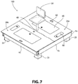
- FIG. 7 is a perspective view of the base of FIG. 3 in an assembled position
- FIG. 8 is a perspective view of the assembled base of FIG. 6 showing open compartments and a table;
- FIG. 9 is a perspective view of the assembled base of FIG. 6 with a sliding shooting rail and a plurality of camera mounts;
- FIG. 10A is a cross-sectional view of a floor panel of the base of FIG. 6 ;
- FIG. 10B is a cross-sectional view of a floor panel of the base of FIG. 6 including a frame to hold container in the floor panel;
- FIG. 11 is a side view of a bow holder housed within the assembled base of FIG. 6 ;
- FIG. 12 is a side view of a hunting blind and base positioned on an angled hillside.
- FIG. 13A is a perspective view of an insertion arrangement for a support member within an outer frame member of the base of FIG. 3 ;
- FIG. 13B is a side view of the insertion arrangement of FIG. 13A ;
- FIG. 14A is a perspective view of a securing arrangement for securing a hunting blind to the base of FIG. 3 ;
- FIG. 14B is a cross-sectional view of the securing arrangement of FIG. 14A ;
- FIG. 15 is a top perspective view of another embodiment of a base for supporting a sporting enclosure, such as a hunting blind;
- FIG. 16 is a bottom perspective view of the base of FIG. 15 ;
- FIG. 17 is an isolated view of one of the folding legs of the base of FIG. 15 ;
- FIG. 18 is a side view depicting the base of FIG. 15 installed on an inclined surface with a sporting enclosure supported thereon;
- FIG. 19 is a cross-sectional view of an adjustable leg assembly provided on the base of FIG. 15 .
- the present disclosure is directed to, in general, a hunting blind base and, in particular, to a portable hunting blind base including a frame having a plurality of storage compartments and other accessories to be utilized by a hunter when positioned within the hunting blind.
- a hunting blind base including a frame having a plurality of storage compartments and other accessories to be utilized by a hunter when positioned within the hunting blind.
- FIGS. 1-19 Certain preferred and non-limiting aspects of the components of the hunting blind base are illustrated in FIGS. 1-19 . While the following description references a hunting blind and hunter that uses the disclosed invention, it is to be understood that the present invention can also be used with other portable enclosures, including but not limited to, military applications in which a solider using a portable enclosure for sleeping or camping in an outdoor setting.
- a sporting enclosure which may be a hunting blind 200
- the sporting enclosure may be a hunting blind 200 , an ice fishing enclosure, a tent, or any other enclosure using in sporting activities.
- the base 100 may rest on a plurality of support members 2 a - 2 d .
- the hunting blind 200 may be any conventional hunting blind that is used by hunters.
- the hunting blind 200 may provide cover to hunters to reduce the chances of detection from animals, such as deer or water fowl.
- the hunting blind 200 may provide an inner space in which a hunter can sit or lie down while hunting.
- the hunting blind 200 may include a window for the hunter to look out of and to shoot from once an animal has been detected.
- the hunting blind 200 may be portable or a stationary structure that remains in place once assembled by the hunter.
- the hunting blind 200 may include a strap (not shown) on each bottom corner to connect to the base 100 .
- the plurality of support members 2 a - 2 d may be configured to hold the base 100 upon which the hunting blind 200 may be assembled.
- the base 100 is described in greater detail below.
- four support members 2 a - 2 d may be used to hold the base 100 .
- additional support members (not shown) may be used to add greater structural support to the base 100 and the hunting blind 200 .
- the support members 2 a - 2 d may be generally rectangular in shape.
- the support members 2 a - 2 d may have a pointed end to allow for easier insertion into the ground surface.
- the support members 2 a - 2 d may be made of wood.
- the support members 2 a - 2 d may be made of metal, plastic, or any other material sufficiently strong enough to hold the base 100 .
- the support members 2 a - 2 d may be water-proof so as not to deteriorate or rust from any moisture in the outdoor environment in which the base 100 and the hunting blind 200 have been assembled.
- the support members 2 a - 2 d may be hammered into a ground surface at a location the hunter decides to place the hunting blind 200 .
- the support members 2 a - 2 d may need to be inserted at different heights within the ground surface.
- two of the support members 2 a - 2 d may extend further from the ground surface on the lower side of the hill and the two remaining support members 2 a - 2 d may extend from the higher side of the hill to ensure that the base 100 rests on the support members 2 a - 2 d in a level position.
- each support member 2 a - 2 d may extend at different lengths from an uneven ground surface to provide a level platform to hold the base 100 .
- each support member 2 a - 2 d can adjust the height of each support member 2 a - 2 d to ensure that the top surface of each support member 2 a - 2 d is positioned at the same height to provide a level platform for the base 100 .
- the support members 2 a - 2 d may also allow a hunter to position the base 100 and the hunting blind 200 above a ground surface. For example, the hunter may insert the support members 2 a - 2 d in the muddy ground in a swamp. The base 100 and the hunting blind 200 may rest on the support members 2 a - 2 d above the swamp waters.
- the base 100 is configured to rest on the support members 2 a - 2 d once the support members 2 a - 2 d have been positioned in the ground surface at a level position.
- the base 100 may include four outer frame members 4 a - 4 d .
- the outer frame members 4 a - 4 d may be connected to move a generally square-shaped frame. It is also contemplated that the outer frame members 4 a 4 d may form other frames with different shapes, such as rectangular, triangular, or circular.
- Each outer frame member 4 a - 4 d may connect to two other outer frame members 4 a - 4 d .
- Each outer frame member 4 a - 4 d may include an inner connection member 6 a - 6 d to assist in placing the base 100 on the support members 2 a - 2 d .
- the inner connection members 6 a - 6 d may be U-shaped, with a two legs extending from an inner surface of the respective outer frame member 4 a - 4 d and another leg that perpendicularly extends between the first legs.
- each outer frame member 4 a - 4 d and each inner connection member 6 a - 6 d respectively, form a square-shaped enclosure configured to receive each respective support member 2 a - 2 d .
- Each enclosure includes a cap 8 a - 8 d that allows the base 100 to rest on a top surface of each support member 2 a - 2 d .
- the base 100 may be placed over the support members 2 a - 2 d such that the caps 8 a - 8 d rest on each respective support member 2 a - 2 d , which ensures the base 100 settles in a level position based on the insertion of the support members 2 a - 2 d into the ground surface.
- the hunter may set up different sets of support members 2 a - 2 d at multiple locations so that the hunter only needs to transport the base 100 and the hunting blind 200 between locations.
- each pair of outer frame members 4 a - 4 d may be connected in a similar fashion.
- the adjacent outer frame members 4 b , 4 c are positioned with an inner surface of one outer frame member 4 b abutting an end face of an adjacent outer frame member 4 c .
- An inner surface of an end of the outer frame member 4 c may include a pair of dovetail protrusions 9 a extending therefrom.
- One leg of the inner connection member 6 b may include corresponding dovetail recesses 9 b configured to receive the dovetail protrusions 9 a of the outer frame member 9 c .
- a dovetail shape is used for the protrusions 9 a and recesses 9 b , it is also contemplated that alternative shapes may also be used.
- the dovetail protrusions 9 a of the outer frame member 4 c may be inserted into the dovetail recesses 9 b defined in the inner connection member 6 b .
- the locking arrangement created by the dovetail protrusions 9 a and dovetail recesses 9 b prevents vertical movement of the outer frame members 4 b , 4 c relative to one another.
- the end face of the outer frame member 4 c may define at least two threaded apertures 10 a , 10 b .
- the outer frame member 4 b may also define at least two apertures through which a fastener 12 a , 12 b may extend.
- the fasteners 12 a , 12 b may include a threaded portion that extends into the threaded apertures 10 a , 10 b of the outer frame member 4 c .
- the fasteners 12 a , 12 b may also include a rotatable handle portion 14 a , 14 b .
- Each handle portion 14 a , 14 b may be rotatable either manually or through an automatic means to rotate and thread the fasteners 12 a , 12 b into the apertures 10 a , 10 b .
- the handle portions 14 a , 14 b are not being used to rotate the fasteners 12 a , 12 b , the handle portions can be snapped into place within a recess 16 a , 16 b defined in the outer frame member 4 b . In this manner, each pair of outer frame members 4 a - 4 d may be connected to one another to form the outer frame portion of the base 100 .
- each outer frame member 4 b , 4 c may include a corresponding plurality of teeth 9 c , 9 d that may be fit together to lock the outer frame members 4 b , 4 c .
- Each protruding tooth 9 c , 9 d may define an aperture to receive a removable pin 9 e once the teeth 9 c , 9 d have been fit together.
- the inner frame portion of the base 100 is described. After the outer frame portion of the base 100 has been assembled, the inner frame portion may be assembled.
- the inner frame portion may include at least two inner frame members 18 a , 18 b and at least two inner cross members 20 a - 20 c connected to the inner frame members 18 a , 18 b . Although a certain number of inner frame members and inner cross members are shown in the figures, it is to be understood that additional or fewer members may be provided to add or remove support to the base 100 as desired.
- Two of the outer frame members 4 b , 4 d may include at least two dovetail cuts 22 a , 22 b defined on an inner surface thereof.
- each inner frame member 18 a , 18 b may include a corresponding dovetail protrusion 24 a , 24 b configured for insertion into the respective dovetail cut 22 a , 22 b .
- a friction fit is formed between the outer frame members 4 b , 4 d and the inner frame members 18 a , 18 b .
- FIG 3 shows the inner frame members 18 a , 18 b connected to the outer frame members 4 b , 4 d , it is also contemplated that the inner frame members 18 a , 18 b may be connected to the outer frame members 4 a , 4 c .
- the inner cross members 20 a - 20 c may be connected in a dovetail arrangement with the inner frame members 18 a , 18 b .
- the inner cross members 20 a - 20 c may be connected to inner surfaces of the inner frame members 18 a , 18 b such that the inner cross members 20 a - 20 c are positioned between the inner frame members 18 a , 18 b .
- the inner cross members 20 a - 20 c may extend in a perpendicular direction to the inner frame members 18 a , 18 b .
- a seat base 26 may be attached to at least two of the inner cross members 20 b , 20 c .
- the seat base 26 is configured to receive and hold a removable seat on which the hunter may rest when hunting in the hunting blind 200 (described in greater detail below).
- each support member 2 a - 2 d may be positioned in a respective corner of the base 100 in a similar fashion.
- the inner connection member 6 b on the outer frame member 4 b may include a rotatable, biased cap 11 a that is configured to rotate downwards based on downward pressure on a top surface of the cap 11 a .
- a spring llb is provided in connection with the cap 11 a so that, after pressure has been relieved from the top surface of the cap 11 a , the cap 11 a is biased back into a resting position against a recess 11 c defined within the inner connection member 6 b . Therefore, in one aspect, the outer frame member 4 b , 4 c may be assembled and then the corresponding support member 2 c may be inserted into the inner connection member 6 b , thereby pushing the cap 11 a downwards. The individual can then apply pressure to the support member 2 c to insert the support member 2 c into the ground surface.
- the outer frame members 4 b , 4 c can then be lifted above the inserted support member 2 c , thereby allowing the cap 11 a to rotate back into its resting position against the recess 11 c based on the biasing force of the spring 11 b .
- the outer frame members 4 b , 4 c can then be lowered towards the support member 2 c to allow the cap 11 a to rest on the upper end of the support member 2 c.
- each floor panel 28 a , 28 b may have a more rigid base layer 29 and a padded, soundproof upper layer 31 .
- the upper layer 31 may be made of a cushioned material to dampen and suppress any movement of the hunter on the floor panels 28 a , 28 b .
- the floor panels 28 a , 28 b may be substantially mirror images of one another so that either floor panel 28 a , 28 b can be positioned on either portion of the base 100 .
- Each floor panel 28 a , 28 b is placed on one half of the base 100 to cover the upper surface of the base 100 .
- Each floor panel 28 a , 28 b may include a pair of locators 33 a , 33 b configured to assist in positioning the floor panel 28 a , 28 b on the outer frame members 4 a - 4 d .
- the locators 33 a , 33 b may be inserted into the inner connection members 6 a - 6 d to position the floor panels 28 a , 28 b in a correct orientation on the outer frame members 4 a - 4 d .
- the floor panels 28 a , 28 b should be rigid enough to allow a hunter to stand, lie, or sit on the floor panels 28 a , 28 b without cracking or bending, but should be light weight enough so that the floor panels 28 a , 28 b can be carried by the hunter with ease.
- the floor panels 28 a , 28 b may be rectangular in shape and may rest on the upper surface of the outer frame members 4 a - 4 d , the inner frame members 18 a , 18 b , and the inner cross members 20 a - 20 c .
- An inner edge 30 a , 30 b of one of the floor panels 28 a , 28 b may include a plurality of protrusions 32 that define an aperture which extends along a direction of the inner edge 30 a , 30 b .
- the protrusions 32 may be spaced along the inner edge 30 a , 30 b of the floor panel 28 a , 28 b .
- the inner edge 30 a , 30 b of the opposing floor panel 28 a , 28 b may include a plurality of recesses 34 configured to receive the protrusions 32 of the opposing floor panel 28 a , 28 b .
- An aperture 36 is defined in the inner edge 30 a and extends from a first end of the inner edge 30 a to an opposing second end of the inner edge 30 a .
- a rod 38 may be inserted into the aperture 36 and through the apertures defined by the protrusions 32 such that the floor panels 28 a , 28 b are held together on the base 100 .
- the rod connection between the floor panels 28 a , 28 b permits the floor panels 28 a , 28 b to rotate relative to one another.
- the floor panel 28 a may define an aperture 40 adjacent the inner edge 30 a of the floor panel 28 a .
- the aperture 40 may align with an aperture defined in the seat base 26 to allow a seat to be inserted through the aperture 40 and into the seat base 26 .
- the floor panel 28 a may also include a handle 42 defined adjacent an edge of the floor panel 28 a that is opposite the inner edge 30 a of the floor panel 28 a .
- the floor panel 28 a may also define an aperture 44 in the center of the floor panel 28 a .
- a lid 46 may be rotatably connected to the floor panel 28 a and may be configured to cover the aperture 44 . It is contemplated that the lid 46 may include a lock to protect any contents stored in a bin 48 held within the aperture 44 .
- the bin 48 may be removably positioned in the aperture 44 , such that, after the floor panel 28 a has been positioned on the base 100 , the bin 48 can be inserted into the aperture 44 and used to store hunting equipment, sleeping bags, clothing, blankets, or any similar types of items.
- the aperture 44 may define a first ledge 50 upon which the lid 46 may rest when covering the aperture 44 .
- the first ledge 50 may extend around the entire circumference of the aperture 44 .
- the aperture 44 may also define a second ledge 52 upon which the bin 48 may rest when inserted into the aperture 44 .
- the second ledge 52 may also extend around the entire circumference of the aperture 44 .
- the bin 48 may include a lip that extends outwardly to rest on the second ledge 52 .
- the second ledge 52 may be defined beneath the first ledge 50 , such that, when the lid 46 is closed over the aperture 44 , the lid 46 rests on the first ledge 50 . When the lid 46 is closed on the aperture 44 , a top surface of the lid 46 may be flush with a top surface of the floor panel 28 a.
- At least two sectioned apertures 54 a 54 b may be defined by a frame 54 c that is placed in a floor panel 28 b . It is contemplated, however, that the frame 54 c may define more than two apertures. Similar to the aperture 44 , the sectioned apertures 54 a , 54 b may define a first ledge configured to receive a lid and a second ledge to hold storage bins 56 a , 56 b in the section apertures 54 a , 54 b . The frame 54 c may rest on a ledge formed in the aperture 44 of the floor panel 28 b .
- One storage bin 56 a may be used as a collapsible cooler to store drinks, ice, food, or any item that should be kept at a colder temperature.
- the other storage bin 56 b may provide additional storage space for a hunter to hold clothing, hunting equipment, or any other items needed by the hunter while hunting.
- a seat 58 may be inserted through the aperture 40 and into the seat base 26 .
- the height of the seat 58 may be adjustable to permit use by a plurality of different hunters.
- the seat 58 may also be rotatable around an axis to allow the hunter to spin the seat 58 . It is also contemplated that the seat 58 may be collapsible for storage within one of the bins 48 , 56 a , 56 b.
- a table 60 may also be provided on the floor panel 28 a .
- the table 60 may include a table top 62 and a plurality of legs 64 that are attached to the table top 62 and the floor panel 28 a .
- the legs 64 may be hingedly connected in pair so that the legs 64 can be folded and unfolded to pull the table 60 out of the floor panel 28 a .
- a ring 66 may be provided in the table top 62 to allow the hunter to pull the table 60 out of the floor panel 28 a .
- the table 60 may be held within a recess 68 defined in the floor panel 28 a .
- a top surface of the table top 62 When held within the recess 68 , a top surface of the table top 62 may be flush with the upper surface of the floor panel 28 a .
- the hunter may pull the ring 66 to pull the table 60 out of the recess 68 .
- the legs 64 will unfold and extend upwards to an extended height such that the table top 62 is level with the seat 58 .
- the hunter can use the table 60 to hold drinks, ammunition, hunting equipment, binoculars, or any other equipment that is used during hunting.
- the table 60 can be pushed downwards so the legs 64 fold up and are stored within the recess 68 . It is also shown in FIG.
- a lock 65 a may be provided on the lid 46 of each floor panel 28 a , 28 b to permit the hunter to secure his/her equipment in the storage bins 48 , 56 a , 56 b . It is also contemplated that additional locks 65 b may be provided on the floor panels 28 a , 28 b to secure each floor panel 28 a , 28 b to each respective outer frame member 4 a - 4 d to prevent theft of the base 100 elements when the hunter leaves the base 100 in the field.
- a bow holder 70 provided with the base 100 is described.
- the bow holder 70 may be stored in a compartment 72 defined in one of the floor panels 28 a , 28 b .
- the compartment 72 may be covered with a lid 74 .
- the compartment 72 may be accessed by the hunter by opening the lid 74 .
- the hunter may then pull the bow holder 70 out of the compartment 72 .
- the bow holder 70 rotates upwardly out of the compartment 72 into an upright position.
- the bow holder 70 and compartment 72 may be provided adjacent the seat 58 to allow the hunter to reach or place his/her hunting bow on the bow holder 70 when sitting on the seat 58 .
- the bow holder 70 may include a straight base member and a hook member provided on an end of the straight base member.
- the bow holder 70 may be configured to hold a hunting bow in a ready position so that a hunter can quickly grab the hunting bow and bring the hunting bow to a firing position.
- a hunter's chance at taking a shot at an animal occurs very quickly.
- a hunter will often have to place his/her hunting bow on the ground in the hunting blind.
- the hunter will often have to reach down and/or away from his/her position to grab the hunting bow, often taking his/her eyes off of the animal moving in front of the hunting blind.
- the hunter's bow is easily accessible at a position adjacent to the hunter.
- the bow holder 70 holds the hunter's bow off of the ground surface and adjacent the hunter's hands to permit the hunter to quickly grab his/her bow and move it to a firing position.
- the bow holder 70 may be rotated downwardly into the compartment 72 and the lid 74 may be closed to store the bow holder 70 in the base 100 .
- a first camera mount 73 and a second camera mount 75 may be provided on the base 100 .
- the first camera mount 73 may be provided in a corner of the floor panel 28 b .
- the first camera mount 73 may be provided in front of the seat 58 .
- the second camera mount 75 may be positioned in a corner of the floor panel 28 a , behind the seat 58 . It is also contemplated that additional camera mounts may be provided on the floor panels 28 a , 28 b .
- Each camera mount 73 , 75 is configured to hold a camera that is directed towards the seat 58 to film the hunter during his/her hunt. These camera mounts 73 , 75 are especially useful for filming and production companies that film hunting-related shows and videos.
- the first camera mount 73 may be positioned lower relative to the floor panels 28 a , 28 b than the second camera mount 75 so as not to interfere with the hunter when shooting out of the hunting blind 200 .
- the first camera mount 73 may be provided to allow a camera to shoot a video or take photographs of the hunter while he/she is hunting.
- the second camera mount 75 may be provided to allow a camera to shoot a video or take photographs of the field of vision of the hunter out of the hunting blind 200 . It is also contemplated that the height of the camera mounts 73 , 75 may be adjustable. It is contemplated the camera mounts 73 , 75 may be configured to hold any type of video camera, including GoPro cameras or tail cams, or photographic camera.
- a shooting rail 76 is shown in connection with the base 100 .
- the shooting rail 76 may provide a rest on which the hunter can position his/her gun when sitting on the seat 58 in the hunting blind 200 .
- the hunter can rest his/her gun on the shooting rail 76 to level the gun to obtain a more accurate shot.
- the shooting rail 76 may be provided on either floor panel 28 a , 28 b .
- a shooting rail 76 is provided on each floor panel 28 a , 28 b .
- the shooting rail 76 may include two support members 78 a , 78 b and a resting member 80 .
- the support members 78 a , 78 b may extend substantially perpendicularly from the resting member 80 towards the floor panel 28 b .
- the shooting rail 76 may be provided in a storage position or a shooting position. In the storage position, the shooting rail 76 is stored within a recess 82 defined in the floor panel 28 b .
- the shape of the recess 82 may correspond to the shape of the shooting rail 76 .
- the hunter may pull the shooting rail 76 out of the recess 82 causing the shooting rail 76 to rotate upwards. Once the shooting rail 76 has been rotated upwards into an upright position, the shooting rail 76 is provided at the shooting position.
- the bottom ends of the support members 78 a , 78 b may drop into apertures (not shown) defined in the recess 82 to lock the shooting rail 76 in position.
- a brace 84 a , 84 b may be provided on a lower end of each support member 78 a , 78 b to add further support to the shooting rail 76 when positioned in the shooting position.
- the height of the shooting rail 76 may be adjustable.
- the support members 78 a , 78 b may be telescoping members that can extend and retract once in the shooting position to adjust the height of the resting member 80 relative to the hunter.
- the hunter may pull the resting member 80 upwards to pull the support members 78 a , 78 b out of the apertures defined in the recess 82 .
- the hunter may then rotate the shooting rail 76 downwards to lie in the recess 82 for storage.
- a securing arrangement 90 for securing the hunting blind 200 to the base 100 is described.
- the base 100 is configured to support varying sizes of hunting blinds. Based on the diameter of the hunting blind 200 , the securing arrangement 90 may be adjusted to secure the hunting blind 200 to the base 100 .
- the securing arrangement 90 may include a knob 91 , a threaded portion 92 extending from the knob 91 , a nut 93 threaded onto an end of the threaded portion 92 , and a hook 94 slidably provided on the threaded portion 92 .
- the knob 91 may be rotated to either hold the securing arrangement 90 in a channel 95 defined in the corners of the floor panels 28 a , 28 b or permit the securing arrangement 90 to slide along the channel 95 .
- the nut 93 may have a diameter that is wider than the diameter of a lower portion of the channel 95 to prevent the securing arrangement 90 from being pulled out of the channel 95 .
- the threaded portion 92 is rotated away from the nut 93 to allow the hook 94 to slide on the threaded portion 92 .
- a loop (not shown) from a corner of the hunting blind 200 may then be slid underneath the hook 94 .
- the knob 91 may be rotated in a second, opposing direction to move the threaded portion 92 into the nut 93 , thereby securing the hook 94 against the floor panel 28 a and the securing arrangement 90 within the channel 95 .
- the hook 94 secured against the floor panel 28 a
- the loops from the hunting blind 200 are held in place on the base 100 .
- the securing arrangement 90 may be slid inwards in the channel 95 to accommodate smaller hunting blinds, and the securing arrangement 90 may be slid outwards in the channel 95 to accommodate larger hunting blinds.
- the hunting blind 200 and base 100 assembly provide several benefits over conventional hunting blinds.
- the hunting blind 200 and base 100 increase the number of locations at which hunters can hunt.
- the floor panels 28 a , 28 b may be waterproof to keep the floor dry within the hunting blind 200 . Since the base 100 lifts the hunting blind 200 off of the ground surface and utilizes floor panels 28 a , 28 b , the interior of the hunting blind 200 is kept free of mud, dirt, and debris that can often move into conventional hunting blinds.
- the assembly protects the hunter from any animals that may move into the hunting blind 200 , such as rattlesnakes.
- the raised base 100 also permits the hunting blind 200 to be used in a swamp, where bucks and other animals are typically comfortable. Conventional hunting blinds do not have the necessary frame and floor platform to rise above the swamp waters.
- the base 100 is also easily assembled, thereby decreasing the assembly time of a conventional hunting blind or tree stand in half.
- the base 100 is also portable, permitting the hunter to easily disassemble the base 100 and move to another hunting location to spot animals.
- the bins 48 , 56 a , 56 b provided in the floor panels 28 a , 28 b provide increasing storage space for a hunter's hunting equipment, food, clothing, or sleeping equipment.
- the bins 48 , 56 a , 56 b permit the hunter to store his/her equipment under the floor panels 28 a , 28 b , thereby decreasing the amount of items that are left on top of the floor panels 28 a , 28 b that the hunter may trip over or move, thereby creating noise that may spook any nearby animals. Further, by keeping the floor panels 28 a , 28 b clear of equipment and debris, the hunter can comfortably lay on the floor panels 28 a , 28 b for a mid-day nap on all day hunts. Conventional hunting blinds do not typically include storage space for equipment. The seat 58 almost permits the hunter a 360 degree turning range, which allows the hunter to quietly rotate his/her view around the hunting blind 200 without creating excess noise.
- the table 60 and the bow holder 70 provide ready access for the hunter to his/her bow, binoculars, ammunition, range finder, food, calls, or any other equipment that may be held on the table 60 .
- the base 300 includes many similar features as the base 100 described above, but with slight variations to several features. It is also be understood that any of the features and accessories provided with the base 100 described above may be incorporated and used with the base 300 currently being described.
- the base 300 includes at least two separate sections 302 a , 302 b that are hingedly connected to one another. In one example, the sections 302 a , 302 b are connected via a hinge 304 at a top surface 306 a , 306 b of each section 302 a , 302 b . Any suitable hinge arrangement may be used to connect the two sections 302 a , 302 b .
- the sections 302 a , 302 b are configured to fold towards one another such that the top surfaces 306 a , 306 b of the sections 302 a , 302 b are brought in contact with one another.
- the base 300 is easily transported to a hunter's hunting destination or location.
- Each section 302 a , 302 b may include handles (not shown) defined therein so that a hunter can carry the base 300 when the sections 302 a , 302 b are folded or the hunter can hold the folded base 300 in a backpack or satchel to move the base 300 to the hunting destination or location.
- a locking arrangement may be provided on the sections 302 a , 302 b so that the sections 302 a , 302 b can be locked together when in the folded position.
- At least one level indicator 308 a , 308 b may be installed in each section 302 a , 302 b to assist a hunter in leveling the base 300 relative to an inclined surface.
- Each section 302 a , 302 b includes a floor panel 310 a , 310 b and a frame structure 312 a , 312 b .
- the floor panels 310 a , 310 b are substantially flat and provide support for a hunter to stand, sit, or lie down on the base 300 .
- the floor panels 310 a , 310 b may have a similar construction as the floor panels 28 a , 28 b described above.
- the frame structures 312 a , 312 b may be of any construction or configuration to provide adequate support for the base 300 to hold at least one hunter within a hunting blind provided on the base 300 .
- Each of the sections 302 a , 302 b may define at least one camera mount hole 314 to allow a hunter to position and move a mountable camera at/to different positions on the base 300 .
- each section 302 a , 302 b includes three separate mount holes 314 on two sides thereof. As shown in FIG. 15 , these mount holes 314 have an inclined receiving surface to assist in receiving any attachments that are inserted into the mount holes 314 .
- a removable table 60 , a bow holder 70 , a shooting rail 76 , or any other desired attachment may include cone-shaped locking elements that are received in the mount holes 314 .
- the attachments may be locked in the mount holes 314 via a snap-fit connection, a friction-fit connection, or any other connection to removably lock the attachment in the mount holes 314 . While FIG. 15 depicts the locking elements as cone-shape, it is contemplated that any sufficient locking element can be used to connect the attachments in the mount holes 314 .
- the attachments are removably held within the mount holes 314 so that the attachments can be disconnected from the mount holes 314 and stored in a storage bin when not in use.
- One section 302 a may include at least one chair mount hole 316 to receive a mountable/portable chair (not shown) for the hunter to sit on while hunting.
- two chair mount holes 316 are defined in the section 302 a so that, depending on whether the hunter is right-handed or left-handed, the chair can be mounted in the base 300 at an appropriate position to ensure the hunter has sufficient room for rotating a drawn bow or gun within the hunting blind.
- At least one section 302 b may include a lid 318 rotatably connected to the floor panel 310 b that permits access to a storage bin (not shown), such as the storage bin arrangement discussed above in connection with the base 100 .
- the lid 318 may include a lock (not shown) to ensure no items are stolen from the storage bin when the base 300 is left out in the open.
- each corner of the base 300 has an adjustable leg assembly 320 .
- the adjustable leg assemblies 320 permit a hunter to individually adjust the height of each adjustable leg assembly 320 so that the base 300 is provided at a level position when installed on an inclined surface.
- Each adjustable leg assembly 320 may include a single leg member 322 or a pair of telescoping leg members (not shown) that provides added height to the base 300 .
- the leg members 322 are movable within a bracket 324 rotatably held on the frame 312 a , 312 b of the base 300 .
- the leg members 322 are movable upward and downward within the brackets 324 to adjust the height position of the leg members 322 relative to the base 300 or an inclined surface.
- Each leg member 322 may include a base member 326 provided on a bottom end thereof.
- the base members 326 assist in placing the base 300 and hunting blind 200 at a swampy, muddy, flooded, or watery location that may not have such a solid surface on which to install the base 300 .
- the base members 326 help to distribute the weight of the base 300 and the hunt blind 200 (including the hunter standing therein) on the soggy, wet surface.
- the base members 326 include a plurality of apertures that allow the soggy, wet surface to pass through while the base members 326 rest on more solid ground.
- each of the adjustable leg assemblies 320 is rotatably between an extended position and a stored position.
- the adjustable leg assemblies 320 are positioned to hold the base 300 and hunting blind 200 on a surface.
- the adjustable leg assemblies 320 may also be rotated from the extended position to a stored position to store the adjustable leg assemblies 320 within the frames 312 a , 312 b to allow the section 302 a , 302 b to be folded and transported by a hunter.
- the bracket 324 is held within a slot 328 defined within the frame 312 a , 312 b .
- the slot 328 permits rotation of the bracket 324 and leg member 322 underneath the frame 312 a , 312 b .
- the bracket 324 is also attached at least one retracting member 330 rotatably held on an underside of the floor panel 310 a , 310 b .
- at least two retractable members 330 are connected to the bracket 324 and the floor panel 310 a , 310 b .
- the retractable members 330 include two folding members that move between an extended position and a retracted position.
- the retractable member 330 is a hydraulic cylinder or a spring-biased cylinder that can assist in locking the bracket 324 in the extended or stored position.
- the retractable member 330 also extends to the extended position. It is contemplated that locking arrangements (not shown) may be provided on the underside of the floor panels 310 a , 310 b to lock the leg members 322 in the stored position during transport of the base 300 . As shown in FIG. 18 , after the base 300 and hunting blind 200 have been installed at the hunting location, a skirt 332 may be attached to the outer side of the sections 302 a , 302 b by any suitable connection methods (i.e., hooks, hook-and-loops fasteners, such as Velcro, snap buttons, buttons, zippers, or adhesive).
- any suitable connection methods i.e., hooks, hook-and-loops fasteners, such as Velcro, snap buttons, buttons, zippers, or adhesive.
- the skirt 332 may have a camouflage pattern to conceal the leg members 322 of the base 300 when installed on the surface. It is contemplated that any suitable camouflage pattern may be used and that the skirt 332 may include a different camouflage pattern on each side thereof so that the skirt 332 is reversible to accommodate different hunting locations.
- an actuating button 334 is provided on the bracket 324 to allow for each adjustment of the height of the leg member 322 .
- the actuating button 334 extends from an outer surface of the bracket 324 and extends through the bracket 324 to a cavity defined in the bracket 324 to receive the leg member 322 .
- One end of the actuating button 334 includes a pin 336 that is movable between an engaged and disengaged position with a particular hole 338 defined in the leg member 322 .
- the actuating button 334 is spring-biased such that the pin 336 is biased to the engaged position.
- each leg member 322 defines a plurality of holes 338 that correspond to different height positions for the leg member 322 .
- the pin 336 of the actuating button 334 is insertable into each of the holes 338 to lock the leg member 322 at a particular height relative to the surface. To adjust the height of the leg member 322 , a user will push the actuating button 334 with a force F towards the bracket 324 .
- each adjustable leg assembly 320 can be adjusted in this manner to ensure the base 300 is positioned level relative to an inclined surface.
Landscapes
- Engineering & Computer Science (AREA)
- Life Sciences & Earth Sciences (AREA)
- General Engineering & Computer Science (AREA)
- Architecture (AREA)
- Environmental Sciences (AREA)
- Zoology (AREA)
- Wood Science & Technology (AREA)
- Pest Control & Pesticides (AREA)
- Insects & Arthropods (AREA)
- Civil Engineering (AREA)
- Structural Engineering (AREA)
- Special Chairs (AREA)
- Operating, Guiding And Securing Of Roll- Type Closing Members (AREA)
Abstract
Description
Claims (25)
Priority Applications (3)
| Application Number | Priority Date | Filing Date | Title |
|---|---|---|---|
| US15/650,206 US10645920B2 (en) | 2016-07-14 | 2017-07-14 | Portable hunting blind base and accessories therefor |
| US16/865,582 US11006625B2 (en) | 2016-07-14 | 2020-05-04 | Portable hunting blind base and accessories therefor |
| US17/235,550 US11570980B2 (en) | 2016-07-14 | 2021-04-20 | Portable hunting blind base and accessories therefor |
Applications Claiming Priority (2)
| Application Number | Priority Date | Filing Date | Title |
|---|---|---|---|
| US201662362361P | 2016-07-14 | 2016-07-14 | |
| US15/650,206 US10645920B2 (en) | 2016-07-14 | 2017-07-14 | Portable hunting blind base and accessories therefor |
Related Child Applications (1)
| Application Number | Title | Priority Date | Filing Date |
|---|---|---|---|
| US16/865,582 Continuation US11006625B2 (en) | 2016-07-14 | 2020-05-04 | Portable hunting blind base and accessories therefor |
Publications (2)
| Publication Number | Publication Date |
|---|---|
| US20180014529A1 US20180014529A1 (en) | 2018-01-18 |
| US10645920B2 true US10645920B2 (en) | 2020-05-12 |
Family
ID=60942003
Family Applications (3)
| Application Number | Title | Priority Date | Filing Date |
|---|---|---|---|
| US15/650,206 Active - Reinstated US10645920B2 (en) | 2016-07-14 | 2017-07-14 | Portable hunting blind base and accessories therefor |
| US16/865,582 Active US11006625B2 (en) | 2016-07-14 | 2020-05-04 | Portable hunting blind base and accessories therefor |
| US17/235,550 Active 2037-07-18 US11570980B2 (en) | 2016-07-14 | 2021-04-20 | Portable hunting blind base and accessories therefor |
Family Applications After (2)
| Application Number | Title | Priority Date | Filing Date |
|---|---|---|---|
| US16/865,582 Active US11006625B2 (en) | 2016-07-14 | 2020-05-04 | Portable hunting blind base and accessories therefor |
| US17/235,550 Active 2037-07-18 US11570980B2 (en) | 2016-07-14 | 2021-04-20 | Portable hunting blind base and accessories therefor |
Country Status (2)
| Country | Link |
|---|---|
| US (3) | US10645920B2 (en) |
| CA (1) | CA2973252A1 (en) |
Cited By (4)
| Publication number | Priority date | Publication date | Assignee | Title |
|---|---|---|---|---|
| WO2022155571A1 (en) * | 2021-01-18 | 2022-07-21 | Under Blind, Inc. | Portable hunting blind base and accessories therefor, including a wheeled arrangement |
| US20220304295A1 (en) * | 2021-03-26 | 2022-09-29 | Andy Lopez | Fishing platform |
| US11683597B1 (en) * | 2022-07-07 | 2023-06-20 | The Florida International University Board Of Trustees | Systems and methods for multi-directional imaging during indentation |
| US20230200543A1 (en) * | 2021-12-27 | 2023-06-29 | Jeffrey Ciolino | Yoga bench |
Families Citing this family (12)
| Publication number | Priority date | Publication date | Assignee | Title |
|---|---|---|---|---|
| CA2973252A1 (en) | 2016-07-14 | 2018-01-14 | Christopher J. Litwin | Portable hunting blind base and accessories therefor |
| US11013329B2 (en) * | 2017-08-10 | 2021-05-25 | Huntwise, Inc. | Integrated blind seat system |
| US10722021B2 (en) | 2018-02-07 | 2020-07-28 | Perry Fant | Field pack |
| US10849321B2 (en) * | 2018-03-11 | 2020-12-01 | Tactacam LLC | Portable ground blind stand with case |
| US10542742B1 (en) * | 2018-07-16 | 2020-01-28 | Mark Ellinghuysen | Portable game blind |
| US11280108B1 (en) * | 2019-02-05 | 2022-03-22 | Shawn Szepi | Water diverting ground platform |
| US11821227B1 (en) * | 2020-03-12 | 2023-11-21 | Gregory Burnett Mickens | One-person shelter |
| US20230024026A1 (en) * | 2021-07-26 | 2023-01-26 | Abc Technologies Inc. | Pickup cargo bed storage system |
| US20230250668A1 (en) * | 2022-02-07 | 2023-08-10 | John R. Edwards, JR. | Portable Support Platform |
| CN114794723A (en) * | 2022-04-19 | 2022-07-29 | 广东工商职业技术大学 | Information operation and maintenance device for mass data and use method thereof |
| JP7651534B2 (en) * | 2022-09-29 | 2025-03-26 | 本田技研工業株式会社 | Frame Structure |
| US12338648B2 (en) * | 2022-11-07 | 2025-06-24 | Sean Dehlinger | Modular tent floor assembly |
Citations (80)
| Publication number | Priority date | Publication date | Assignee | Title |
|---|---|---|---|---|
| US485855A (en) * | 1892-11-08 | Folding table | ||
| US622284A (en) * | 1899-04-04 | Dust-receptacle | ||
| US891266A (en) | 1907-07-29 | 1908-06-23 | James R Koen | Knockdown chair. |
| US928726A (en) * | 1908-12-24 | 1909-07-20 | Guy Henry Witthaus | Disappearing table. |
| US1039868A (en) * | 1911-04-24 | 1912-10-01 | Fremont L Whitney | Foldable table-leg. |
| US1205569A (en) * | 1914-11-07 | 1916-11-21 | H W Schwimmer Company | Electrically-heated chocolate-table. |
| US1429969A (en) * | 1921-12-10 | 1922-09-26 | Everett C Palmer | Pivoted folding table leg |
| US1721198A (en) * | 1927-11-30 | 1929-07-16 | Joseph Cahen | Folding camp house |
| US2024431A (en) * | 1932-05-12 | 1935-12-17 | Gustave F Corduan | Card table |
| US2473076A (en) * | 1947-06-27 | 1949-06-14 | Scheibner Carl | Collapsible structure for ice fishing |
| GB640937A (en) * | 1947-07-24 | 1950-08-02 | Mabel Frances Sydney Smith | Improvements relating to collapsible tables |
| FR1009968A (en) * | 1948-07-16 | 1952-06-05 | Folding table or similar | |
| US2717160A (en) * | 1954-02-03 | 1955-09-06 | Farmgard Products Company | Fishing shelter |
| US2804083A (en) * | 1954-11-04 | 1957-08-27 | Wieber Andrew John | Portable foldable enclosure |
| US2883713A (en) * | 1957-09-30 | 1959-04-28 | Luward Corp | Portable foldable cabin |
| US2905513A (en) * | 1956-05-23 | 1959-09-22 | Isabelle M Kane | Collapsible umbrella-type beach table |
| US3095231A (en) * | 1961-09-29 | 1963-06-25 | Lloyd E Reed | Collapsible tent and trailer |
| US3223055A (en) | 1964-05-11 | 1965-12-14 | August J Braun | Chair adaptors |
| US3289787A (en) * | 1964-07-10 | 1966-12-06 | Thad M Mcswain | Collapsible hunting shelter |
| US3330081A (en) * | 1964-09-14 | 1967-07-11 | Tasa Coal Company | Portable shelter with panel storage floor members |
| US3605140A (en) * | 1969-03-10 | 1971-09-20 | Vance R Wanner | Portable bunk tent and bunk tent combination |
| US3739536A (en) | 1971-01-13 | 1973-06-19 | H Ward | Knock-down shelter |
| US3826270A (en) * | 1973-02-14 | 1974-07-30 | H Hentges | Collapsible ice fishing house |
| US3844300A (en) * | 1972-10-19 | 1974-10-29 | R Sanders | Tent and enclosure therefor |
| US3878797A (en) * | 1973-10-03 | 1975-04-22 | Marilyn Patterson | Pattern table |
| US3985387A (en) | 1975-05-02 | 1976-10-12 | Rischar Bernard J | Back pack chair |
| US4101163A (en) | 1977-02-16 | 1978-07-18 | Morin Robert J | Collapsible chair |
| USD260674S (en) * | 1979-12-13 | 1981-09-08 | Simmons Bruce D | Archer's bow holder |
| US4317519A (en) | 1980-11-03 | 1982-03-02 | Leroy Talley | Portable shoeshine kit |
| US4471793A (en) * | 1982-11-22 | 1984-09-18 | Leonel Cattaneo | Combination collapsible tent and foldable storage case |
| US4625655A (en) * | 1984-08-09 | 1986-12-02 | Harold Brickman | Foldable table having storage capabilities |
| US4658759A (en) * | 1985-07-11 | 1987-04-21 | Brown Elizabeth A | Adjustable dog feeding tray means |
| US4830036A (en) * | 1987-10-30 | 1989-05-16 | Sanders Charles W | Portable car top tent |
| US4926893A (en) | 1989-06-13 | 1990-05-22 | Rick Klopfenstein | Portable, collapsible ice fishing shelter |
| US5069142A (en) * | 1988-07-27 | 1991-12-03 | Matre Vigbj Phi Rn | Collapsible table |
| US5327838A (en) * | 1993-05-12 | 1994-07-12 | Beltman Charles H | Play table with self-contained storage |
| US5341588A (en) | 1993-09-24 | 1994-08-30 | Quentin Lizotte | Portable ice fishing hut |
| US5345881A (en) * | 1991-12-19 | 1994-09-13 | Howe Furniture Corporation | Folding table mechanism |
| US5368126A (en) * | 1993-03-29 | 1994-11-29 | Woodward; Wilbur W. | Adjustable work platform |
| US5371966A (en) * | 1992-03-04 | 1994-12-13 | Hall; Rocky A. | Cylindrical hunting blind |
| US5375905A (en) * | 1993-08-23 | 1994-12-27 | Flitter; Donald E. | Portable ground platform seat |
| US5377657A (en) * | 1991-12-03 | 1995-01-03 | Foster; Gary D. | Archery bow holder |
| US5414949A (en) * | 1994-08-10 | 1995-05-16 | Peebles; Kenneth E. | Portable shooting stand |
| US5622198A (en) | 1996-01-05 | 1997-04-22 | Elsinger; Raymond A. | Portable collapsible shelter |
| USD382035S (en) * | 1996-02-05 | 1997-08-05 | Swicegood Marcus S | Gun rest |
| US5778800A (en) * | 1997-04-02 | 1998-07-14 | Liang; Chin-Chun | Folding collapsible mantel |
| US5979725A (en) * | 1998-01-16 | 1999-11-09 | Lehrman; Mark A. | Multi-compartment organizer for minivan |
| US6192909B1 (en) * | 1999-06-28 | 2001-02-27 | Matthew Strausser | Collapsible all-terrain shelter and frame |
| US6289824B1 (en) | 2000-04-17 | 2001-09-18 | Paul Oliver Parker | Collapsible jobsite plan table |
| US6305117B1 (en) * | 1998-11-24 | 2001-10-23 | Lawrence R. Hales, Sr. | Support for rifle sighting |
| USD450959S1 (en) * | 2000-08-17 | 2001-11-27 | Herman Miller, Inc. | Tabletop |
| CA2389102A1 (en) * | 2002-06-13 | 2003-12-13 | Donald Campbell | Movable hut |
| US6892651B1 (en) | 2002-12-16 | 2005-05-17 | Barbara Van Reed | Modular storage platform system |
| US20050265711A1 (en) * | 2004-05-27 | 2005-12-01 | Heibel Thomas S | Camera Mount |
| US20060254480A1 (en) | 2005-05-11 | 2006-11-16 | Efraim Haimoff | Multi-shelf collapsible table |
| US20070056482A1 (en) * | 2004-03-17 | 2007-03-15 | Elgin Robinson | Foldable table with waste receptacles |
| US7314199B1 (en) | 2004-12-31 | 2008-01-01 | Ward David L | Folding archery bow stand |
| US20080047188A1 (en) * | 2004-05-10 | 2008-02-28 | Mats Lindstrom | Height-Adjustable and Foldable Gun Rest |
| US20080061576A1 (en) * | 2006-09-11 | 2008-03-13 | Honda Motor Co., Ltd. | Convenient storage solutions in cargo area |
| US20090114689A1 (en) * | 2007-11-05 | 2009-05-07 | Hord Richard W | Removable storage tub apparatus for a marine vessel |
| US20100018130A1 (en) * | 2005-06-29 | 2010-01-28 | Michael Lopez | Collapsible Buildings And Building Modules |
| US20100123067A1 (en) * | 2008-11-17 | 2010-05-20 | John Cardenas | Bow caddy |
| US20100127032A1 (en) * | 2008-11-21 | 2010-05-27 | Schubring James D | Removable in-floor storage device |
| US7726080B2 (en) * | 2008-01-04 | 2010-06-01 | Rebecca Lynne Hyndman | Under-floor storage |
| US20100162961A1 (en) * | 2008-12-29 | 2010-07-01 | Craig Hove | Pet Feeder |
| USD619671S1 (en) | 2009-03-20 | 2010-07-13 | David Jenkins | Support stand for a hunting bow |
| US8220197B1 (en) * | 2008-04-22 | 2012-07-17 | Pray Thomas J | Collapsible fly trap |
| US20120211306A1 (en) * | 2011-02-22 | 2012-08-23 | Cretice Gary Benefield | Tree stand adapted to create a spiral step around a tree |
| US20120211042A1 (en) * | 2011-02-22 | 2012-08-23 | Richter Scott J | Portable ice fishing or hunting shanty |
| US20130145671A1 (en) * | 2011-12-12 | 2013-06-13 | Bruce G C Cavell | Gun and Bow Rest |
| US8671963B2 (en) * | 2009-07-25 | 2014-03-18 | DA DING ENERGY Co., Ltd. | Overhead combined tent structure |
| US8761963B2 (en) * | 2010-12-01 | 2014-06-24 | John Hinkel, III | Wheelchair guiding |
| US20140245933A1 (en) | 2013-03-03 | 2014-09-04 | Christi Ann Leslie | Mobile Under-bed Storage Platform |
| US8857346B2 (en) * | 2011-02-01 | 2014-10-14 | Cindy Khanjian | Easy party table |
| US8857926B2 (en) * | 2011-01-11 | 2014-10-14 | Azek Building Products, Inc. | Deck storage bin system |
| US20150027067A1 (en) * | 2013-07-24 | 2015-01-29 | Taxa, Inc. | Compact combined habitation module and utility rack with multiple deployment modes |
| CA2973252A1 (en) * | 2016-07-14 | 2018-01-14 | Christopher J. Litwin | Portable hunting blind base and accessories therefor |
| US20180155921A1 (en) * | 2016-12-06 | 2018-06-07 | Stephen T. Evert | Novel Personal, Relocatable Protective Enclosure |
| US10117513B1 (en) * | 2013-10-17 | 2018-11-06 | Grant M. J. Tolentino | Portable chafing and serving table |
| US20190274298A1 (en) * | 2018-03-11 | 2019-09-12 | Tactacam LLC | Portable ground blind stand |
Family Cites Families (22)
| Publication number | Priority date | Publication date | Assignee | Title |
|---|---|---|---|---|
| FR2028600A5 (en) | 1969-01-03 | 1970-10-09 | Thomson Brandt Csf | |
| US4739580A (en) * | 1985-04-01 | 1988-04-26 | Simmons Jesse K | Portable table with frictionally engagable leg locking mechanism |
| USD307365S (en) * | 1986-12-22 | 1990-04-24 | Dry James R | Fish cleaning table |
| US4733898A (en) * | 1987-03-09 | 1988-03-29 | Williams Scottie D | Pickup-bed secure storage unit |
| US4832242A (en) * | 1987-10-09 | 1989-05-23 | Leek Thomas R | Automobile trunk organizer |
| US4927128A (en) * | 1989-09-08 | 1990-05-22 | Brian Lynwood O | Sliding leg bodywork table |
| US5060580A (en) * | 1990-04-06 | 1991-10-29 | Shaw William L | Food management table |
| US5568890A (en) * | 1995-08-21 | 1996-10-29 | Magee; Jack C. | Vehicle storage cabinet |
| US6241137B1 (en) * | 1997-04-14 | 2001-06-05 | Caven W. Corr | Removable deck/platform apparatus with storage access for sport utility vehicles, pickup trucks and mini vans |
| US6119812A (en) * | 1999-03-15 | 2000-09-19 | Chin; Harvey | Collapsible surf stand |
| US6662732B2 (en) * | 2000-08-17 | 2003-12-16 | Herman Miller, Inc. | Modular desk |
| US6701853B1 (en) * | 2002-09-03 | 2004-03-09 | Sunny Hwang | Height-adjustable table |
| WO2007006399A1 (en) * | 2005-07-13 | 2007-01-18 | Roche Diagnostics Gmbh | Lancet device |
| US20090096239A1 (en) * | 2007-06-06 | 2009-04-16 | Dave Martin | Vehicle utility deck and storage |
| US8015928B2 (en) * | 2008-12-16 | 2011-09-13 | Hsing-Hui Chen | Foldable table having multiple functions |
| US8689705B2 (en) * | 2010-06-02 | 2014-04-08 | Steelcase, Inc. | Reconfigurable table assemblies |
| US8347790B1 (en) * | 2010-07-26 | 2013-01-08 | Maiers Russell J | Multi-purpose table |
| US9259094B1 (en) * | 2013-01-05 | 2016-02-16 | Ira D. McCauley | Combination ground blind, water blind and transportation crate |
| US10035255B2 (en) * | 2016-09-28 | 2018-07-31 | Owen Cindric | Portable workbench assembly |
| US11168832B2 (en) * | 2018-05-08 | 2021-11-09 | Damon A. Carter, SR. | Mobile phone support arrangement |
| WO2020069237A1 (en) * | 2018-09-28 | 2020-04-02 | Peter Hurley | Multi-purpose portable platform stage |
| US11102973B2 (en) * | 2019-04-12 | 2021-08-31 | Val Neshyba | Hunting stand apparatus and method |
-
2017
- 2017-07-14 CA CA2973252A patent/CA2973252A1/en active Pending
- 2017-07-14 US US15/650,206 patent/US10645920B2/en active Active - Reinstated
-
2020
- 2020-05-04 US US16/865,582 patent/US11006625B2/en active Active
-
2021
- 2021-04-20 US US17/235,550 patent/US11570980B2/en active Active
Patent Citations (80)
| Publication number | Priority date | Publication date | Assignee | Title |
|---|---|---|---|---|
| US485855A (en) * | 1892-11-08 | Folding table | ||
| US622284A (en) * | 1899-04-04 | Dust-receptacle | ||
| US891266A (en) | 1907-07-29 | 1908-06-23 | James R Koen | Knockdown chair. |
| US928726A (en) * | 1908-12-24 | 1909-07-20 | Guy Henry Witthaus | Disappearing table. |
| US1039868A (en) * | 1911-04-24 | 1912-10-01 | Fremont L Whitney | Foldable table-leg. |
| US1205569A (en) * | 1914-11-07 | 1916-11-21 | H W Schwimmer Company | Electrically-heated chocolate-table. |
| US1429969A (en) * | 1921-12-10 | 1922-09-26 | Everett C Palmer | Pivoted folding table leg |
| US1721198A (en) * | 1927-11-30 | 1929-07-16 | Joseph Cahen | Folding camp house |
| US2024431A (en) * | 1932-05-12 | 1935-12-17 | Gustave F Corduan | Card table |
| US2473076A (en) * | 1947-06-27 | 1949-06-14 | Scheibner Carl | Collapsible structure for ice fishing |
| GB640937A (en) * | 1947-07-24 | 1950-08-02 | Mabel Frances Sydney Smith | Improvements relating to collapsible tables |
| FR1009968A (en) * | 1948-07-16 | 1952-06-05 | Folding table or similar | |
| US2717160A (en) * | 1954-02-03 | 1955-09-06 | Farmgard Products Company | Fishing shelter |
| US2804083A (en) * | 1954-11-04 | 1957-08-27 | Wieber Andrew John | Portable foldable enclosure |
| US2905513A (en) * | 1956-05-23 | 1959-09-22 | Isabelle M Kane | Collapsible umbrella-type beach table |
| US2883713A (en) * | 1957-09-30 | 1959-04-28 | Luward Corp | Portable foldable cabin |
| US3095231A (en) * | 1961-09-29 | 1963-06-25 | Lloyd E Reed | Collapsible tent and trailer |
| US3223055A (en) | 1964-05-11 | 1965-12-14 | August J Braun | Chair adaptors |
| US3289787A (en) * | 1964-07-10 | 1966-12-06 | Thad M Mcswain | Collapsible hunting shelter |
| US3330081A (en) * | 1964-09-14 | 1967-07-11 | Tasa Coal Company | Portable shelter with panel storage floor members |
| US3605140A (en) * | 1969-03-10 | 1971-09-20 | Vance R Wanner | Portable bunk tent and bunk tent combination |
| US3739536A (en) | 1971-01-13 | 1973-06-19 | H Ward | Knock-down shelter |
| US3844300A (en) * | 1972-10-19 | 1974-10-29 | R Sanders | Tent and enclosure therefor |
| US3826270A (en) * | 1973-02-14 | 1974-07-30 | H Hentges | Collapsible ice fishing house |
| US3878797A (en) * | 1973-10-03 | 1975-04-22 | Marilyn Patterson | Pattern table |
| US3985387A (en) | 1975-05-02 | 1976-10-12 | Rischar Bernard J | Back pack chair |
| US4101163A (en) | 1977-02-16 | 1978-07-18 | Morin Robert J | Collapsible chair |
| USD260674S (en) * | 1979-12-13 | 1981-09-08 | Simmons Bruce D | Archer's bow holder |
| US4317519A (en) | 1980-11-03 | 1982-03-02 | Leroy Talley | Portable shoeshine kit |
| US4471793A (en) * | 1982-11-22 | 1984-09-18 | Leonel Cattaneo | Combination collapsible tent and foldable storage case |
| US4625655A (en) * | 1984-08-09 | 1986-12-02 | Harold Brickman | Foldable table having storage capabilities |
| US4658759A (en) * | 1985-07-11 | 1987-04-21 | Brown Elizabeth A | Adjustable dog feeding tray means |
| US4830036A (en) * | 1987-10-30 | 1989-05-16 | Sanders Charles W | Portable car top tent |
| US5069142A (en) * | 1988-07-27 | 1991-12-03 | Matre Vigbj Phi Rn | Collapsible table |
| US4926893A (en) | 1989-06-13 | 1990-05-22 | Rick Klopfenstein | Portable, collapsible ice fishing shelter |
| US5377657A (en) * | 1991-12-03 | 1995-01-03 | Foster; Gary D. | Archery bow holder |
| US5345881A (en) * | 1991-12-19 | 1994-09-13 | Howe Furniture Corporation | Folding table mechanism |
| US5371966A (en) * | 1992-03-04 | 1994-12-13 | Hall; Rocky A. | Cylindrical hunting blind |
| US5368126A (en) * | 1993-03-29 | 1994-11-29 | Woodward; Wilbur W. | Adjustable work platform |
| US5327838A (en) * | 1993-05-12 | 1994-07-12 | Beltman Charles H | Play table with self-contained storage |
| US5375905A (en) * | 1993-08-23 | 1994-12-27 | Flitter; Donald E. | Portable ground platform seat |
| US5341588A (en) | 1993-09-24 | 1994-08-30 | Quentin Lizotte | Portable ice fishing hut |
| US5414949A (en) * | 1994-08-10 | 1995-05-16 | Peebles; Kenneth E. | Portable shooting stand |
| US5622198A (en) | 1996-01-05 | 1997-04-22 | Elsinger; Raymond A. | Portable collapsible shelter |
| USD382035S (en) * | 1996-02-05 | 1997-08-05 | Swicegood Marcus S | Gun rest |
| US5778800A (en) * | 1997-04-02 | 1998-07-14 | Liang; Chin-Chun | Folding collapsible mantel |
| US5979725A (en) * | 1998-01-16 | 1999-11-09 | Lehrman; Mark A. | Multi-compartment organizer for minivan |
| US6305117B1 (en) * | 1998-11-24 | 2001-10-23 | Lawrence R. Hales, Sr. | Support for rifle sighting |
| US6192909B1 (en) * | 1999-06-28 | 2001-02-27 | Matthew Strausser | Collapsible all-terrain shelter and frame |
| US6289824B1 (en) | 2000-04-17 | 2001-09-18 | Paul Oliver Parker | Collapsible jobsite plan table |
| USD450959S1 (en) * | 2000-08-17 | 2001-11-27 | Herman Miller, Inc. | Tabletop |
| CA2389102A1 (en) * | 2002-06-13 | 2003-12-13 | Donald Campbell | Movable hut |
| US6892651B1 (en) | 2002-12-16 | 2005-05-17 | Barbara Van Reed | Modular storage platform system |
| US20070056482A1 (en) * | 2004-03-17 | 2007-03-15 | Elgin Robinson | Foldable table with waste receptacles |
| US20080047188A1 (en) * | 2004-05-10 | 2008-02-28 | Mats Lindstrom | Height-Adjustable and Foldable Gun Rest |
| US20050265711A1 (en) * | 2004-05-27 | 2005-12-01 | Heibel Thomas S | Camera Mount |
| US7314199B1 (en) | 2004-12-31 | 2008-01-01 | Ward David L | Folding archery bow stand |
| US20060254480A1 (en) | 2005-05-11 | 2006-11-16 | Efraim Haimoff | Multi-shelf collapsible table |
| US20100018130A1 (en) * | 2005-06-29 | 2010-01-28 | Michael Lopez | Collapsible Buildings And Building Modules |
| US20080061576A1 (en) * | 2006-09-11 | 2008-03-13 | Honda Motor Co., Ltd. | Convenient storage solutions in cargo area |
| US20090114689A1 (en) * | 2007-11-05 | 2009-05-07 | Hord Richard W | Removable storage tub apparatus for a marine vessel |
| US7726080B2 (en) * | 2008-01-04 | 2010-06-01 | Rebecca Lynne Hyndman | Under-floor storage |
| US8220197B1 (en) * | 2008-04-22 | 2012-07-17 | Pray Thomas J | Collapsible fly trap |
| US20100123067A1 (en) * | 2008-11-17 | 2010-05-20 | John Cardenas | Bow caddy |
| US20100127032A1 (en) * | 2008-11-21 | 2010-05-27 | Schubring James D | Removable in-floor storage device |
| US20100162961A1 (en) * | 2008-12-29 | 2010-07-01 | Craig Hove | Pet Feeder |
| USD619671S1 (en) | 2009-03-20 | 2010-07-13 | David Jenkins | Support stand for a hunting bow |
| US8671963B2 (en) * | 2009-07-25 | 2014-03-18 | DA DING ENERGY Co., Ltd. | Overhead combined tent structure |
| US8761963B2 (en) * | 2010-12-01 | 2014-06-24 | John Hinkel, III | Wheelchair guiding |
| US8857926B2 (en) * | 2011-01-11 | 2014-10-14 | Azek Building Products, Inc. | Deck storage bin system |
| US8857346B2 (en) * | 2011-02-01 | 2014-10-14 | Cindy Khanjian | Easy party table |
| US20120211042A1 (en) * | 2011-02-22 | 2012-08-23 | Richter Scott J | Portable ice fishing or hunting shanty |
| US20120211306A1 (en) * | 2011-02-22 | 2012-08-23 | Cretice Gary Benefield | Tree stand adapted to create a spiral step around a tree |
| US20130145671A1 (en) * | 2011-12-12 | 2013-06-13 | Bruce G C Cavell | Gun and Bow Rest |
| US20140245933A1 (en) | 2013-03-03 | 2014-09-04 | Christi Ann Leslie | Mobile Under-bed Storage Platform |
| US20150027067A1 (en) * | 2013-07-24 | 2015-01-29 | Taxa, Inc. | Compact combined habitation module and utility rack with multiple deployment modes |
| US10117513B1 (en) * | 2013-10-17 | 2018-11-06 | Grant M. J. Tolentino | Portable chafing and serving table |
| CA2973252A1 (en) * | 2016-07-14 | 2018-01-14 | Christopher J. Litwin | Portable hunting blind base and accessories therefor |
| US20180155921A1 (en) * | 2016-12-06 | 2018-06-07 | Stephen T. Evert | Novel Personal, Relocatable Protective Enclosure |
| US20190274298A1 (en) * | 2018-03-11 | 2019-09-12 | Tactacam LLC | Portable ground blind stand |
Cited By (6)
| Publication number | Priority date | Publication date | Assignee | Title |
|---|---|---|---|---|
| WO2022155571A1 (en) * | 2021-01-18 | 2022-07-21 | Under Blind, Inc. | Portable hunting blind base and accessories therefor, including a wheeled arrangement |
| US20240081317A1 (en) * | 2021-01-18 | 2024-03-14 | Christopher J. Litwin | Portable Hunting Blind Base and Accessories Therefor, Including a Wheeled Arrangement |
| US20220304295A1 (en) * | 2021-03-26 | 2022-09-29 | Andy Lopez | Fishing platform |
| US11528899B2 (en) * | 2021-03-26 | 2022-12-20 | Andy Lopez | Fishing platform |
| US20230200543A1 (en) * | 2021-12-27 | 2023-06-29 | Jeffrey Ciolino | Yoga bench |
| US11683597B1 (en) * | 2022-07-07 | 2023-06-20 | The Florida International University Board Of Trustees | Systems and methods for multi-directional imaging during indentation |
Also Published As
| Publication number | Publication date |
|---|---|
| US20200267968A1 (en) | 2020-08-27 |
| US20180014529A1 (en) | 2018-01-18 |
| US20210235685A1 (en) | 2021-08-05 |
| US11570980B2 (en) | 2023-02-07 |
| CA2973252A1 (en) | 2018-01-14 |
| US11006625B2 (en) | 2021-05-18 |
Similar Documents
| Publication | Publication Date | Title |
|---|---|---|
| US11570980B2 (en) | Portable hunting blind base and accessories therefor | |
| US7997291B2 (en) | Portable hunting chair and blind | |
| US12121019B2 (en) | Portable hunting blind chair or seat with simple, reliable, and quick setup and take-down | |
| US4683672A (en) | Collapsible game blind | |
| US7278234B2 (en) | Multipurpose tackle box | |
| US10722021B2 (en) | Field pack | |
| US20090243345A1 (en) | Universal hunting swivel chair | |
| US20220162877A1 (en) | Portable and modular field blind system | |
| US9303425B1 (en) | Hunting blind | |
| AU2022202875B2 (en) | Portable storage assembly | |
| US11678655B2 (en) | Boat hunting blind including a spring-loaded auto-leveling leg with dual-action top | |
| US5697180A (en) | Collapsible and portable gun stand table having adjustable legs, a firearm support rail, and storage drawers | |
| US20120132779A1 (en) | Umbrella holder system for docks and decks | |
| US6119812A (en) | Collapsible surf stand | |
| US4788997A (en) | Portable blind | |
| US8794382B2 (en) | Collapsible tree stand device with integrated storage and mounting system | |
| US20050161478A1 (en) | Backpack hunting blind for a tree stand | |
| US9585379B2 (en) | Adjustable hunter's tree stand assembly | |
| CA2418408C (en) | Boat blind | |
| US8794384B1 (en) | Hunting blind | |
| US9303424B1 (en) | Hunting blind | |
| US6575626B1 (en) | Hunter's gear bag | |
| US20140151154A1 (en) | Multi-purpose hunting platform assembly | |
| US20230240282A1 (en) | Boat hunting blind including a spring-loaded auto-leveling leg with dual action top | |
| US20240381866A1 (en) | Camouflage Blind Device |
Legal Events
| Date | Code | Title | Description |
|---|---|---|---|
| AS | Assignment |
Owner name: UNDER BLIND, INC., PENNSYLVANIA Free format text: ASSIGNMENT OF ASSIGNORS INTEREST;ASSIGNORS:LITWIN, CHRISTOPHER J.;FUJII-LITWIN, CHIKA;WEISS, KARL WILLIAM;AND OTHERS;SIGNING DATES FROM 20180220 TO 20180221;REEL/FRAME:045156/0136 |
|
| STPP | Information on status: patent application and granting procedure in general |
Free format text: NON FINAL ACTION MAILED |
|
| STPP | Information on status: patent application and granting procedure in general |
Free format text: RESPONSE TO NON-FINAL OFFICE ACTION ENTERED AND FORWARDED TO EXAMINER |
|
| STPP | Information on status: patent application and granting procedure in general |
Free format text: FINAL REJECTION MAILED |
|
| STPP | Information on status: patent application and granting procedure in general |
Free format text: DOCKETED NEW CASE - READY FOR EXAMINATION |
|
| ZAAA | Notice of allowance and fees due |
Free format text: ORIGINAL CODE: NOA |
|
| ZAAB | Notice of allowance mailed |
Free format text: ORIGINAL CODE: MN/=. |
|
| STCF | Information on status: patent grant |
Free format text: PATENTED CASE |
|
| FEPP | Fee payment procedure |
Free format text: MAINTENANCE FEE REMINDER MAILED (ORIGINAL EVENT CODE: REM.); ENTITY STATUS OF PATENT OWNER: SMALL ENTITY |
|
| LAPS | Lapse for failure to pay maintenance fees |
Free format text: PATENT EXPIRED FOR FAILURE TO PAY MAINTENANCE FEES (ORIGINAL EVENT CODE: EXP.); ENTITY STATUS OF PATENT OWNER: SMALL ENTITY |
|
| STCH | Information on status: patent discontinuation |
Free format text: PATENT EXPIRED DUE TO NONPAYMENT OF MAINTENANCE FEES UNDER 37 CFR 1.362 |
|
| FP | Lapsed due to failure to pay maintenance fee |
Effective date: 20240512 |
|
| PRDP | Patent reinstated due to the acceptance of a late maintenance fee |
Effective date: 20241023 |
|
| FEPP | Fee payment procedure |
Free format text: PETITION RELATED TO MAINTENANCE FEES FILED (ORIGINAL EVENT CODE: PMFP); ENTITY STATUS OF PATENT OWNER: SMALL ENTITY Free format text: PETITION RELATED TO MAINTENANCE FEES GRANTED (ORIGINAL EVENT CODE: PMFG); ENTITY STATUS OF PATENT OWNER: SMALL ENTITY Free format text: SURCHARGE, PETITION TO ACCEPT PYMT AFTER EXP, UNINTENTIONAL. (ORIGINAL EVENT CODE: M2558); ENTITY STATUS OF PATENT OWNER: SMALL ENTITY |
|
| MAFP | Maintenance fee payment |
Free format text: PAYMENT OF MAINTENANCE FEE, 4TH YR, SMALL ENTITY (ORIGINAL EVENT CODE: M2551); ENTITY STATUS OF PATENT OWNER: SMALL ENTITY Year of fee payment: 4 |
|
| STCF | Information on status: patent grant |
Free format text: PATENTED CASE |