US10645240B2 - Information processing device and non-transitory computer readable medium for providing a notification when a requested function is not properly executable - Google Patents
Information processing device and non-transitory computer readable medium for providing a notification when a requested function is not properly executable Download PDFInfo
- Publication number
- US10645240B2 US10645240B2 US16/121,035 US201816121035A US10645240B2 US 10645240 B2 US10645240 B2 US 10645240B2 US 201816121035 A US201816121035 A US 201816121035A US 10645240 B2 US10645240 B2 US 10645240B2
- Authority
- US
- United States
- Prior art keywords
- function
- unit
- data
- information processing
- execution
- Prior art date
- Legal status (The legal status is an assumption and is not a legal conclusion. Google has not performed a legal analysis and makes no representation as to the accuracy of the status listed.)
- Active
Links
Images


Classifications
-
- H—ELECTRICITY
- H04—ELECTRIC COMMUNICATION TECHNIQUE
- H04N—PICTORIAL COMMUNICATION, e.g. TELEVISION
- H04N1/00—Scanning, transmission or reproduction of documents or the like, e.g. facsimile transmission; Details thereof
- H04N1/0035—User-machine interface; Control console
- H04N1/00405—Output means
- H04N1/0048—Indicating an illegal or impossible operation or selection to the user
-
- H—ELECTRICITY
- H04—ELECTRIC COMMUNICATION TECHNIQUE
- H04N—PICTORIAL COMMUNICATION, e.g. TELEVISION
- H04N1/00—Scanning, transmission or reproduction of documents or the like, e.g. facsimile transmission; Details thereof
- H04N1/0035—User-machine interface; Control console
- H04N1/00405—Output means
- H04N1/00477—Indicating status, e.g. of a job
Definitions
- the present invention relates to information processing devices and non-transitory computer readable media.
- an information processing device including a receiving unit and a notifying unit.
- the receiving unit receives an execution request for executing a function for using a device.
- the notifying unit provides a warning notification in a case where the function is not expected to be properly executable due to an increase in an amount of data handled by the device.
- FIG. 1 schematically illustrates the overall configuration of a device network system according to an exemplary embodiment
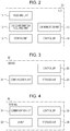
- FIG. 2 is a block diagram of a hub according this exemplary embodiment
- FIG. 3 is a block diagram of a device according to this exemplary embodiment
- FIG. 4 is a block diagram of a terminal according to this exemplary embodiment
- FIG. 5 is a flowchart illustrating a process of the hub according to this exemplary embodiment.
- FIG. 6 illustrates an example of a screen displayed in a terminal making a request for executing a function in accordance with this exemplary embodiment.
- FIG. 1 schematically illustrates the overall configuration of a device network system according to this exemplary embodiment.
- FIG. 1 shows multiple types of Internet-of-Things (IoT) devices connected to a network, such as the Internet.
- IoT Internet-of-Things
- FIG. 1 first and second multifunction devices, first and second robots, first to third devices of various types, first to fourth terminals, and first and second personal computers (PCs) are shown, and these devices are communicable with one another via hubs.
- hubs There are also devices that are directly communicable with other devices without the intervention of hubs.
- the hubs are also capable of exchanging data with each other.
- devices connectable to the Internet, including PCs (information terminals) will collectively be referred to as “IoT devices”.
- an Iot device may simply be referred to as a “device”.
- Each multifunction device is an image forming device having an image forming function (i.e., at least one of a scanning function, a printing function, a copying function, and a facsimile function).
- Each robot may be a humanoid robot as shown in FIG. 1 , or may be an animal robot or a robot of another type.
- Each of the first to third devices is, for example, a projector, a display device such as a liquid crystal display, a recording device, a playback device, an imaging device such as a camera, a clock, a monitoring camera, an automobile, a two-wheeled vehicle, an aircraft (such as an unmanned aircraft (i.e., a so-called drone)), a gaming device, or any of various types of sensing devices (such as a temperature sensor, a humidity sensor, a voltage sensor, or a current sensor).
- each of the first to third devices may be a household electrical appliance, such as a refrigerator, a rice cooker, a microwave oven, a coffee brewer, a vacuum cleaner, a washing machine, an air conditioner, or a lighting device.
- Each of the first to fourth terminals in this exemplary embodiment is assumed to be an information terminal that may be carried by a user, such as a smartphone, a tablet PC, or a portable telephone. Similar to the terminals, the first and second PCs are information terminals. The first and second PCs may be of a stationary type or a portable type. The first to fourth terminals and the first and second PCs each have an application (Iot application) installed therein for using the IoT device.
- Iot application application
- Each of the hubs is a device that relays data by connecting the above-mentioned IoT devices to a network in a wireless or wired manner.
- Each hub is equipped with an information processing device having a communication interface, at least one processor such as a central processing unit (CPU), a read-only memory (ROM), a random access memory, and a storage unit.
- the processor reads and executes a program stored in the storage unit so that various types of functions are realized.
- this exemplary embodiment relates to an example where a hub serves as an information processing device that causes a function, which will be described later, to be exhibited
- another device such as a terminal, a PC, or a device whose load is to be monitored, may serve as an information processing device that causes a function, which will be described later, to be exhibited.
- a server that manages the entire device network system according to this exemplary embodiment may be provided, and the server may cause a function, which will be described later, to be exhibited.
- FIG. 2 is a block diagram of a hub 10 according to this exemplary embodiment.
- the hub 10 has a receiving unit 11 , a device-information acquiring unit 12 , a communication unit 13 , a controller 14 , and a storage unit 15 . Components that are not used for describing this exemplary embodiment are omitted from FIG. 2 .
- the receiving unit 11 receives, from any of the devices, an execution request for a function to be provided by another device. In the course of receiving the execution request, the receiving unit 11 also presents various types of screens, such as a warning screen, to the device serving as the source of the execution request.
- the device-information acquiring unit 12 acquires information related to the device. The acquired information is stored in the storage unit 15 , where necessary.
- the communication unit 13 is a communication interface that functions as a transmitter for transmitting data to another device and also functions as a receiver for receiving data from another device.
- the communication unit 13 may be a communication interface having a wireless communication function or may be a communication interface having a wired communication function.
- the communication unit 13 is compliant with one or more types of communication methods and may communicate with a communication partner in accordance with a communication method suitable for the communication partner (i.e., a communication method that the communication partner is compliant with). Examples of the communication methods include infrared communication, visible light communication, Wi-Fi (registered trademark) communication, and short-range wireless communication (such as near field communication (NFC)).
- short-range wireless communication examples include Felica (registered trademark), Bluetooth (registered trademark), and radio frequency identifier (RFID).
- RFID radio frequency identifier
- wireless communication of another method may be used as short-range wireless communication.
- the communication unit 13 may change the communication method or the frequency band in accordance with the communication partner, or may change the communication method or the frequency band in accordance with the surrounding environment.
- the controller 14 controls the operation of each component of the hub 10 .
- the storage unit 15 is a storage device, such as a hard disk drive (HDD) or a memory (e.g., a solid state drive (SSD)), and stores various types of information.
- HDD hard disk drive
- SSD solid state drive
- the components 11 to 14 in the hub 10 are realized in accordance with cooperative operation between a computer included in the hub 10 and a program executed by the CPU.
- the program used in this exemplary embodiment may be provided by a communication unit or may be provided by being stored in a recording medium.
- the storage unit 15 is realized by the storage device, such as the HDD or the RAM, included in the hub 10 .
- FIG. 3 is a block diagram of a device 20 according to this exemplary embodiment.
- the device 20 has a communication unit 21 , a controller 22 , and a storage unit 23 .
- the communication unit 21 is a communication interface having a function for communicating with the hub 10 or another device.
- the communication unit 21 may be a communication interface having a wired communication function, or may be a communication interface having a wireless communication function.
- the communication unit 21 has a communication interface according to the specifications of the device 20 .
- the storage unit 23 has registered therein device execution information related to execution of a function requested from an information terminal, and the controller 22 controls the execution of a function included in the device 20 in accordance with the setting contents of the device execution information.
- the storage unit 23 is a storage device, such as an HDD or a memory (e.g., an SSD), and stores various types of application programs and various types of data.
- the storage unit 23 stores therein device execution information, as mentioned above.
- Device execution information has registered therein an execution condition designated by a user who desires to use a function provided by the device 20 , or at least an execution condition related to a function to be executed by the device 20 .
- an execution condition a condition related to the execution of a function is designated by the user.
- an execution condition includes execution schedule information containing a function that the user desires to execute, as well as an execution period and an execution timing of the function.
- device execution information contains data to be processed in the aforementioned function.
- the storage unit 23 may store not only currently-valid device execution information, but also past device execution information corresponding to past execution of the function as history information without deleting the past device execution information.
- FIG. 4 is a block diagram of a terminal 30 according to this exemplary embodiment.
- the terminal 30 in FIG. 4 corresponds to each of the first to fourth terminals in FIG. 1 .
- the terminal 30 belongs to the device 20 shown in FIG. 2
- the terminal 30 is shown separately from the device 20 that simply provides a function since the terminal 30 is capable of requesting the hub 10 for execution of a function for using the device 20 .
- the terminal 30 has a communication unit 31 , a user interface (UI) unit 32 , a controller 33 , and a storage unit 34 . Components that are not used for describing this exemplary embodiment are omitted from FIG. 4 .
- the communication unit 31 is a communication interface having a function for communicating with the hub 10 or another device.
- the communication unit 31 may be a communication interface having a wireless communication function, or may be a communication interface having a wired communication function.
- the communication unit 31 is compliant with one or more types of communication methods and may communicate with a communication partner in accordance with a communication method suitable for the communication partner (i.e., a communication method that the communication partner is compliant with). Examples of the communication methods include infrared communication, visible light communication, Wi-Fi communication, and short-range wireless communication.
- the communication unit 21 may change the communication method or the frequency band in accordance with the communication partner, or may change the communication method or the frequency band in accordance with the surrounding environment.
- the UI unit 32 is a user interface and includes a display unit and an operable unit.
- the display unit is a display device, such as a liquid crystal display.
- the operable unit is an input device, such as a touchscreen or a keyboard.
- the UI unit 32 may be a user interface having both a display function and an operable function (e.g., a touchscreen display or a device that electronically displays a keyboard on a display).
- the controller 33 controls the operation of each component of the terminal 30 .
- the storage unit 34 is a storage device, such as an HDD or a memory (e.g., an SSD), and stores various types of application programs and various types of data.
- FIG. 5 is a flowchart illustrating a process of the hub 10 operating in response to a function execution request from a device (terminal 30 ), and FIG. 6 illustrates an example of a screen displayed on the display unit of the terminal 30 during the operation. The following description relates to the operation according to this exemplary embodiment when a first user makes a function execution request by using the first terminal.
- the first user causes the first terminal to display a setting screen 41 by activating a predetermined application, and performs a setting process for executing a desired function via the setting screen 41 .
- the first user operates a predetermined enter button.
- the terminal 30 transmits the function execution request, including the setting contents, made by the first user to the hub 10 in accordance with the user operation.
- the terminal 30 When the receiving unit 11 in the hub 10 receives the execution request from the terminal 30 in step S 101 , the terminal 30 is caused to display a confirmation screen 42 for confirming the contents.
- the term “receives” in this case does not mean that a process to be performed based on an execution condition designated in the execution request is accepted, but means that the execution request is received (acquired).
- the user may set a function for using a single device alone, or may set a cooperative function for realizing a series of functions by causing a mailing function, a printing function, and a storage function (transport function), which are respectively provided by the second PC receiving a mail, the first multifunction device performing a printing process, and the first robot used for storing a printed material, to operate in cooperation with one another, as in “PRINT OUT RECEIPT MAIL RECEIVED BY SECOND PC AND MAKE FIRST ROBOT STORE MAIL IN CABINET” shown in FIG. 6 .
- “13:00 EVERY FRIDAY” is set as the execution period as an example, the function may be executed only once instead of being executed regularly.
- the timing for starting the function may be set to a certain timeframe by designating a range from a certain time point to another time point.
- FIG. 6 illustrates an example where the first user makes a request for starting the function at 13:00 every Friday
- another user may have already made a request for executing a function using at least one of the second PC, the first multifunction device, and the first robot in the same time period (i.e., a time period overlapping the execution period), and each device may have already received the request.
- the first user himself/herself may perhaps make a request for executing a function using at least one of the second PC, the first multifunction device, and the first robot via the first terminal or via an information terminal, such as a PC, usable by the first user, other than the first terminal.
- the amount of data handled is larger than in a case where the function is executed in response to a single execution request.
- the load on the device increases. For example, in a case where a device concurrently receives data from other multiple devices, the communication load on the device increases. If the load becomes excessive, there is a risk that the device may be unable to execute the function properly.
- the controller 14 in the hub 10 checks the load status of each device that provides the requested function (i.e., a cooperative function in this example) in step S 102 .
- the device-information acquiring unit 12 acquires, from a device that is set to execute the function designated by the user, device execution information about the device. Then, based on the execution condition designated in the execution request, that is, at 13:00 every Friday in this example, the number of execution requests corresponding to that time is checked to determine how many execution requests the device is expected to handle. It is regarded that the larger the number, the higher the load. For higher accuracy, the amount of data to be processed in the execution request may be checked instead of the number of execution requests. It is regarded that the larger the amount of data to be handled, the higher the load. Since the load status is obtainable from the device execution information acquired by the device-information acquiring unit 12 , the device execution information corresponds to load-related information. The device execution information acquired from the device may be stored in the storage unit 15 for a predetermined period. Since the same device execution information is not acquired again from the device, an increase in network load may be avoided.
- the controller 14 confirms the load on the device that executes the function. If it is determined that the device has no potential to properly execute the function as a result of the increased amount of data to be handled by the device (NO in step S 103 ), the controller 14 determines that it is difficult to provide the function requested by the user (i.e., the overall series of functions in the case of a cooperative function).
- the receiving unit 11 provides a warning notification by causing the first terminal to display a warning screen 43 under the control of the controller 14 . For example, in a case where the amount of data handled by the device determined from the device execution information exceeds a predetermined value, it is determined that the device has no potential to properly execute the function.
- the predetermined value may be determined from, for example, the specifications of the device, or the communication unit or communication method used for communication by the device.
- the first user By viewing the warning screen 43 displayed in the first terminal, the first user is notified of the possibility that the execution may be delayed or that proper execution is not possible under the execution condition set via the setting screen 41 . While being notified of the possibility that the execution may be delayed or that proper execution is not possible, the first user selects a “YES” button if the first user desires that the function still be executed under the execution condition set via the setting screen 41 . If the set function execution request is maintained regardless of the warning (YES in step S 105 ), the receiving unit 11 causes the first terminal to display a reception completion screen 44 and notifies the first user that the execution condition set via the setting screen 41 is received.
- step S 109 the controller 14 commands the corresponding device to execute the function under the execution condition set via the setting screen 41 .
- the controller 14 commands the second PC to execute the mailing function so as to transmit a mail with a receipt attached thereto to the first multifunction device.
- the controller 14 also commands the first multifunction device to execute the printing function so as to print the receipt attached to the mail upon reception of the mail from the second PC.
- the controller 14 also commands the first robot to execute the storage function (transport function) so as to transport and store the receipt printed by the first multifunction device to a cabinet. Then, the controller 14 gives a command such that the above functions are executed at 13:00 every Friday. Because the first multifunction device and the first robot each have to wait until the upstream function is completed, it is necessary to give extra time to a certain extent to the execution start timing.
- the receiving unit 11 causes the first terminal to display the reception completion screen 44 and notifies the first user that the execution condition set via the setting screen 41 is received. Then, in step S 109 , the controller 14 commands the corresponding device to execute the function under the execution condition set via the setting screen 41 .
- the controller 14 presents an execution condition under which the function is expected to be properly executable as a recommended setting. For example, similar to when the load status of the device is confirmed, the controller 14 causes the device-information acquiring unit 12 to acquire device execution information about a device that is set to execute a function designated by a user. If the device execution information is stored in the storage unit 15 , the information is used.
- an execution period in which the number of execution requests is smaller than or equal to a predetermined number or in which the amount of data to be processed is smaller than or equal to a predetermined amount is searched for.
- the predetermined number and the predetermined amount are threshold values used for determining whether a function is expected to be properly executable, and may be determined from, for example, the specifications of the device, or the communication unit or communication method used for communication by the device. Alternatively, an execution period in which a function is expected to be properly executable may be searched for by referring to past device execution information (history information).
- the device that is to execute the function may be changed.
- a recommended setting that causes the second multifunction device to execute the function in place of the first multifunction device may be planned.
- Priority levels may be set for the execution period and the changing of the device. For example, for a device having no potential for properly executing a function, an execution period in which the device is expected to properly execute the function may be searched for, and if such an execution period is not found as a result of the search, the device may considerably be changed to another device. If a device has no potential for properly executing a function, the device may preferentially be changed to another device of the same type.
- step S 106 the controller 14 plans an execution condition under which the function is expected to be properly executable, and presents the execution condition as a recommended setting.
- the receiving unit 11 causes the first terminal 1 to display a recommendation screen 45 including the recommended setting.
- the first user is notified of the recommended setting presented by the system by viewing the recommendation screen 45 . If the first user agrees with the execution of the function based on the recommended setting, the first user selects the “OK” button. Accordingly, when the receiving unit 11 is informed that the first user has agreed with the recommended setting (YES in step S 107 ), the receiving unit 11 causes the first terminal to display the reception completion screen 44 and notifies the first user that the function execution request based on the recommended setting has been received. Then, in step S 108 , the controller 14 commands the corresponding device to execute the function under the execution condition presented on the recommendation screen 45 .
- the first user selects a “RESET” button, causes the first terminal to display the setting screen 41 , and resets the function execution condition.
- the recommended setting is presented to the first user.
- the process may proceed to the setting screen 41 without presenting the recommended setting.
- the load status of a device is checked by referring to currently-valid or past device execution information.
- an indicator for determining the load status of a device is not limited to this.
- the status of a hardware resource of a device such as the usage rate of a CPU, the usage rate of a memory, or the available space in a storage unit of the device, may be taken into consideration.
- the following operation may be performed instead of immediately determining that there is no potential for properly executing a function.
- the controller 14 performs control to change at least one of the amount of data to be transmitted to the device and a transmitting unit used for transmitting the data.
- the method for changing (adjusting) the amount of data involves decimating or compressing the data to be transmitted, depending on the type of data. For example, if the data to be transmitted is a moving image, some of the frames are selectively transmitted instead of transmitting all of the frames. For example, frames are decimated every n frames (n ⁇ 2). Furthermore, if the data is not compressed yet, the data may be compressed before being transmitted. The amount of data to be transmitted is reduced in this manner so that the communication load is reduced.
- the communication unit transmitting unit
- the communication unit is switched from the wireless LAN to the wired LAN that provides relatively higher communication speed, depending on the communication standard.
- the amount of data transmittable at one time may be increased.
- a power saving configuration may be achieved by turning off the communication unit that is not to be used when it becomes unnecessary to use multiple communication units.
- the communication unit may be changed from a quality-oriented communication unit that transmits a smaller amount of data per unit time to a lower-quality communication unit that transmits a larger amount of data per unit time. If the currently-used communication method is Wi-Fi IEEE (Institute of Electrical and Electronics Engineers) 802.3a, the communication method may be changed to IEEE 802.3ac that provides relatively higher communication performance than the currently-used communication method.
- Wi-Fi IEEE Institute of Electrical and Electronics Engineers
- step S 102 Even when it is determined in step S 102 that the load on the device is excessive based on the device execution information and that there is no potential for the device to properly execute the function, if the device is expected to properly execute the function by changing the transmitting unit or the communication method, as described above, the load status of the device may be determined as non-problematic and the process may proceed to step S 104 . Moreover, after an execution request is received, if the received execution request is not properly executable due to an increase in the communication load when the function is to be actually executed, such a situation may be dealt with by changing the transmitting unit or the communication method, as described above.
- This exemplary embodiment is not limited to a case where a function provided by a single device is to be executed, as shown in FIG. 6 , and may include a case where an execution request for a cooperative function in which functions provided by multiple devices are cooperatively executed is designated.
- a cooperative function may be executed by cooperatively executing multiple functions included in a single device (e.g., the first multifunction device) or cooperatively executing multiple functions included in multiple devices (e.g., the second PC and the first multifunction device), as described above.
- a function included in a terminal device i.e., the first terminal in this exemplary embodiment
- giving an operation command may be used as a part of a cooperative function.
- a cooperative function may be a function to be executed without using a device as hardware.
- a cooperative function may be a function to be executed by causing multiple software programs installed in any of the devices to operate in cooperation with each other.
- a cooperative function may be a function to be executed by cooperatively executing a function included in a device as hardware and a function realized by a software program.
Abstract
Description
Claims (12)
Applications Claiming Priority (2)
| Application Number | Priority Date | Filing Date | Title |
|---|---|---|---|
| JP2018018074A JP7069767B2 (en) | 2018-02-05 | 2018-02-05 | Information processing equipment and programs |
| JP2018-018074 | 2018-02-05 |
Publications (2)
| Publication Number | Publication Date |
|---|---|
| US20190245983A1 US20190245983A1 (en) | 2019-08-08 |
| US10645240B2 true US10645240B2 (en) | 2020-05-05 |
Family
ID=67476114
Family Applications (1)
| Application Number | Title | Priority Date | Filing Date |
|---|---|---|---|
| US16/121,035 Active US10645240B2 (en) | 2018-02-05 | 2018-09-04 | Information processing device and non-transitory computer readable medium for providing a notification when a requested function is not properly executable |
Country Status (2)
| Country | Link |
|---|---|
| US (1) | US10645240B2 (en) |
| JP (1) | JP7069767B2 (en) |
Citations (3)
| Publication number | Priority date | Publication date | Assignee | Title |
|---|---|---|---|---|
| US20090190147A1 (en) * | 2008-01-22 | 2009-07-30 | Hiroya Uruta | Image forming apparatus, print control method, and computer-readable recording medium storing print control program |
| US20120173477A1 (en) * | 2010-12-29 | 2012-07-05 | Teradata Us, Inc. | Predictive resource management |
| US20140244836A1 (en) | 2013-02-25 | 2014-08-28 | Qualcomm Incorporated | Analytics engines for iot devices |
Family Cites Families (1)
| Publication number | Priority date | Publication date | Assignee | Title |
|---|---|---|---|---|
| JP2012242897A (en) | 2011-05-16 | 2012-12-10 | Canon Inc | Host computer, print control system, control method for print control system and program |
-
2018
- 2018-02-05 JP JP2018018074A patent/JP7069767B2/en active Active
- 2018-09-04 US US16/121,035 patent/US10645240B2/en active Active
Patent Citations (4)
| Publication number | Priority date | Publication date | Assignee | Title |
|---|---|---|---|---|
| US20090190147A1 (en) * | 2008-01-22 | 2009-07-30 | Hiroya Uruta | Image forming apparatus, print control method, and computer-readable recording medium storing print control program |
| US20120173477A1 (en) * | 2010-12-29 | 2012-07-05 | Teradata Us, Inc. | Predictive resource management |
| US20140244836A1 (en) | 2013-02-25 | 2014-08-28 | Qualcomm Incorporated | Analytics engines for iot devices |
| JP2016514398A (en) | 2013-02-25 | 2016-05-19 | クアルコム,インコーポレイテッド | Analysis engine for IoT devices |
Also Published As
| Publication number | Publication date |
|---|---|
| JP7069767B2 (en) | 2022-05-18 |
| JP2019135803A (en) | 2019-08-15 |
| US20190245983A1 (en) | 2019-08-08 |
Similar Documents
| Publication | Publication Date | Title |
|---|---|---|
| JP5562468B1 (en) | Controller, energy management system, remote control method, and program | |
| EP3000046B1 (en) | Image forming apparatus and method for controlling display of pop-up windows on connected devices | |
| US10353653B2 (en) | Information processing terminal, information processing method, and non-transitory computer-readable medium for specifying a position of a printer, measuring a distance range in plural communication modes | |
| US9389817B2 (en) | Information processing device, control method, and storage medium for determining wireless connection method to a device | |
| US8896874B2 (en) | Communication apparatus and control method thereof, communication system, and storage medium | |
| US20110256829A1 (en) | Radio communication terminal, method for controlling the same, and information storage medium | |
| US10397774B2 (en) | Information processing apparatus, control method, and program | |
| KR20170033774A (en) | Communication apparatus having direct wireless communication function and method for controlling communication apparatus | |
| EP3407178B1 (en) | Mobile terminal that performs near field wireless communication, control method for the mobile terminal, and storage medium | |
| US20220166685A1 (en) | Communication apparatus and control method for the same | |
| JP7172071B2 (en) | Information gathering device and program | |
| EP2991436A1 (en) | Method for transmitting call disconnection message of electronic apparatus and electronic apparatus thereof | |
| JP6199438B2 (en) | Remote control system | |
| US10530946B2 (en) | Information processing apparatus, control method of information processing apparatus, program, and information processing system for efficiently transmitting updated managed information to other information processing apparatuses | |
| US11074059B2 (en) | Non-transitory computer-readable recording medium storing instructions controlling operation of mobile terminal | |
| US10645240B2 (en) | Information processing device and non-transitory computer readable medium for providing a notification when a requested function is not properly executable | |
| US11025789B2 (en) | Ordering system, ordering server apparatus, and non-volatile computer readable recording medium | |
| JP6479113B2 (en) | Controller and remote control system | |
| JP7349595B2 (en) | Program, control method | |
| US10966273B2 (en) | Connection management apparatus and non-transitory computer readable medium | |
| US20230326330A1 (en) | Communication system in which remote control is performed from terminal apparatus, server apparatus, control method therefor, and storage medium | |
| US11468498B2 (en) | Ordering system, image forming apparatus, and non-volatile computer readable recording medium | |
| JP2018042189A (en) | Radio communication device, radio communication system, and radio communication setting program | |
| JP2016224534A (en) | Communication system, data communication device, control method thereof, and program |
Legal Events
| Date | Code | Title | Description |
|---|---|---|---|
| AS | Assignment |
Owner name: FUJI XEROX CO., LTD., JAPAN Free format text: ASSIGNMENT OF ASSIGNORS INTEREST;ASSIGNOR:TOKUCHI, KENGO;REEL/FRAME:046780/0114 Effective date: 20180702 |
|
| FEPP | Fee payment procedure |
Free format text: ENTITY STATUS SET TO UNDISCOUNTED (ORIGINAL EVENT CODE: BIG.); ENTITY STATUS OF PATENT OWNER: LARGE ENTITY |
|
| STPP | Information on status: patent application and granting procedure in general |
Free format text: FINAL REJECTION MAILED |
|
| STPP | Information on status: patent application and granting procedure in general |
Free format text: RESPONSE AFTER FINAL ACTION FORWARDED TO EXAMINER |
|
| STPP | Information on status: patent application and granting procedure in general |
Free format text: NOTICE OF ALLOWANCE MAILED -- APPLICATION RECEIVED IN OFFICE OF PUBLICATIONS |
|
| STCF | Information on status: patent grant |
Free format text: PATENTED CASE |
|
| AS | Assignment |
Owner name: FUJIFILM BUSINESS INNOVATION CORP., JAPAN Free format text: CHANGE OF NAME;ASSIGNOR:FUJI XEROX CO., LTD.;REEL/FRAME:058287/0056 Effective date: 20210401 |
|
| MAFP | Maintenance fee payment |
Free format text: PAYMENT OF MAINTENANCE FEE, 4TH YEAR, LARGE ENTITY (ORIGINAL EVENT CODE: M1551); ENTITY STATUS OF PATENT OWNER: LARGE ENTITY Year of fee payment: 4 |