US10637188B2 - Electrical plug connector - Google Patents
Electrical plug connector Download PDFInfo
- Publication number
- US10637188B2 US10637188B2 US16/208,607 US201816208607A US10637188B2 US 10637188 B2 US10637188 B2 US 10637188B2 US 201816208607 A US201816208607 A US 201816208607A US 10637188 B2 US10637188 B2 US 10637188B2
- Authority
- US
- United States
- Prior art keywords
- contact element
- protrusions
- sleeve
- electrical
- fixing element
- Prior art date
- Legal status (The legal status is an assumption and is not a legal conclusion. Google has not performed a legal analysis and makes no representation as to the accuracy of the status listed.)
- Active
Links
- 230000013011 mating Effects 0.000 claims abstract description 27
- 238000007789 sealing Methods 0.000 claims description 11
- 238000000034 method Methods 0.000 claims description 9
- 230000008569 process Effects 0.000 description 4
- 230000004044 response Effects 0.000 description 4
- 238000013461 design Methods 0.000 description 3
- 238000001746 injection moulding Methods 0.000 description 2
- 239000000463 material Substances 0.000 description 2
- 238000012986 modification Methods 0.000 description 2
- 230000004048 modification Effects 0.000 description 2
- 230000009471 action Effects 0.000 description 1
- 230000008901 benefit Effects 0.000 description 1
- 230000000295 complement effect Effects 0.000 description 1
- 238000011161 development Methods 0.000 description 1
- 238000005516 engineering process Methods 0.000 description 1
- 238000012546 transfer Methods 0.000 description 1
Images


Classifications
-
- H—ELECTRICITY
- H01—ELECTRIC ELEMENTS
- H01R—ELECTRICALLY-CONDUCTIVE CONNECTIONS; STRUCTURAL ASSOCIATIONS OF A PLURALITY OF MUTUALLY-INSULATED ELECTRICAL CONNECTING ELEMENTS; COUPLING DEVICES; CURRENT COLLECTORS
- H01R13/00—Details of coupling devices of the kinds covered by groups H01R12/70 or H01R24/00 - H01R33/00
- H01R13/62—Means for facilitating engagement or disengagement of coupling parts or for holding them in engagement
- H01R13/627—Snap or like fastening
-
- H—ELECTRICITY
- H01—ELECTRIC ELEMENTS
- H01R—ELECTRICALLY-CONDUCTIVE CONNECTIONS; STRUCTURAL ASSOCIATIONS OF A PLURALITY OF MUTUALLY-INSULATED ELECTRICAL CONNECTING ELEMENTS; COUPLING DEVICES; CURRENT COLLECTORS
- H01R13/00—Details of coupling devices of the kinds covered by groups H01R12/70 or H01R24/00 - H01R33/00
- H01R13/40—Securing contact members in or to a base or case; Insulating of contact members
- H01R13/42—Securing in a demountable manner
- H01R13/436—Securing a plurality of contact members by one locking piece or operation
- H01R13/4364—Insertion of locking piece from the front
- H01R13/4365—Insertion of locking piece from the front comprising a temporary and a final locking position
-
- H—ELECTRICITY
- H01—ELECTRIC ELEMENTS
- H01R—ELECTRICALLY-CONDUCTIVE CONNECTIONS; STRUCTURAL ASSOCIATIONS OF A PLURALITY OF MUTUALLY-INSULATED ELECTRICAL CONNECTING ELEMENTS; COUPLING DEVICES; CURRENT COLLECTORS
- H01R13/00—Details of coupling devices of the kinds covered by groups H01R12/70 or H01R24/00 - H01R33/00
- H01R13/40—Securing contact members in or to a base or case; Insulating of contact members
- H01R13/42—Securing in a demountable manner
- H01R13/424—Securing in base or case composed of a plurality of insulating parts having at least one resilient insulating part
-
- H—ELECTRICITY
- H01—ELECTRIC ELEMENTS
- H01R—ELECTRICALLY-CONDUCTIVE CONNECTIONS; STRUCTURAL ASSOCIATIONS OF A PLURALITY OF MUTUALLY-INSULATED ELECTRICAL CONNECTING ELEMENTS; COUPLING DEVICES; CURRENT COLLECTORS
- H01R13/00—Details of coupling devices of the kinds covered by groups H01R12/70 or H01R24/00 - H01R33/00
- H01R13/40—Securing contact members in or to a base or case; Insulating of contact members
- H01R13/42—Securing in a demountable manner
- H01R13/426—Securing by a separate resilient retaining piece supported by base or case, e.g. collar or metal contact-retention clip
-
- H—ELECTRICITY
- H01—ELECTRIC ELEMENTS
- H01R—ELECTRICALLY-CONDUCTIVE CONNECTIONS; STRUCTURAL ASSOCIATIONS OF A PLURALITY OF MUTUALLY-INSULATED ELECTRICAL CONNECTING ELEMENTS; COUPLING DEVICES; CURRENT COLLECTORS
- H01R13/00—Details of coupling devices of the kinds covered by groups H01R12/70 or H01R24/00 - H01R33/00
- H01R13/46—Bases; Cases
- H01R13/52—Dustproof, splashproof, drip-proof, waterproof, or flameproof cases
- H01R13/5202—Sealing means between parts of housing or between housing part and a wall, e.g. sealing rings
-
- H—ELECTRICITY
- H01—ELECTRIC ELEMENTS
- H01R—ELECTRICALLY-CONDUCTIVE CONNECTIONS; STRUCTURAL ASSOCIATIONS OF A PLURALITY OF MUTUALLY-INSULATED ELECTRICAL CONNECTING ELEMENTS; COUPLING DEVICES; CURRENT COLLECTORS
- H01R13/00—Details of coupling devices of the kinds covered by groups H01R12/70 or H01R24/00 - H01R33/00
- H01R13/62—Means for facilitating engagement or disengagement of coupling parts or for holding them in engagement
- H01R13/639—Additional means for holding or locking coupling parts together, after engagement, e.g. separate keylock, retainer strap
-
- H—ELECTRICITY
- H01—ELECTRIC ELEMENTS
- H01R—ELECTRICALLY-CONDUCTIVE CONNECTIONS; STRUCTURAL ASSOCIATIONS OF A PLURALITY OF MUTUALLY-INSULATED ELECTRICAL CONNECTING ELEMENTS; COUPLING DEVICES; CURRENT COLLECTORS
- H01R43/00—Apparatus or processes specially adapted for manufacturing, assembling, maintaining, or repairing of line connectors or current collectors or for joining electric conductors
- H01R43/26—Apparatus or processes specially adapted for manufacturing, assembling, maintaining, or repairing of line connectors or current collectors or for joining electric conductors for engaging or disengaging the two parts of a coupling device
-
- H—ELECTRICITY
- H01—ELECTRIC ELEMENTS
- H01R—ELECTRICALLY-CONDUCTIVE CONNECTIONS; STRUCTURAL ASSOCIATIONS OF A PLURALITY OF MUTUALLY-INSULATED ELECTRICAL CONNECTING ELEMENTS; COUPLING DEVICES; CURRENT COLLECTORS
- H01R13/00—Details of coupling devices of the kinds covered by groups H01R12/70 or H01R24/00 - H01R33/00
- H01R13/46—Bases; Cases
- H01R13/52—Dustproof, splashproof, drip-proof, waterproof, or flameproof cases
- H01R13/5219—Sealing means between coupling parts, e.g. interfacial seal
-
- H—ELECTRICITY
- H01—ELECTRIC ELEMENTS
- H01R—ELECTRICALLY-CONDUCTIVE CONNECTIONS; STRUCTURAL ASSOCIATIONS OF A PLURALITY OF MUTUALLY-INSULATED ELECTRICAL CONNECTING ELEMENTS; COUPLING DEVICES; CURRENT COLLECTORS
- H01R2201/00—Connectors or connections adapted for particular applications
- H01R2201/26—Connectors or connections adapted for particular applications for vehicles
Definitions
- the invention relates to an electrical plug connector and a method for fitting the electrical plug connector to a mating connector.
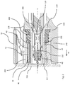
- FIG. 1 is a cross-section view of an electrical plug connector in accordance with an embodiment of the invention
- FIG. 2 is a cross-section view of the electrical plug connector in the fitted state in accordance with an embodiment of the invention
- FIGS. 3 a and 3 b are perspective views of a the plug housing of the electrical plug connector counter to the insert direction in accordance with an embodiment of the invention
- FIG. 4 is a cross-section view of the electrical plug connector in the fitted state in accordance with an embodiment of the invention.
- FIG. 5 is a perspective view of the fixing element in accordance with an embodiment of the invention.
- FIG. 6 is a cross-section view of the fixing element perpendicular to the longitudinal axis in accordance with an embodiment of the invention.
- FIG. 7 is an exploded view of the electrical plug connector and the mating plug housing in accordance with an embodiment of the invention.
- An electrical plug connector contains a plug housing having a wall which defines a first opening.
- a sleeve-like contact element holder surrounds the first opening along a longitudinal axis in a plug-in direction.
- the contact element holder is designed for receiving and holding an electrical contact element.
- a collar extends from the wall in the plug-in direction along the longitudinal axis and surrounds the contact element holder at a distance.
- a sleeve-like fixing element is attached releasably to the contact element holder.
- the fixing element surrounds the contact element holder radially.
- the fixing element surrounds at least a part of the contact element holder along the longitudinal axis.
- a plurality of first protrusions project from an outer surface of the fixing element into a free space between the fixing element and the collar.
- a plurality of second protrusions project from an inner surface of the fixing element through a plurality of second openings into the contact element holder.
- the first protrusions and the second protrusions are designed so that, after fitting the plug housing together with a mating plug housing, a counter collar of the mating plug housing extends into the free space and is in engagement with the first protrusions. This causes the first protrusions to be pressed inwardly and the second protrusions to be pressed inwardly.
- the second protrusions are also pressed against an electrical contact element that is held in the contact element holder.
- a fixing element which, when the electrical plug connector is not inserted, is attached loosely around the contact element holder so that when mounting the electrical contact element, no problems occur through obstructions which project into the contact chamber, and thus mounting the contact can be carried out with comparatively little force.
- the inside of the contact chamber is slightly larger than the external dimensions of the electrical contact element so that the electrical contact element has a small amount of play in the contact chamber and can be easily inserted therein as a result.
- the fixing element is flexible in design so that mounting the electrical contact element can be carried out in each case with little force although the clearance between the protruding elements already has the same size as the external dimensions of the contact element.
- the collar of the mating connector deforms the fixing element so that protrusions which are attached to the fixing element project into the contact chamber and press against the contact element.
- the play exhibited by the contact element in the contact chamber is thereby eliminated.
- the contact element is now, even in the case of severe vibrations, held firmly fixed between the protrusions. The wear or damage caused by vibrations is thus minimized.
- the contact element holder preferably comprises a sleeve-like fixing element and the collar preferably has a circular or oval cross-section.
- a circular or oval structure requires comparatively simple injection moulding tools. Sliding on the fixing element is particularly simple with this cross-section.
- the collar of the mating connector likewise has a circular or oval cross-section so that, after fitting together, the parts lie concentrically around the electrical contact element. This structural shape enables the development of compact electrical plug connector systems.
- the inner diameter of the fixing element is particularly preferably larger than the outer diameter of the contact element holder and the outer diameter of the fixing element is smaller than the inner diameter of the collar.
- the fixing element is preferably flexibly deformable in the radial direction in relation to the longitudinal axis. Through the flexible deformability the protrusions can be moved flexibly in the direction of the contact element and vice versa. The electrical plug connector can thereby be fitted and released many times without the fixing element losing its function.
- the wall thickness of the fixing element varies along the periphery of the fixing element.
- the fixing element consists of plastic and is made in an injection moulding process. Areas with a reduced wall thickness are less resistant to deformation and can be deformed flexibly up to a certain degree. Through the deliberate distribution of areas with increased wall thickness and reduced wall thickness it is possible to adjust the flexibility of the fixing element, more particularly in the radial direction.
- the areas of the fixing element from which first protrusions and/or second protrusions originate preferably have a greater wall thickness.
- a greater wall thickness makes the areas of the fixing element more rigid and more inflexible.
- the areas where the protrusions are attached have to transfer forces and therefore have to be more rigid.
- one first protrusion and one second protrusion preferably extend counter to one another and at right angles to the outer surface of the fixing element, along a common axis, away from one another.
- first protrusions and the second protrusions are arranged uniformly along the periphery of the fixing element. Through this arrangement of the protrusions the fixing element is deformed evenly along the periphery and the electrical contact element is supported evenly along its periphery.
- the first protrusions are preferably smaller than the second protrusions.
- the first protrusions should project as little as possible into the free space in order not to unnecessarily increase the structural size of the electrical plug connection and not impair the seal in its sealing function.
- the first protrusions can be designed in all conceivable forms, for example, as bulges or ribs.
- the size of the protrusions which extend radially from the surface of the fixing element corresponds roughly to the play of the electrical contact element in the contact element chamber.
- the contact element holder preferably has a contact element chamber for holding the electrical contact element, wherein the inside of the contact element chamber is free of second protrusions.
- the electrical contact element during the process of fitting together with the mating plug, can furthermore be aligned in relation to a complementary electrical contact element at least at the start of the process. Small tolerances of the electrical plug connector can thereby be compensated. As soon as the counter collar comes into engagement with the first protrusions and thereby presses the second protrusions against the electrical contact element, the electrical contact element can no longer be moved.
- the second protrusions are designed in the manner of ribs and the second openings are designed in the manner of slits wherein the slits extend from the free end of the contact element holder counter to the plug-in direction.
- An electrical contact element is preferably held in the contact element holder wherein the electrical contact element has a rectangular cross-section and wherein the contact element holder is designed to hold the electrical contact element in relation to the longitudinal axis with restricted rotation relative to the longitudinal axis.
- the design of the electrical contact element with a box-like structure is widespread in technology when the mating plug connector is fitted with flat blades. In order to fix this design of the electrical contact element only four protrusions are required.
- the electrical contact element preferably has four side faces wherein each side face of the electrical contact element is arranged in each case opposite a second protrusion of the fixing element. With the arrangement of the protrusions opposite the side faces it is ensured that the retaining force acts directly on the side face. In practice protrusions and side faces are arranged so that they are at right angles to one another.
- a ring-shaped sealing element which surrounds the contact element holder is arranged between the wall and the fixing element wherein the fixing element holds the ring-shaped sealing element in position.
- the fixing element holds a ring-shaped sealing element in position by its end opposite the plug-in direction. The fixing element thus serves as a safeguard against losing the ring-shaped sealing element during transport. It is particularly preferred if the outer diameter of the fixing element is slightly smaller than the outer diameter of the sealing element in order not to impair the sealing action thereof.
- the fixing element preferably has retaining arms which interact with retaining openings in the contact element holder in order to hold the fixing element on the contact element holder.
- a particularly simple manner of fastening the fixing element on the contact element holder uses retaining arms which are introduced with retaining openings in the contact element holder. It is however also conceivable to reverse the position of the arms and openings. In principle all conceivable snap-fitting or detent connections can be used where technically possible.
- a process for fitting together an electrical plug connector and an electrical mating connector is particularly preferred.
- the process comprises the following method steps:
- FIG. 1 shows an electrical plug connector 10 in a sectional view.
- the electrical plug connector 10 comprises a plug housing 100 and a wall 110 which has a first opening 120 .
- a sleeve-like contact element holder 130 designed for receiving and holding an electrical contact element 300 , extends in the plug-in direction M from the wall 110 , surrounding the first opening 120 , along a longitudinal axis X.
- a collar 140 extends in the plug-in direction M from the wall 110 , surrounding the contact element holder 130 at a distance 142 , along the longitudinal axis X.
- a sleeve-like fixing element 40 is detachably attached to the contact element holder 130 . The fixing element 40 radially encloses the contact element holder 130 .
- the fixing element 40 at least along a portion of the contact element holder 130 surrounds the contact element holder 130 along the longitudinal axis X.
- a plurality of first protrusions 44 project from an outer surface 42 of the fixing element 40 into a free space 150 between the fixing element 40 and the collar 140 .
- a plurality of second protrusions 48 project from an inner surface 46 of the fixing element 40 through a plurality of second openings 132 into the contact element holder 130 .
- FIG. 2 shows an electrical plug connector of the invention in a sectional view in the fitted state.
- the first protrusions 44 and the second protrusions 48 are designed in such a way that after fitting the plug housing 100 together with the mating plug housing 200 a counter collar 240 of the mating plug housing 200 extends into the free space 150 and engages there with the first protrusions 44 whereby the first protrusions 44 are pressed inwards and whereby the second protrusions 48 are pressed inwards.
- the second protrusions 48 are thereby pressed against an electrical contact element 300 held in the contact element holder 130 .
- a ring-shaped sealing element 400 surrounding the contact element holder 130 , is arranged between the wall 110 and the fixing element 40 .
- the fixing element 40 has retaining arms 50 which interact with retaining openings 138 in the contact element holder 130 in order to hold the fixing element 40 on the contact element holder 130 .
- FIG. 3 a shows the plug housing 100 of the electrical plug connector of the invention in a perspective view, counter to the plug-in direction.
- the contact element holder 130 and the collar 140 have a circular or oval cross-section.
- the contact element holder 130 has a contact element chamber 134 for holding the electrical contact element 300 .
- the contact element holder 130 furthermore has retaining openings 138 as well as slit-like second openings 132 , divided into vertical openings 132 a and horizontal openings 132 b.
- FIG. 3 b shows the plug housing of the electrical plug connector of the invention in a perspective view counter to the plug-in direction.
- the fixing element 40 has an oval cross-section.
- the inside of the contact element chamber 134 is free of second protrusions 48 when the electrical plug connector is not fitted together with the mating plug connector.
- the electrical contact element 300 is thus in contact with the second protrusions 48 but is not restricted in movement.
- FIG. 4 shows a sectional view of the electrical plug-in connector of the invention in the fitted state, wherein the section runs transversely to the longitudinal axis.
- the internal diameter of the fixing element 40 is greater than the external diameter of the contact element holder 130 .
- the external diameter of the fixing element 40 is smaller than the internal diameter of the collar 140 .
- the second protrusions 48 are designed as ribs and divided into vertical protrusions 48 a and horizontal protrusions 48 b .
- the second openings 132 are designed as slits and are divided into vertical openings 132 a and horizontal openings 132 b .
- the vertical protrusions 48 a and the horizontal protrusions 48 b are placed in their corresponding vertical openings 132 a and horizontal openings 132 b respectively.
- the slits 136 extend from the free end 137 of the contact element holder 130 counter to the plug-in direction M.
- An electrical contact element 300 is held in the contact element holder 130 .
- the electrical contact element 300 has a rectangular cross-section.
- the contact element holder 130 is designed to hold the electrical contact element 300 restricted in its freedom of movement in relation to the longitudinal axis X.
- the electrical contact element 300 has four side faces 302 wherein each side face 302 of the electrical contact element 300 is arranged respectively opposite a second protrusion 48 of the fixing element 40 .
- FIGS. 5 and 6 show details of the fixing element 40 wherein the section in FIG. 6 runs transversely to the longitudinal axis.
- the wall thickness of the fixing element 40 varies along the periphery of the fixing element 40 .
- the areas of the fixing element 40 from which first protrusions 44 and/or second protrusions 48 originate have a greater wall thickness.
- one first protrusion 44 and one second protrusion 48 extend counter to one another and away from one another at right angles to the outer surface 42 of the fixing element 40 along a common axis A.
- the first protrusions 44 and the second protrusions 48 are arranged uniformly along the periphery of the fixing element 40 .
- the first protrusions 44 are smaller than the second protrusions 48 .
- FIG. 7 shows, in an exploded view, the electrical plug connector 10 comprising the plug housing 100 , the ring-shaped sealing element 400 and the fixing element 40 , as well as the mating plug housing 200 with counter collars 240 .
- An electric lead 500 projects out from the plug housing 100 .
- one or more includes a function being performed by one element, a function being performed by more than one element, e.g., in a distributed fashion, several functions being performed by one element, several functions being performed by several elements, or any combination of the above.
- first, second, etc. are, in some instances, used herein to describe various elements, these elements should not be limited by these terms. These terms are only used to distinguish one element from another.
- a first contact could be termed a second contact, and, similarly, a second contact could be termed a first contact, without departing from the scope of the various described embodiments.
- the first contact and the second contact are both contacts, but they are not the same contact.
- the term “if” is, optionally, construed to mean “when” or “upon” or “in response to determining” or “in response to detecting,” depending on the context.
- the phrase “if it is determined” or “if [a stated condition or event] is detected” is, optionally, construed to mean “upon determining” or “in response to determining” or “upon detecting [the stated condition or event]” or “in response to detecting [the stated condition or event],” depending on the context.
Abstract
Description
-
- providing an electrical plug connector and an electrical mating connector;
- moving the electrical plug connector along a longitudinal axis in a plug-in direction to the electrical mating connector;
- introducing a counter collar of a mating plug housing of the mating connector of the electrical plug connector;
- moving inwards first protrusions, projecting into the free space, with the counter collar;
- deforming a sleeve-like fixing element through the first protrusions attached to the fixing element;
- moving inwards second protrusions which are attached on the fixing element so that the second protrusions project into the inside of a contact element holder;
- clamping an electrical contact element, which is held in the contact element holder, with the second protrusions.
Claims (18)
Applications Claiming Priority (3)
| Application Number | Priority Date | Filing Date | Title |
|---|---|---|---|
| EP17205961.0A EP3496210B1 (en) | 2017-12-07 | 2017-12-07 | Electric plug connector |
| EP17205961 | 2017-12-07 | ||
| EP17205961.0 | 2017-12-07 |
Publications (2)
| Publication Number | Publication Date |
|---|---|
| US20190181585A1 US20190181585A1 (en) | 2019-06-13 |
| US10637188B2 true US10637188B2 (en) | 2020-04-28 |
Family
ID=60627571
Family Applications (1)
| Application Number | Title | Priority Date | Filing Date |
|---|---|---|---|
| US16/208,607 Active US10637188B2 (en) | 2017-12-07 | 2018-12-04 | Electrical plug connector |
Country Status (3)
| Country | Link |
|---|---|
| US (1) | US10637188B2 (en) |
| EP (1) | EP3496210B1 (en) |
| CN (1) | CN109980403B (en) |
Cited By (2)
| Publication number | Priority date | Publication date | Assignee | Title |
|---|---|---|---|---|
| US11171440B2 (en) * | 2019-03-20 | 2021-11-09 | Aptiv Technologies Limited | Backing plate for mounting and sealing an electrical connector to an intermediate surface |
| US20220311174A1 (en) * | 2020-03-27 | 2022-09-29 | Aptiv Technologies Limited | Sealed electrical connector |
Families Citing this family (2)
| Publication number | Priority date | Publication date | Assignee | Title |
|---|---|---|---|---|
| JP7410073B2 (en) | 2021-03-24 | 2024-01-09 | 矢崎総業株式会社 | connector unit |
| CN216903471U (en) * | 2022-02-16 | 2022-07-05 | 宁德时代新能源科技股份有限公司 | Connector, battery and power consumption device |
Citations (16)
| Publication number | Priority date | Publication date | Assignee | Title |
|---|---|---|---|---|
| US5389014A (en) * | 1992-08-11 | 1995-02-14 | The Whitaker Corporation | Electrical connector having secondary locking mechanism |
| US6083057A (en) * | 1997-08-14 | 2000-07-04 | Amphenol-Tuchel Electronics Gmbh | Electric connector |
| US6123574A (en) * | 1997-07-29 | 2000-09-26 | Sumitomo Wiring Systems, Ltd. | Female connector |
| US6186813B1 (en) * | 1996-02-23 | 2001-02-13 | Yazaki Corporation | Double retaining connector |
| EP1235306A2 (en) | 2001-02-27 | 2002-08-28 | Yazaki Corporation | Electrical connector |
| US6537108B2 (en) * | 2000-09-27 | 2003-03-25 | Yazaki Corporation | Retaining structure of front holder to connector housing |
| US6913494B2 (en) * | 2002-07-17 | 2005-07-05 | Tyco Electronics Corporation | Electrical connector apparatus, methods and articles of manufacture |
| US20100055961A1 (en) | 2008-08-29 | 2010-03-04 | Tyco Electronics Corporation | Terminal position assurance member for electrical connector |
| US8231409B2 (en) * | 2007-02-26 | 2012-07-31 | Fci Automotive Holding | Connector having a front grid actuated by a counterpart connector |
| WO2013013967A1 (en) | 2011-07-08 | 2013-01-31 | Fci Automotive Holding | Connector and connector assembly |
| US8974243B2 (en) * | 2012-02-16 | 2015-03-10 | Md Elektronik Gmbh | Cable for transmitting signals |
| US8979599B2 (en) * | 2010-09-24 | 2015-03-17 | Tbi | Connector having insertion detection |
| US9017111B2 (en) * | 2012-04-26 | 2015-04-28 | Sumitomo Wiring Systems, Ltd. | Connector with a locking lance |
| US20160197440A1 (en) | 2013-07-16 | 2016-07-07 | Sumitomo Wiring Systems, Ltd. | Connector |
| EP3252876A1 (en) | 2016-06-01 | 2017-12-06 | Delphi Technologies, Inc. | Electrical connector with encoding function |
| EP3252875A1 (en) | 2016-06-02 | 2017-12-06 | Delphi International Operations Luxembourg S.à r.l. | Electrical connector assembly |
Family Cites Families (3)
| Publication number | Priority date | Publication date | Assignee | Title |
|---|---|---|---|---|
| BRPI0105829B1 (en) * | 2000-11-17 | 2016-05-24 | Framatome Connectors Int | plug connector |
| US7467958B2 (en) * | 2007-03-22 | 2008-12-23 | Tyco Electronics Corporation | Electrical connector having lever with protective shroud |
| JP5050820B2 (en) * | 2007-12-05 | 2012-10-17 | 住友電装株式会社 | connector |
-
2017
- 2017-12-07 EP EP17205961.0A patent/EP3496210B1/en active Active
-
2018
- 2018-12-04 US US16/208,607 patent/US10637188B2/en active Active
- 2018-12-05 CN CN201811478603.7A patent/CN109980403B/en active Active
Patent Citations (17)
| Publication number | Priority date | Publication date | Assignee | Title |
|---|---|---|---|---|
| US5389014A (en) * | 1992-08-11 | 1995-02-14 | The Whitaker Corporation | Electrical connector having secondary locking mechanism |
| US6186813B1 (en) * | 1996-02-23 | 2001-02-13 | Yazaki Corporation | Double retaining connector |
| US6123574A (en) * | 1997-07-29 | 2000-09-26 | Sumitomo Wiring Systems, Ltd. | Female connector |
| US6083057A (en) * | 1997-08-14 | 2000-07-04 | Amphenol-Tuchel Electronics Gmbh | Electric connector |
| US6537108B2 (en) * | 2000-09-27 | 2003-03-25 | Yazaki Corporation | Retaining structure of front holder to connector housing |
| EP1235306A2 (en) | 2001-02-27 | 2002-08-28 | Yazaki Corporation | Electrical connector |
| US6913494B2 (en) * | 2002-07-17 | 2005-07-05 | Tyco Electronics Corporation | Electrical connector apparatus, methods and articles of manufacture |
| US8231409B2 (en) * | 2007-02-26 | 2012-07-31 | Fci Automotive Holding | Connector having a front grid actuated by a counterpart connector |
| US20100055961A1 (en) | 2008-08-29 | 2010-03-04 | Tyco Electronics Corporation | Terminal position assurance member for electrical connector |
| US8979599B2 (en) * | 2010-09-24 | 2015-03-17 | Tbi | Connector having insertion detection |
| WO2013013967A1 (en) | 2011-07-08 | 2013-01-31 | Fci Automotive Holding | Connector and connector assembly |
| US8974243B2 (en) * | 2012-02-16 | 2015-03-10 | Md Elektronik Gmbh | Cable for transmitting signals |
| US9017111B2 (en) * | 2012-04-26 | 2015-04-28 | Sumitomo Wiring Systems, Ltd. | Connector with a locking lance |
| US20160197440A1 (en) | 2013-07-16 | 2016-07-07 | Sumitomo Wiring Systems, Ltd. | Connector |
| US9640905B2 (en) * | 2013-07-16 | 2017-05-02 | Sumitomo Wiring Systems, Ltd. | Connector |
| EP3252876A1 (en) | 2016-06-01 | 2017-12-06 | Delphi Technologies, Inc. | Electrical connector with encoding function |
| EP3252875A1 (en) | 2016-06-02 | 2017-12-06 | Delphi International Operations Luxembourg S.à r.l. | Electrical connector assembly |
Cited By (5)
| Publication number | Priority date | Publication date | Assignee | Title |
|---|---|---|---|---|
| US11171440B2 (en) * | 2019-03-20 | 2021-11-09 | Aptiv Technologies Limited | Backing plate for mounting and sealing an electrical connector to an intermediate surface |
| US20220037829A1 (en) * | 2019-03-20 | 2022-02-03 | Aptiv Technologies Limited | Backing plate for mounting and sealing an electrical connector to an intermediate surface |
| US11870178B2 (en) * | 2019-03-20 | 2024-01-09 | Aptiv Technologies AG | Backing plate for mounting and sealing an electrical connector to an intermediate surface |
| US20220311174A1 (en) * | 2020-03-27 | 2022-09-29 | Aptiv Technologies Limited | Sealed electrical connector |
| US11652314B2 (en) * | 2020-03-27 | 2023-05-16 | Aptiv Technologies Limited | Sealed electrical connector |
Also Published As
| Publication number | Publication date |
|---|---|
| EP3496210B1 (en) | 2023-03-01 |
| EP3496210A1 (en) | 2019-06-12 |
| CN109980403B (en) | 2021-05-28 |
| CN109980403A (en) | 2019-07-05 |
| US20190181585A1 (en) | 2019-06-13 |
Similar Documents
| Publication | Publication Date | Title |
|---|---|---|
| US10637188B2 (en) | Electrical plug connector | |
| US10788068B2 (en) | Pin and grommet fastener accommodating two directional offset and related methods | |
| US8779304B2 (en) | Device for fixing a cable to a cable outlet socket | |
| US7364472B2 (en) | Connector | |
| CN109751301B (en) | Connector with improved assembly process | |
| CN113906224B (en) | Fastening device with damping effect and component connecting structure with same | |
| JPH07151278A (en) | Joint for corrugated pipe | |
| CN112821006A (en) | Pressure relief device | |
| WO2017077408A1 (en) | Connector assembly for fiber optic cables having absorption of inner stresses and inner sealing for mounting in a fiber optic connection box | |
| US20190157800A1 (en) | Enclosure for a connector on a cable | |
| US10777339B2 (en) | Grommet, electronic member and method of forming said grommet | |
| US20160123511A1 (en) | Duct assembly with a connector | |
| US20110089680A1 (en) | Insertion Coupling | |
| CN111247698B (en) | Contact device | |
| WO2021175028A1 (en) | Nut seat structure of electronic expansion valve and mounting method therefor | |
| US6957988B2 (en) | Clip unit for holding contact | |
| JP6449270B2 (en) | Magnet carrier assembly and method for assembling magnet carrier assembly to shaft | |
| US10734862B2 (en) | Connecting system for plug positioning | |
| KR20220053018A (en) | Quick connector and connection assembly with improved sealing-ring lock | |
| GB2322441A (en) | Luminaires | |
| US11193500B2 (en) | Blower device | |
| US20170005439A1 (en) | Electrical connector with electromagnetic shielding and removable foolproofing system | |
| KR200145653Y1 (en) | Grommet | |
| KR102654321B1 (en) | Cable sealing plug for sealing a cable opening of an electric connector with a compression seal | |
| EP3430303B1 (en) | Connector system comprising a connector fitting for a fluid hose in a vehicle |
Legal Events
| Date | Code | Title | Description |
|---|---|---|---|
| FEPP | Fee payment procedure |
Free format text: ENTITY STATUS SET TO UNDISCOUNTED (ORIGINAL EVENT CODE: BIG.); ENTITY STATUS OF PATENT OWNER: LARGE ENTITY |
|
| AS | Assignment |
Owner name: APTIV TECHNOLOGIES LIMITED, BARBADOS Free format text: ASSIGNMENT OF ASSIGNORS INTEREST;ASSIGNOR:SCHMIDT, RAINER;REEL/FRAME:047969/0191 Effective date: 20181204 |
|
| STPP | Information on status: patent application and granting procedure in general |
Free format text: DOCKETED NEW CASE - READY FOR EXAMINATION |
|
| STPP | Information on status: patent application and granting procedure in general |
Free format text: NON FINAL ACTION MAILED |
|
| STPP | Information on status: patent application and granting procedure in general |
Free format text: NOTICE OF ALLOWANCE MAILED -- APPLICATION RECEIVED IN OFFICE OF PUBLICATIONS |
|
| STCF | Information on status: patent grant |
Free format text: PATENTED CASE |
|
| MAFP | Maintenance fee payment |
Free format text: PAYMENT OF MAINTENANCE FEE, 4TH YEAR, LARGE ENTITY (ORIGINAL EVENT CODE: M1551); ENTITY STATUS OF PATENT OWNER: LARGE ENTITY Year of fee payment: 4 |
|
| AS | Assignment |
Owner name: APTIV TECHNOLOGIES (2) S.A R.L., LUXEMBOURG Free format text: ENTITY CONVERSION;ASSIGNOR:APTIV TECHNOLOGIES LIMITED;REEL/FRAME:066746/0001 Effective date: 20230818 Owner name: APTIV MANUFACTURING MANAGEMENT SERVICES S.A R.L., LUXEMBOURG Free format text: MERGER;ASSIGNOR:APTIV TECHNOLOGIES (2) S.A R.L.;REEL/FRAME:066566/0173 Effective date: 20231005 Owner name: APTIV TECHNOLOGIES AG, SWITZERLAND Free format text: ASSIGNMENT OF ASSIGNORS INTEREST;ASSIGNOR:APTIV MANUFACTURING MANAGEMENT SERVICES S.A R.L.;REEL/FRAME:066551/0219 Effective date: 20231006 |