US10637070B2 - Highly porous anode catalyst layer structures for fuel flexible solid oxide fuel cells - Google Patents
Highly porous anode catalyst layer structures for fuel flexible solid oxide fuel cells Download PDFInfo
- Publication number
- US10637070B2 US10637070B2 US15/882,376 US201815882376A US10637070B2 US 10637070 B2 US10637070 B2 US 10637070B2 US 201815882376 A US201815882376 A US 201815882376A US 10637070 B2 US10637070 B2 US 10637070B2
- Authority
- US
- United States
- Prior art keywords
- anode
- ysz
- solid oxide
- core
- oxide fuel
- Prior art date
- Legal status (The legal status is an assumption and is not a legal conclusion. Google has not performed a legal analysis and makes no representation as to the accuracy of the status listed.)
- Active, expires
Links
- 239000003054 catalyst Substances 0.000 claims abstract description 48
- 239000000446 fuel Substances 0.000 claims abstract description 23
- 239000007787 solid Substances 0.000 claims abstract description 23
- 239000011258 core-shell material Substances 0.000 claims abstract description 22
- PXHVJJICTQNCMI-UHFFFAOYSA-N Nickel Chemical compound [Ni] PXHVJJICTQNCMI-UHFFFAOYSA-N 0.000 claims description 63
- 239000000463 material Substances 0.000 claims description 61
- 229910001233 yttria-stabilized zirconia Inorganic materials 0.000 claims description 31
- 239000011248 coating agent Substances 0.000 claims description 25
- 238000000576 coating method Methods 0.000 claims description 25
- 229910002845 Pt–Ni Inorganic materials 0.000 claims description 20
- 229910052759 nickel Inorganic materials 0.000 claims description 17
- 239000007784 solid electrolyte Substances 0.000 claims description 15
- 229910045601 alloy Inorganic materials 0.000 claims description 14
- 239000000956 alloy Substances 0.000 claims description 14
- 229910052763 palladium Inorganic materials 0.000 claims description 11
- 229910052697 platinum Inorganic materials 0.000 claims description 10
- 239000011148 porous material Substances 0.000 claims description 10
- 229910052737 gold Inorganic materials 0.000 claims description 7
- 239000010410 layer Substances 0.000 description 70
- 239000002245 particle Substances 0.000 description 25
- 238000010586 diagram Methods 0.000 description 20
- 239000003792 electrolyte Substances 0.000 description 16
- BASFCYQUMIYNBI-UHFFFAOYSA-N platinum Substances [Pt] BASFCYQUMIYNBI-UHFFFAOYSA-N 0.000 description 14
- 239000000203 mixture Substances 0.000 description 11
- KDLHZDBZIXYQEI-UHFFFAOYSA-N palladium Substances [Pd] KDLHZDBZIXYQEI-UHFFFAOYSA-N 0.000 description 11
- 229910002119 nickel–yttria stabilized zirconia Inorganic materials 0.000 description 10
- XEEYBQQBJWHFJM-UHFFFAOYSA-N Iron Chemical compound [Fe] XEEYBQQBJWHFJM-UHFFFAOYSA-N 0.000 description 7
- 229910052751 metal Inorganic materials 0.000 description 7
- 239000002184 metal Substances 0.000 description 7
- 239000000919 ceramic Substances 0.000 description 6
- 239000010944 silver (metal) Substances 0.000 description 6
- 229910000831 Steel Inorganic materials 0.000 description 5
- 239000010931 gold Substances 0.000 description 5
- 239000010959 steel Substances 0.000 description 5
- 239000011149 active material Substances 0.000 description 4
- 230000015572 biosynthetic process Effects 0.000 description 4
- 239000011195 cermet Substances 0.000 description 4
- 239000007789 gas Substances 0.000 description 4
- 229910001220 stainless steel Inorganic materials 0.000 description 4
- LFQSCWFLJHTTHZ-UHFFFAOYSA-N Ethanol Chemical compound CCO LFQSCWFLJHTTHZ-UHFFFAOYSA-N 0.000 description 3
- OKKJLVBELUTLKV-UHFFFAOYSA-N Methanol Chemical compound OC OKKJLVBELUTLKV-UHFFFAOYSA-N 0.000 description 3
- RTAQQCXQSZGOHL-UHFFFAOYSA-N Titanium Chemical compound [Ti] RTAQQCXQSZGOHL-UHFFFAOYSA-N 0.000 description 3
- 238000000231 atomic layer deposition Methods 0.000 description 3
- 229910017052 cobalt Inorganic materials 0.000 description 3
- 239000010941 cobalt Substances 0.000 description 3
- GUTLYIVDDKVIGB-UHFFFAOYSA-N cobalt atom Chemical compound [Co] GUTLYIVDDKVIGB-UHFFFAOYSA-N 0.000 description 3
- 239000002019 doping agent Substances 0.000 description 3
- 230000005611 electricity Effects 0.000 description 3
- -1 for example Substances 0.000 description 3
- 229910021526 gadolinium-doped ceria Inorganic materials 0.000 description 3
- 239000010936 titanium Substances 0.000 description 3
- 229910052719 titanium Inorganic materials 0.000 description 3
- OYPRJOBELJOOCE-UHFFFAOYSA-N Calcium Chemical compound [Ca] OYPRJOBELJOOCE-UHFFFAOYSA-N 0.000 description 2
- RYGMFSIKBFXOCR-UHFFFAOYSA-N Copper Chemical compound [Cu] RYGMFSIKBFXOCR-UHFFFAOYSA-N 0.000 description 2
- LCGLNKUTAGEVQW-UHFFFAOYSA-N Dimethyl ether Chemical compound COC LCGLNKUTAGEVQW-UHFFFAOYSA-N 0.000 description 2
- FYYHWMGAXLPEAU-UHFFFAOYSA-N Magnesium Chemical compound [Mg] FYYHWMGAXLPEAU-UHFFFAOYSA-N 0.000 description 2
- ROKHXTDWQPQQEO-UHFFFAOYSA-N [Y+3].[Y+3].[O-][Cr]([O-])=O.[O-][Cr]([O-])=O.[O-][Cr]([O-])=O Chemical compound [Y+3].[Y+3].[O-][Cr]([O-])=O.[O-][Cr]([O-])=O.[O-][Cr]([O-])=O ROKHXTDWQPQQEO-UHFFFAOYSA-N 0.000 description 2
- 229910052791 calcium Inorganic materials 0.000 description 2
- 239000011575 calcium Substances 0.000 description 2
- CETPSERCERDGAM-UHFFFAOYSA-N ceric oxide Chemical compound O=[Ce]=O CETPSERCERDGAM-UHFFFAOYSA-N 0.000 description 2
- 229910000422 cerium(IV) oxide Inorganic materials 0.000 description 2
- NFYLSJDPENHSBT-UHFFFAOYSA-N chromium(3+);lanthanum(3+);oxygen(2-) Chemical compound [O-2].[O-2].[O-2].[Cr+3].[La+3] NFYLSJDPENHSBT-UHFFFAOYSA-N 0.000 description 2
- 238000010276 construction Methods 0.000 description 2
- 229910052802 copper Inorganic materials 0.000 description 2
- 239000010949 copper Substances 0.000 description 2
- QDOXWKRWXJOMAK-UHFFFAOYSA-N dichromium trioxide Chemical compound O=[Cr]O[Cr]=O QDOXWKRWXJOMAK-UHFFFAOYSA-N 0.000 description 2
- 238000009792 diffusion process Methods 0.000 description 2
- 235000003642 hunger Nutrition 0.000 description 2
- 229910052742 iron Inorganic materials 0.000 description 2
- 229910052746 lanthanum Inorganic materials 0.000 description 2
- FZLIPJUXYLNCLC-UHFFFAOYSA-N lanthanum atom Chemical compound [La] FZLIPJUXYLNCLC-UHFFFAOYSA-N 0.000 description 2
- 229910002075 lanthanum strontium manganite Inorganic materials 0.000 description 2
- 229910052749 magnesium Inorganic materials 0.000 description 2
- 239000011777 magnesium Substances 0.000 description 2
- WPBNNNQJVZRUHP-UHFFFAOYSA-L manganese(2+);methyl n-[[2-(methoxycarbonylcarbamothioylamino)phenyl]carbamothioyl]carbamate;n-[2-(sulfidocarbothioylamino)ethyl]carbamodithioate Chemical compound [Mn+2].[S-]C(=S)NCCNC([S-])=S.COC(=O)NC(=S)NC1=CC=CC=C1NC(=S)NC(=O)OC WPBNNNQJVZRUHP-UHFFFAOYSA-L 0.000 description 2
- VNWKTOKETHGBQD-UHFFFAOYSA-N methane Chemical compound C VNWKTOKETHGBQD-UHFFFAOYSA-N 0.000 description 2
- 238000000034 method Methods 0.000 description 2
- 238000012986 modification Methods 0.000 description 2
- 230000004048 modification Effects 0.000 description 2
- 230000001590 oxidative effect Effects 0.000 description 2
- 231100000572 poisoning Toxicity 0.000 description 2
- 230000000607 poisoning effect Effects 0.000 description 2
- 239000010935 stainless steel Substances 0.000 description 2
- 230000037351 starvation Effects 0.000 description 2
- 229910052712 strontium Inorganic materials 0.000 description 2
- CIOAGBVUUVVLOB-UHFFFAOYSA-N strontium atom Chemical compound [Sr] CIOAGBVUUVVLOB-UHFFFAOYSA-N 0.000 description 2
- 229910000601 superalloy Inorganic materials 0.000 description 2
- 229910052720 vanadium Inorganic materials 0.000 description 2
- GPPXJZIENCGNKB-UHFFFAOYSA-N vanadium Chemical compound [V]#[V] GPPXJZIENCGNKB-UHFFFAOYSA-N 0.000 description 2
- UFHFLCQGNIYNRP-UHFFFAOYSA-N Hydrogen Chemical compound [H][H] UFHFLCQGNIYNRP-UHFFFAOYSA-N 0.000 description 1
- NINIDFKCEFEMDL-UHFFFAOYSA-N Sulfur Chemical compound [S] NINIDFKCEFEMDL-UHFFFAOYSA-N 0.000 description 1
- SKQVIHQJGLJRON-UHFFFAOYSA-N [O-2].[Sm+3].[Ce+3].[Ni+2].[O-2].[O-2].[O-2] Chemical compound [O-2].[Sm+3].[Ce+3].[Ni+2].[O-2].[O-2].[O-2] SKQVIHQJGLJRON-UHFFFAOYSA-N 0.000 description 1
- FVROQKXVYSIMQV-UHFFFAOYSA-N [Sr+2].[La+3].[O-][Mn]([O-])=O Chemical compound [Sr+2].[La+3].[O-][Mn]([O-])=O FVROQKXVYSIMQV-UHFFFAOYSA-N 0.000 description 1
- QVGXLLKOCUKJST-UHFFFAOYSA-N atomic oxygen Chemical compound [O] QVGXLLKOCUKJST-UHFFFAOYSA-N 0.000 description 1
- 239000011324 bead Substances 0.000 description 1
- WUKWITHWXAAZEY-UHFFFAOYSA-L calcium difluoride Chemical group [F-].[F-].[Ca+2] WUKWITHWXAAZEY-UHFFFAOYSA-L 0.000 description 1
- 230000003197 catalytic effect Effects 0.000 description 1
- 229910010293 ceramic material Inorganic materials 0.000 description 1
- 238000001311 chemical methods and process Methods 0.000 description 1
- 238000006243 chemical reaction Methods 0.000 description 1
- 229910052963 cobaltite Inorganic materials 0.000 description 1
- 230000007423 decrease Effects 0.000 description 1
- 230000003247 decreasing effect Effects 0.000 description 1
- 239000000835 fiber Substances 0.000 description 1
- 239000002737 fuel gas Substances 0.000 description 1
- 239000001257 hydrogen Substances 0.000 description 1
- 229910052739 hydrogen Inorganic materials 0.000 description 1
- 239000012535 impurity Substances 0.000 description 1
- 229910000765 intermetallic Inorganic materials 0.000 description 1
- 150000002500 ions Chemical class 0.000 description 1
- 239000002086 nanomaterial Substances 0.000 description 1
- 238000007254 oxidation reaction Methods 0.000 description 1
- 229910052760 oxygen Inorganic materials 0.000 description 1
- 239000001301 oxygen Substances 0.000 description 1
- 230000037361 pathway Effects 0.000 description 1
- 239000010970 precious metal Substances 0.000 description 1
- 239000000376 reactant Substances 0.000 description 1
- 230000009257 reactivity Effects 0.000 description 1
- 230000009467 reduction Effects 0.000 description 1
- 239000010948 rhodium Substances 0.000 description 1
- 229910052703 rhodium Inorganic materials 0.000 description 1
- MHOVAHRLVXNVSD-UHFFFAOYSA-N rhodium atom Chemical compound [Rh] MHOVAHRLVXNVSD-UHFFFAOYSA-N 0.000 description 1
- 239000002356 single layer Substances 0.000 description 1
- 238000001179 sorption measurement Methods 0.000 description 1
- 229910002076 stabilized zirconia Inorganic materials 0.000 description 1
- 229910052717 sulfur Inorganic materials 0.000 description 1
- 239000011593 sulfur Substances 0.000 description 1
- 238000007736 thin film deposition technique Methods 0.000 description 1
- 229910000859 α-Fe Inorganic materials 0.000 description 1
Images


Classifications
-
- H—ELECTRICITY
- H01—ELECTRIC ELEMENTS
- H01M—PROCESSES OR MEANS, e.g. BATTERIES, FOR THE DIRECT CONVERSION OF CHEMICAL ENERGY INTO ELECTRICAL ENERGY
- H01M4/00—Electrodes
- H01M4/86—Inert electrodes with catalytic activity, e.g. for fuel cells
- H01M4/8605—Porous electrodes
- H01M4/8621—Porous electrodes containing only metallic or ceramic material, e.g. made by sintering or sputtering
-
- H—ELECTRICITY
- H01—ELECTRIC ELEMENTS
- H01M—PROCESSES OR MEANS, e.g. BATTERIES, FOR THE DIRECT CONVERSION OF CHEMICAL ENERGY INTO ELECTRICAL ENERGY
- H01M4/00—Electrodes
- H01M4/86—Inert electrodes with catalytic activity, e.g. for fuel cells
- H01M4/8647—Inert electrodes with catalytic activity, e.g. for fuel cells consisting of more than one material, e.g. consisting of composites
- H01M4/8657—Inert electrodes with catalytic activity, e.g. for fuel cells consisting of more than one material, e.g. consisting of composites layered
-
- H—ELECTRICITY
- H01—ELECTRIC ELEMENTS
- H01M—PROCESSES OR MEANS, e.g. BATTERIES, FOR THE DIRECT CONVERSION OF CHEMICAL ENERGY INTO ELECTRICAL ENERGY
- H01M4/00—Electrodes
- H01M4/86—Inert electrodes with catalytic activity, e.g. for fuel cells
- H01M4/90—Selection of catalytic material
- H01M4/9041—Metals or alloys
- H01M4/905—Metals or alloys specially used in fuel cell operating at high temperature, e.g. SOFC
- H01M4/9058—Metals or alloys specially used in fuel cell operating at high temperature, e.g. SOFC of noble metals or noble-metal based alloys
-
- H—ELECTRICITY
- H01—ELECTRIC ELEMENTS
- H01M—PROCESSES OR MEANS, e.g. BATTERIES, FOR THE DIRECT CONVERSION OF CHEMICAL ENERGY INTO ELECTRICAL ENERGY
- H01M8/00—Fuel cells; Manufacture thereof
- H01M8/10—Fuel cells with solid electrolytes
- H01M8/12—Fuel cells with solid electrolytes operating at high temperature, e.g. with stabilised ZrO2 electrolyte
- H01M8/1213—Fuel cells with solid electrolytes operating at high temperature, e.g. with stabilised ZrO2 electrolyte characterised by the electrode/electrolyte combination or the supporting material
-
- H—ELECTRICITY
- H01—ELECTRIC ELEMENTS
- H01M—PROCESSES OR MEANS, e.g. BATTERIES, FOR THE DIRECT CONVERSION OF CHEMICAL ENERGY INTO ELECTRICAL ENERGY
- H01M4/00—Electrodes
- H01M4/86—Inert electrodes with catalytic activity, e.g. for fuel cells
- H01M2004/8678—Inert electrodes with catalytic activity, e.g. for fuel cells characterised by the polarity
- H01M2004/8684—Negative electrodes
-
- H—ELECTRICITY
- H01—ELECTRIC ELEMENTS
- H01M—PROCESSES OR MEANS, e.g. BATTERIES, FOR THE DIRECT CONVERSION OF CHEMICAL ENERGY INTO ELECTRICAL ENERGY
- H01M8/00—Fuel cells; Manufacture thereof
- H01M8/10—Fuel cells with solid electrolytes
- H01M8/12—Fuel cells with solid electrolytes operating at high temperature, e.g. with stabilised ZrO2 electrolyte
- H01M2008/1293—Fuel cells with solid oxide electrolytes
-
- Y—GENERAL TAGGING OF NEW TECHNOLOGICAL DEVELOPMENTS; GENERAL TAGGING OF CROSS-SECTIONAL TECHNOLOGIES SPANNING OVER SEVERAL SECTIONS OF THE IPC; TECHNICAL SUBJECTS COVERED BY FORMER USPC CROSS-REFERENCE ART COLLECTIONS [XRACs] AND DIGESTS
- Y02—TECHNOLOGIES OR APPLICATIONS FOR MITIGATION OR ADAPTATION AGAINST CLIMATE CHANGE
- Y02E—REDUCTION OF GREENHOUSE GAS [GHG] EMISSIONS, RELATED TO ENERGY GENERATION, TRANSMISSION OR DISTRIBUTION
- Y02E60/00—Enabling technologies; Technologies with a potential or indirect contribution to GHG emissions mitigation
- Y02E60/30—Hydrogen technology
- Y02E60/50—Fuel cells
Definitions
- This disclosure relates to structured anode for a solid oxide fuel cell.
- Solid oxide fuel cells allow for conversion of electrochemical fuel to electricity with negligible pollution.
- the SOFCs operate at temperatures ranging from 500° C. to 1000° C. Because the SOFCs operate at such high temperatures, the materials used as components are thermally challenged.
- the catalyst layer may be highly porous and may improve SOFC efficiency and provide lower operating temperatures.
- the catalyst layer may allow for flexibility in the type of fuel used.
- the catalyst layer may be coated onto the anode in the form of beads (i.e., spheres), cages or frames, and/or fibers or meshes.
- an SOFC may include a current collector, an electrolyte layer, and an anode.
- the electrolyte layer may be a solid electrolyte layer.
- the current collector may be referred to as an interconnector.
- the anode may include yttria stabilized zirconia (YSZ) that extends between the current collector and the electrolyte layer.
- YSZ yttria stabilized zirconia
- a metal may be deposited on the YSZ.
- the metal may be nickel (Ni).
- the anode may include a coating or skin.
- the coating may be a core-shell structure catalyst material coating that is deposited onto the YSZ and Ni. The coating may be partially in contact with the current collector and partially in contact with the electrolyte layer.
- the core-shell structure catalyst material coating may include a core and an outer shell.
- the core may be a Pt—Ni core and may include one or more sublayers of varying porosity.
- the loss of Ni during operation may be reduced by having more porous Pt—Ni concentrated in the center of the Pt—Ni core.
- the Pt—Ni core may form a random alloy or an intermetallic structure.
- the outer shell may have an approximate thickness of 3-5 atoms.
- the outer shell may include Pt, Pd, Au, or Ag.
- the outer shell may be solid or porous.
- the efficiency of the SOFC increases as the porosity of the outer shell decreases.
- the outer shell may increase the reactivity on the surface and may also reduce the loss of Ni during operation.
- the outer shell may have a pore diameter of 2 nm to 50 nm.
- the core-shell structure catalyst material coating may be deposited onto the YSZ and Ni as a cage structure. In some embodiments, the core-shell structure catalyst material coating may be deposited onto the YSZ and Ni as a nanoframe structure. In some embodiments, the core-shell structure catalyst material coating may be deposited onto the YSZ and Ni as a random porous structure.
- an SOFC may include a current collector, an electrolyte layer, and an anode.
- the electrolyte layer may be a solid electrolyte layer.
- the current collector may be referred to as an interconnector.
- the anode in this example may include YSZ that extends between the current collector and the electrolyte layer.
- a metal may be deposited on the YSZ.
- the metal may be Ni.
- the anode may include a coating or skin.
- the coating may be a layered structure catalyst material coating that is deposited onto the YSZ and Ni of the anode.
- the coating may include a first portion that is in contact with the current collector and a second portion that is in contact with the electrolyte layer.
- the layered structure catalyst material coating may include a base layer and an outer shell.
- the base layer may be a Pt—Ni base layer that is in contact with the YSZ and Ni of the anode.
- the Pt—Ni base layer may include one or more sublayers of varying porosity.
- the Pt—Ni base layer may include a first sublayer and a second sublayer.
- the second sublayer may be in contact with the YSZ and Ni of the anode.
- the porosity of the second sublayer may be 2 nm to 50 nm.
- the second sublayer may have a higher porosity than the first sublayer.
- the first sublayer may have a higher porosity than the second sublayer.
- the Pt—Ni base layer may form a random alloy structure or an intermetallic structure.
- the outer shell may have an approximate thickness of 3-5 atoms.
- the outer shell may include Pt, Pd, Au, or Ag.
- the outer shell may be solid or porous.
- the outer shell may have a pore diameter of 2 nm to 50 nm.
- the layered structure catalyst material coating may be deposited onto the YSZ and Ni of the anode as a cage structure or a nanoframe structure.
- FIG. 1 is a diagram of an example of a solid oxide fuel cell stack.
- FIG. 2 is a diagram of an example anode layer of the solid oxide fuel cell stack of FIG. 1 .
- FIG. 3 is a diagram of an example embodiment showing a cross-sectional view of an anode coated in a catalyst material.
- FIG. 4A is a diagram of a cross-sectional view of an example of a core-shell structure catalyst material coating.
- FIG. 4B is a diagram of a cross-sectional view of another example of a core-shell structure catalyst material coating.
- FIG. 5 is a diagram of a cross-sectional view of the example embodiment of a layered catalyst material coating.
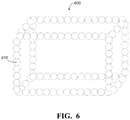
- FIG. 6 is a diagram of an example of a nanocube or cage structure.
- FIG. 7 is a diagram of an example of a nanoframe structure.
- FIG. 8A is a diagram of an example of a random alloy structure.
- FIG. 8B is a diagram of an example of an intermetallic structure.
- Typical SOFCs are prone to inefficiency due to impurity formation and reduced electronic and ionic transport. Poisoning due to contaminates such as sulfur in the fuel gas can occur.
- the anode layer of typical SOFC are known to react with the current collector causing resistance and instability.
- the anode structures and the SOFCs that use them enhance ionic and electronic conduction, improve poisoning tolerance and increase gas transport surface area, improving the overall power density of the SOFCs.
- a typical material used is a cermet made up of nickel mixed with the ceramic material that is used for the electrolyte in that particular cell, for example YSZ nanomaterial-based catalysts.
- nickel During operation of the SOFC, it is common for grains of nickel to form. Larger grains of nickel reduce the contact area that ions can be conducted through and reduces efficiency.
- the YSZ helps prevent grain growth of the nickel. Operation temperatures between 700° C. to 850° C. offer improved performance. The higher temperatures cause larger nickel particle formation that leads to reduced efficiency. In addition, crack formation on the catalyst layer during fuel starvation causes lower cell performance.
- FIG. 1 is a diagram of an example SOFC stack 100 .
- the SOFC stack 100 includes an interconnector 110 , an anode 120 , an electrolyte 130 , a cathode 140 , and an interconnector 150 .
- Interconnector 110 may be a bipolar plate. Interconnector 110 may also be referred to as a current collector and may be a metallic or a ceramic layer that is disposed on the anode 120 . Some examples of a ceramic interconnector composition may include lanthanum chromite and/or yttrium chromite. Suitable dopants for the ceramic interconnector composition may include nickel, cobalt, vanadium, calcium, strontium, magnesium, copper, manganese, and titanium. Some examples of a metallic interconnector composition may include chromia-based alloys, ferritic stainless steel, stainless steel, and iron/nickel-based super alloys.
- the interconnector 110 is used to connect two or more SOFCs in series to combine the electricity that each SOFC generates. Because the interconnector 110 is exposed to both the oxidizing and reducing side of the SOFC at high temperatures, it must be constructed from an extremely stable material.
- the anode 120 should exhibit catalytic properties and possess high porosity for the mass transport of reactant and product gases.
- the anodes disclosed herein may have a structure formed of a nickel-based cermet, although a ceria-based anode or a titanium-based anode are also contemplated.
- a nickel-based cermet that includes YSZ may be referred to as Ni/YSZ.
- Alternative anode cermet compositions may include a samaria-doped ceria (SDC), for example Ni/SDC or may include a gadolinium-doped ceria (GDC), for example Ni/GDC.
- SDC samaria-doped ceria
- GDC gadolinium-doped ceria
- Additional anode compositions may include a nickel-based catalyst containing mixtures of cobalt and/or dopants of precious metals such as palladium, rhodium, and/or platinum.
- the structure provides pathways of YSZ from the current collector 110 to the electrolyte 130 , improving ionic transport through the cell.
- the YSZ is coated with Ni, providing electron transport.
- the structure increases the surface areas for gas transport and the improved ionic and electronic conduction in the anode, decreasing the overpotentials associated with the adsorption/diffusion charge transfer step in the oxidation reaction. Improving the ionic and electronic conduction in the anode will also result in a reduction in cell operating temperature. Reducing the operating temperature will increase the redox and thermal stability and reliability of the anode.
- Electrolyte 130 is a dense electrolyte that is sandwiched between the anode 120 and the cathode 140 .
- the electrolyte 130 is an oxide conducting electrolyte that possesses a fluorite structure or perovskite structure.
- Cathode 140 is an air electrode that allows diffusion of gaseous oxygen towards the cathode/electrolyte interface.
- Cathode 140 compositions may include perovskite materials, for example, lanthanum strontium manganite (LSM)-based perovskites.
- Other example cathode 140 compositions may include Sr-doped lanthanum ferrite (LSF) materials and Sr-doped lanthanum ferro-cobaltite (LSCF) materials.
- Interconnector 150 may be a bipolar plate. Interconnector 150 may also be referred to as a current collector and may be a metallic or a ceramic layer that is disposed on the cathode 140 . Some examples of a ceramic interconnector composition may include lanthanum chromite and/or yttrium chromite. Suitable dopants for the ceramic interconnector composition may include nickel, cobalt, vanadium, calcium, strontium, magnesium, copper, manganese, and titanium. Some examples of a metallic interconnector composition may include chromia-based alloys, ferritic stainless steel, stainless steel, and iron/nickel-based super alloys.
- the interconnector 150 is used to connect two or more SOFCs in series to combine the electricity that each SOFC generates. Because the interconnector 150 is exposed to both the oxidizing and reducing side of the SOFC at high temperatures, it must be constructed from an extremely stable material.
- FIG. 2 is a diagram of an example anode layer 200 of the SOFC stack of FIG. 1 .
- the anode layer 200 is in contact with a current collector 210 and a solid electrolyte layer 220 .
- the current collector 210 may be a ferritic steel or any other suitable material.
- the anode layer 200 is a Ni—YSZ anode that includes YSZ particles 230 and Ni particles 240 (shown in stippling) that each extend between the current collector 210 and the solid electrolyte layer 220 .
- the Ni—YSZ anode is shown merely for example, and it is understood that the anode layer 200 may be constructed of any suitable material.
- FIG. 3 is a diagram of an example embodiment showing a cross-sectional view of an anode layer 300 coated in a catalyst material.
- the anode layer 300 extends between a current collector 310 and a solid electrolyte layer 320 .
- the current collector 310 may be a ferritic steel or any other suitable material.
- the anode layer 300 is a Ni—YSZ anode that includes YSZ particles 330 and Ni particles 340 (shown in stippling) that each extend between the current collector 310 and the solid electrolyte layer 320 .
- the Ni—YSZ anode is shown merely for example, and it is understood that the anode layer 300 may be constructed of any suitable material.
- the anode layer 300 may be any suitable material including, but not limited to, NiO/SDC or Ni/ScSZ-10.
- the anode layer 300 is coated with a catalyst material 350 .
- the catalyst material 350 may be deposited onto the anode using an atomic layer deposition (ALD) technique.
- ALD atomic layer deposition
- the ALD technique may be a thin-film deposition technique based on the sequential use of a gas phase chemical process.
- the catalyst material 350 may increase the cell performance, lower the operating temperature to 300° C. to 400° C., and prevent crack formation during fuel starvation, thereby making it a suitable application for automobiles.
- the catalyst material 350 may include an active material such as a Pt, Pd, or PtPd alloy and may be solid or porous.
- An inner core of the catalyst material 350 may include the active material and any suitable metal such as, for example, Ni, Co, and/or Fe.
- the catalyst material 350 may include an outer shell of Pt and an inner core of Pt—Ni.
- the outer shell may be 3-5 atoms in thickness.
- the Pt outer shell may lower the operating temperature of the cell.
- the Pt outer shell may be replaced by Pd, Au, or Ag based on the type of fuel being employed.
- the catalyst material 350 may be a core-shell structure as shown in FIGS. 4A and 4B , a layered structure as shown in FIG. 5 , a nanocube or cage structure as shown in FIG. 6 , a nanoframe structure as shown in FIG. 7 , or a random porous structure such as a random alloy structure shown in FIG. 8A or an intermetallic structure shown in FIG. 8B .
- FIG. 4A is a diagram of a cross-sectional view of an example of a core-shell structure catalyst material coating deposited on an anode layer 400 .
- the anode layer 400 extends between a current collector 410 and a solid electrolyte layer 420 .
- the current collector 410 may be a ferritic steel or any other suitable material.
- the anode layer 400 is a Ni—YSZ anode that includes YSZ particles 430 and Ni particles 440 (shown in stippling) that each extend between the current collector 410 and the solid electrolyte layer 420 .
- the Ni—YSZ anode is shown merely for example, and it is understood that the anode layer 400 may be constructed of any suitable material.
- the anode layer 400 may be any suitable material including, but not limited to, NiO/SDC or Ni/ScSZ-10.
- the anode layer 400 is coated with a catalyst material 450 .
- the catalyst material 450 is a core-shell structure that has an outer shell 460 and an inner core 470 (shown in stippling).
- the outer shell 460 may be Pt, Pd, Au, or Ag.
- the outer shell may have a thickness of 3-5 atoms, and it may be solid or porous. In an example where the outer shell 460 is porous, the outer shell may have a pore diameter of 2 nm to 50 nm.
- the inner core 470 may be Pt—Ni.
- the inner core 470 may have a thickness between 7 nm and 50 nm.
- the inner core 470 may be microporous having a porosity of less than 2 nm.
- the Pt—Ni may form a random alloy as shown in FIG. 8A or an intermetallic structure as shown in FIG. 8B .
- the core-shell structure catalyst material 450 may be deposited on the anode layer 400 as a nanocube or cage structure as shown in FIG. 6 or a nanoframe structure as shown in FIG. 7 .
- the Ni—YSZ anode is shown merely for example, and it is understood that the anode layer 400 may be constructed of any suitable material.
- the anode layer 400 may be any suitable material including, but not limited to, NiO/SDC or Ni/ScSZ-10.
- the anode layer 400 is coated with a catalyst material 450 .
- the catalyst material 450 is a core-shell structure that has an outer shell 460 and an inner core that includes a first sublayer 475 (shown in dark stippling) and a second sublayer 480 (shown in light stippling).
- the inner core is shown to have two sublayers, however some embodiments may have an inner core with more than two sublayers.
- the first sublayer 475 is adjacent to and in contact with the outer shell 460 .
- the first sublayer 475 may be solid or it may contain up to 10% of micropores.
- the second sublayer 480 may have a greater porosity than the first sublayer 475 .
- the porosity of the second sublayer 480 may be in the mesoporous range, for example 2 nm to 50 nm.
- the first sublayer 475 and the second sublayer 480 may each have a thickness of 2 nm to 5 nm.
- the outer shell 460 may be Pt, Pd, Au, or Ag.
- the outer shell 460 may have a thickness of 3-5 atoms, and it may be solid or porous. In an example where the outer shell 460 is porous, the outer shell may have a pore diameter of 2 nm to 50 nm.
- the first sublayer 475 and the second sublayer 480 may each be Pt—Ni or they may each be different materials.
- the Pt—Ni may form a random alloy as shown in FIG. 8A or an intermetallic structure as shown in FIG. 8B .
- the core-shell structure catalyst material 450 may be deposited on the anode layer 400 as a nanocube or cage structure as shown in FIG. 6 or a nanoframe structure as shown in FIG. 7 .
- FIG. 5 is a diagram of a cross-sectional view of the example embodiment of a layered catalyst material coating deposited on an anode layer 500 .
- the anode layer 500 extends between a current collector 510 and a solid electrolyte layer 520 .
- the current collector 510 may be a ferritic steel or any other suitable material.
- the anode layer 500 is a Ni—YSZ anode that includes YSZ particles 430 and Ni particles 540 (shown in stippling) that each extend between the current collector 510 and the solid electrolyte layer 520 .
- the Ni—YSZ anode is shown merely for example, and it is understood that the anode layer 500 may be constructed of any suitable material.
- the anode layer 500 may be any suitable material including, but not limited to, NiO/SDC or Ni/ScSZ-10.
- the anode layer 500 is coated with a catalyst material 550 .
- the catalyst material 550 is a layered structure that has an outer shell 560 and a base layer that includes a first sublayer 575 (shown in dark stippling) and a second sublayer 580 (shown in light stippling).
- the base layer is shown to have two sublayers, however some embodiments may have a single layer base layer or a base layer with more than two sublayers.
- the first sublayer 575 is adjacent to and in contact with the outer shell 560 .
- the first sublayer 575 may be solid or it may contain up to 10% of micropores.
- the second sublayer 580 may have a greater porosity than the first sublayer 575 .
- the porosity of the second sublayer 580 may be in the mesoporous range, for example 2 nm to 50 nm.
- the first sublayer 575 and the second sublayer 480 may each have a thickness of 2 nm to 5 nm.
- the outer shell 560 may be Pt, Pd, Au, or Ag.
- the outer shell 560 may have a thickness of 3-5 atoms, and it may be solid or porous. In an example where the outer shell 560 is porous, the outer shell may have a pore diameter of 2 nm to 50 nm.
- the first sublayer 575 and the second sublayer 580 may each be Pt—Ni.
- the Pt—Ni may form a random alloy as shown in FIG. 8A or an intermetallic structure as shown in FIG. 8B .
- FIG. 6 is a diagram of an example of a nanocube 600 or cage structure.
- the nanocube 600 is constructed of particles 610 .
- Each particle 610 represents a core-shell catalyst material structure as described in FIGS. 4A and 4B .
- the arrangement of particles 610 creates an open structure with a pore size in the mesoporous region.
- the pore size created may be 2 nm to 50 nm.
- FIG. 7 is a diagram of an example of a nanoframe structure 700 .
- the nanoframe structure 700 is constructed of particles 710 .
- Each particle 710 represents a core-shell catalyst material structure as described in FIGS. 4A and 4B .
- the arrangement of particles 710 creates an open structure with a pore size in the mesoporous region.
- the pore size created may be 2 nm to 50 nm.
- FIG. 8A is a diagram of an example of a random alloy structure 800 .
- the random alloy structure 800 is an example construction of the inner core and/or sublayers described in FIGS. 3, 4A, 4B, and 5 .
- the random alloy structure 800 may include particles 810 containing an active material such as Pt or Pd and any suitable metal such as, for example, Ni, Co, and/or Fe.
- each particle 810 is a Pt—Ni particle.
- FIG. 8B is a diagram of an example of an intermetallic structure 850 .
- the intermetallic structure 850 is an example construction of the inner core and/or sublayers described in FIGS. 3, 4A, 4B, and 5 .
- the intermetallic structure 850 may include particles containing an active material such as Pt or Pd and any suitable metal such as, for example, Ni, Co, and/or Fe.
- particle 860 may be a Pt particle and particle 870 may be a Ni particle together which form a Pt—Ni intermetallic compound.
Landscapes
- Chemical & Material Sciences (AREA)
- General Chemical & Material Sciences (AREA)
- Electrochemistry (AREA)
- Chemical Kinetics & Catalysis (AREA)
- Engineering & Computer Science (AREA)
- Sustainable Development (AREA)
- Sustainable Energy (AREA)
- Life Sciences & Earth Sciences (AREA)
- Manufacturing & Machinery (AREA)
- Ceramic Engineering (AREA)
- Materials Engineering (AREA)
- Composite Materials (AREA)
- Inert Electrodes (AREA)
- Catalysts (AREA)
Abstract
Description
Claims (10)
Priority Applications (1)
| Application Number | Priority Date | Filing Date | Title |
|---|---|---|---|
| US15/882,376 US10637070B2 (en) | 2018-01-29 | 2018-01-29 | Highly porous anode catalyst layer structures for fuel flexible solid oxide fuel cells |
Applications Claiming Priority (1)
| Application Number | Priority Date | Filing Date | Title |
|---|---|---|---|
| US15/882,376 US10637070B2 (en) | 2018-01-29 | 2018-01-29 | Highly porous anode catalyst layer structures for fuel flexible solid oxide fuel cells |
Publications (2)
| Publication Number | Publication Date |
|---|---|
| US20190237770A1 US20190237770A1 (en) | 2019-08-01 |
| US10637070B2 true US10637070B2 (en) | 2020-04-28 |
Family
ID=67393709
Family Applications (1)
| Application Number | Title | Priority Date | Filing Date |
|---|---|---|---|
| US15/882,376 Active 2038-06-02 US10637070B2 (en) | 2018-01-29 | 2018-01-29 | Highly porous anode catalyst layer structures for fuel flexible solid oxide fuel cells |
Country Status (1)
| Country | Link |
|---|---|
| US (1) | US10637070B2 (en) |
Citations (4)
| Publication number | Priority date | Publication date | Assignee | Title |
|---|---|---|---|---|
| US20080090127A1 (en) | 2006-07-12 | 2008-04-17 | Gorte Raymond J | High-performance ceramic anodes for use with strategic and other hydrocarbon fuels |
| KR20120121570A (en) * | 2011-04-27 | 2012-11-06 | 한국세라믹기술원 | The method of forming Ni/YSZ core-shell by high speed mixing and use it manufacturing method for uniform nano-structure arrays by heat treatments |
| US20150064607A1 (en) | 2013-08-30 | 2015-03-05 | Korea Institute Of Science And Technology | Catalyst for hydrocarbon-fueled solid oxide fuel cell and production method thereof |
| US20170062799A1 (en) * | 2014-12-15 | 2017-03-02 | West Virginia University | Nanoscale sofc electrode architecture engineered using atomic layer deposition |
-
2018
- 2018-01-29 US US15/882,376 patent/US10637070B2/en active Active
Patent Citations (4)
| Publication number | Priority date | Publication date | Assignee | Title |
|---|---|---|---|---|
| US20080090127A1 (en) | 2006-07-12 | 2008-04-17 | Gorte Raymond J | High-performance ceramic anodes for use with strategic and other hydrocarbon fuels |
| KR20120121570A (en) * | 2011-04-27 | 2012-11-06 | 한국세라믹기술원 | The method of forming Ni/YSZ core-shell by high speed mixing and use it manufacturing method for uniform nano-structure arrays by heat treatments |
| US20150064607A1 (en) | 2013-08-30 | 2015-03-05 | Korea Institute Of Science And Technology | Catalyst for hydrocarbon-fueled solid oxide fuel cell and production method thereof |
| US20170062799A1 (en) * | 2014-12-15 | 2017-03-02 | West Virginia University | Nanoscale sofc electrode architecture engineered using atomic layer deposition |
Also Published As
| Publication number | Publication date |
|---|---|
| US20190237770A1 (en) | 2019-08-01 |
Similar Documents
| Publication | Publication Date | Title |
|---|---|---|
| EP2229704B1 (en) | High performance multilayer electrodes for use in reducing gases | |
| JP5608674B2 (en) | Current collector for solid oxide fuel cell stack | |
| JP5260052B2 (en) | Solid oxide fuel cell | |
| US7445814B2 (en) | Methods of making porous cermet and ceramic films | |
| EP2772974B1 (en) | Porous current collector, method for manufacturing same, and fuel cell that uses porous current collector | |
| US20090148743A1 (en) | High performance multilayer electrodes for use in oxygen-containing gases | |
| Tao et al. | A mini-review of carbon-resistant anode materials for solid oxide fuel cells | |
| JP2018055946A (en) | Anode for solid oxide fuel cell, method for producing the same, and solid oxide fuel cell | |
| JP2009193775A (en) | ELECTROCHEMICAL CELL AND ITS MANUFACTURING METHOD AND OPERATION METHOD | |
| JP7617799B2 (en) | Bonding material, electrochemical module, electrochemical device, solid oxide fuel cell, solid oxide electrolysis cell, energy system, and method for manufacturing electrochemical module | |
| US10411267B2 (en) | Highly porous cathode catalyst layer structures for flexible solid oxide fuel cell applications in vehicles | |
| US10637070B2 (en) | Highly porous anode catalyst layer structures for fuel flexible solid oxide fuel cells | |
| JP2018181745A (en) | Conductive member, electrochemical reaction unit, and electrochemical reaction cell stack | |
| US20260117405A1 (en) | Separator for electrochemical device, electrochemical device | |
| WO2019167437A1 (en) | Fuel cell | |
| US20250096284A1 (en) | Solid oxide electrochemical device unit cell | |
| US10910662B2 (en) | Structured anode for a solid oxide fuel cell | |
| Coutinho Antunes et al. | How Would Solid Oxide Fuel Cells and Bioethanol Impact in Electric Mobility Transition? | |
| WO2017002264A1 (en) | Solid oxide fuel cell and method for manufacturing same | |
| JP2006147207A (en) | Solid oxide fuel cell and manufacturing method thereof | |
| JP2005276534A (en) | Solid oxide fuel cell | |
| JP2005276536A (en) | Solid oxide fuel cell |
Legal Events
| Date | Code | Title | Description |
|---|---|---|---|
| AS | Assignment |
Owner name: NISSAN NORTH AMERICA, INC., TENNESSEE Free format text: ASSIGNMENT OF ASSIGNORS INTEREST;ASSIGNORS:GUMECI, CENK;THOMPSON, DAVID;REEL/FRAME:044756/0650 Effective date: 20180126 |
|
| FEPP | Fee payment procedure |
Free format text: ENTITY STATUS SET TO UNDISCOUNTED (ORIGINAL EVENT CODE: BIG.); ENTITY STATUS OF PATENT OWNER: LARGE ENTITY |
|
| STPP | Information on status: patent application and granting procedure in general |
Free format text: NON FINAL ACTION MAILED |
|
| STPP | Information on status: patent application and granting procedure in general |
Free format text: RESPONSE TO NON-FINAL OFFICE ACTION ENTERED AND FORWARDED TO EXAMINER |
|
| STPP | Information on status: patent application and granting procedure in general |
Free format text: NOTICE OF ALLOWANCE MAILED -- APPLICATION RECEIVED IN OFFICE OF PUBLICATIONS |
|
| STCF | Information on status: patent grant |
Free format text: PATENTED CASE |
|
| AS | Assignment |
Owner name: NISSAN MOTOR CO., LTD., JAPAN Free format text: ASSIGNMENT OF ASSIGNORS INTEREST;ASSIGNOR:NISSAN NORTH AMERICA, INC.;REEL/FRAME:054512/0143 Effective date: 20200922 |
|
| MAFP | Maintenance fee payment |
Free format text: PAYMENT OF MAINTENANCE FEE, 4TH YEAR, LARGE ENTITY (ORIGINAL EVENT CODE: M1551); ENTITY STATUS OF PATENT OWNER: LARGE ENTITY Year of fee payment: 4 |