US10633896B1 - Theft resistant locking device for a roll-up door - Google Patents
Theft resistant locking device for a roll-up door Download PDFInfo
- Publication number
- US10633896B1 US10633896B1 US15/073,025 US201615073025A US10633896B1 US 10633896 B1 US10633896 B1 US 10633896B1 US 201615073025 A US201615073025 A US 201615073025A US 10633896 B1 US10633896 B1 US 10633896B1
- Authority
- US
- United States
- Prior art keywords
- hook
- catch
- arm
- latch hook
- door
- Prior art date
- Legal status (The legal status is an assumption and is not a legal conclusion. Google has not performed a legal analysis and makes no representation as to the accuracy of the status listed.)
- Active, expires
Links
- 230000014759 maintenance of location Effects 0.000 claims description 38
- 230000000717 retained effect Effects 0.000 claims description 21
- 230000009977 dual effect Effects 0.000 abstract description 2
- 239000011800 void material Substances 0.000 description 4
- 229910000760 Hardened steel Inorganic materials 0.000 description 1
- 241000050998 Vasconcellea x heilbornii Species 0.000 description 1
- 238000007599 discharging Methods 0.000 description 1
- 230000000694 effects Effects 0.000 description 1
- 238000000034 method Methods 0.000 description 1
- 238000003466 welding Methods 0.000 description 1
Images


Classifications
-
- E—FIXED CONSTRUCTIONS
- E05—LOCKS; KEYS; WINDOW OR DOOR FITTINGS; SAFES
- E05B—LOCKS; ACCESSORIES THEREFOR; HANDCUFFS
- E05B83/00—Vehicle locks specially adapted for particular types of wing or vehicle
- E05B83/02—Locks for railway freight-cars, freight containers or the like; Locks for the cargo compartments of commercial lorries, trucks or vans
- E05B83/04—Locks for railway freight-cars, freight containers or the like; Locks for the cargo compartments of commercial lorries, trucks or vans for sliding wings
-
- E—FIXED CONSTRUCTIONS
- E05—LOCKS; KEYS; WINDOW OR DOOR FITTINGS; SAFES
- E05B—LOCKS; ACCESSORIES THEREFOR; HANDCUFFS
- E05B85/00—Details of vehicle locks not provided for in groups E05B77/00 - E05B83/00
- E05B85/20—Bolts or detents
- E05B85/24—Bolts rotating about an axis
-
- E—FIXED CONSTRUCTIONS
- E05—LOCKS; KEYS; WINDOW OR DOOR FITTINGS; SAFES
- E05B—LOCKS; ACCESSORIES THEREFOR; HANDCUFFS
- E05B63/00—Locks or fastenings with special structural characteristics
- E05B63/14—Arrangement of several locks or locks with several bolts, e.g. arranged one behind the other
-
- E—FIXED CONSTRUCTIONS
- E05—LOCKS; KEYS; WINDOW OR DOOR FITTINGS; SAFES
- E05B—LOCKS; ACCESSORIES THEREFOR; HANDCUFFS
- E05B65/00—Locks or fastenings for special use
- E05B65/0021—Locks or fastenings for special use for overhead or roll-up doors, e.g. garage doors
-
- E—FIXED CONSTRUCTIONS
- E05—LOCKS; KEYS; WINDOW OR DOOR FITTINGS; SAFES
- E05B—LOCKS; ACCESSORIES THEREFOR; HANDCUFFS
- E05B83/00—Vehicle locks specially adapted for particular types of wing or vehicle
- E05B83/02—Locks for railway freight-cars, freight containers or the like; Locks for the cargo compartments of commercial lorries, trucks or vans
-
- E—FIXED CONSTRUCTIONS
- E05—LOCKS; KEYS; WINDOW OR DOOR FITTINGS; SAFES
- E05B—LOCKS; ACCESSORIES THEREFOR; HANDCUFFS
- E05B17/00—Accessories in connection with locks
- E05B17/0025—Devices for forcing the wing firmly against its seat or to initiate the opening of the wing
-
- E—FIXED CONSTRUCTIONS
- E05—LOCKS; KEYS; WINDOW OR DOOR FITTINGS; SAFES
- E05B—LOCKS; ACCESSORIES THEREFOR; HANDCUFFS
- E05B65/00—Locks or fastenings for special use
- E05B65/08—Locks or fastenings for special use for sliding wings
- E05B65/0811—Locks or fastenings for special use for sliding wings the bolts pivoting about an axis perpendicular to the wings
-
- Y—GENERAL TAGGING OF NEW TECHNOLOGICAL DEVELOPMENTS; GENERAL TAGGING OF CROSS-SECTIONAL TECHNOLOGIES SPANNING OVER SEVERAL SECTIONS OF THE IPC; TECHNICAL SUBJECTS COVERED BY FORMER USPC CROSS-REFERENCE ART COLLECTIONS [XRACs] AND DIGESTS
- Y10—TECHNICAL SUBJECTS COVERED BY FORMER USPC
- Y10T—TECHNICAL SUBJECTS COVERED BY FORMER US CLASSIFICATION
- Y10T292/00—Closure fasteners
- Y10T292/08—Bolts
- Y10T292/0911—Hooked end
- Y10T292/0937—Gravity actuated
-
- Y—GENERAL TAGGING OF NEW TECHNOLOGICAL DEVELOPMENTS; GENERAL TAGGING OF CROSS-SECTIONAL TECHNOLOGIES SPANNING OVER SEVERAL SECTIONS OF THE IPC; TECHNICAL SUBJECTS COVERED BY FORMER USPC CROSS-REFERENCE ART COLLECTIONS [XRACs] AND DIGESTS
- Y10—TECHNICAL SUBJECTS COVERED BY FORMER USPC
- Y10T—TECHNICAL SUBJECTS COVERED BY FORMER US CLASSIFICATION
- Y10T292/00—Closure fasteners
- Y10T292/08—Bolts
- Y10T292/1039—Swinging and camming
Definitions
- This invention relates to locking devices for securing doors and more specifically to a locking device for securing roll-up doors on cargo vehicles.
- Tractor-trailer rigs present promising targets to criminals due to the large quantity of high-value cargo they contain.
- a popular point of access on a trailer is through the rear roll-up doors, which have locks that are often easily breached or removed.
- One such easily breached lock type is the Truk-Lok II made by Babaco Alarm Systems, Inc. This type of lock is ubiquitous and a common method of breaching this lock is to slide a jacking device beneath the roll up door and apply upward force with the jack until the lock breaks at its failure points.
- U.S. Pat. No. 3,893,722 issued to Galbreath et al. discloses a lock assembly wherein a hand lever operates an arcuate latch hook which engages a catch pin.
- the hand lever is elongate and spans across a distance to a separate key-lock assembly which locks the lever in place.
- a drawback to this design is that the hand lever can be sawed in half, thus freeing the hand lever from the lock assembly to allow the cargo door to be opened.
- Other designs merely padlock the hand lever in place; however these designs are easily breached by defeating the padlock.
- the invention is a locking device for securing roll-up doors on tractor trailers and other cargo vehicles.
- the working parts of the invention are enclosed inside of a housing and the invention employs a twin catch-pin system which allows the door to be locked shut with minimal play between the bottom of the door and trailer deck.
- the invention is resistant to attempts to slide pry bars or jacks under the door in force breach attempts.
- the locking device achieves a closed and locked position, attempts to open the locking device by forcing the hand lever are thwarted.
- the invention When the invention is placed in an open position, it is designed to remain in the open position until the door is shut again. It is also designed to achieve the closed and locked position when the door is shut and the catch arm contacts a first upper catch pin, thus causing an arcuate latch hook to release and engage around a second lower catch pin.
- the catch arm When the door is lowered so the catch arm contacts the upper catch pin, the remaining working parts of the locking device are set in motion such that the door closes and locks by itself. If a user desires to open the door, the device must be unlocked and a hand lever rotated to an open position, which resets the locking device into an open position awaiting the next closing of the door.
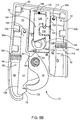
- FIG. 1 is a front perspective view of the locking device of the present invention.
- FIG. 2 is rear perspective view of the locking device of the present invention.
- FIG. 3A is a plan view of the catch assembly of the locking device of the present invention.
- FIG. 3B is a perspective view of the catch assembly, with upper and lower catch pins shown in phantom.
- FIG. 4A is a semi-phantom view of the locking device shown attached to the interior surface of a roll-up door, the locking device being in the open position.
- FIG. 4B is a semi-phantom view of the locking device shown attached to the interior surface of a roll-up door, the locking device being in the closed position.
- FIG. 5A is a plan view of the locking device, shown with the rear face of its housing removed so that the working parts are visible, this view indicating the latch hook in the disengaged position.
- FIG. 5B is a plan view of the locking device, shown with the rear face of its housing removed so that the working parts are visible, this view indicating the latch hook in the engaged position.
- FIG. 6A is a close-up plan view of the locking assembly of the locking device as it would appear in the open position.
- FIG. 6B is a close-up plan view of the locking assembly of the locking device as it would appear in the closed and locked position.
- the exterior front and rear views of the inventive locking device 10 is shown in FIGS. 1 and 2 , respectively.
- the locking device 10 is comprised of a housing 12 which retains all of the internal working parts of the locking device. In this view, the only internal working parts visible are the bottom of the catch arm 14 and the arcuate latch hook 16 .
- a key lock 18 is mounted in lock retainer 20 on the housing 12 .
- the lock retainer 20 mounts through a roll-up door 24 on a cargo vehicle 54 (See FIGS. 4A and 4B ), and has a sidewall 22 of a height sufficient for protruding through a roll-up door 24 so that the key lock 18 mounts relatively flush and is accessible from the exterior side 26 of a roll-up door 24 .
- the front face 28 of the housing 12 rests against the interior side 25 of a roll up door 24 and is retained on the door by a plurality of bolts 30 which penetrate the door 24 and housing 12 at bolt holes 32 .
- Bolts 30 are preferably of an inaccessible variety such as round-head bolts.
- the rear face 33 of housing 12 is shown in FIG. 2 , and shows nut keepers 34 , which have a round cavity 36 for placing nuts (not shown) in perfect alignment with bolt holes 32 so that bolts 30 can easily engage nuts for tightening and thereby retaining the locking device 10 on the interior side 25 of a roll-up door 24 .
- axle 38 which attaches to arcuate latch hook 16 is retained in roller bearings 40 which are mounted in bearing races 42 , 44 on the front face 28 and rear face 33 of housing 12 respectively.
- Latch hook 16 is joined to axle 38 and rotates in the direction that axle 38 rotates.
- axle 38 is a length sufficient to protrude through a roll-up door 24 and attach a hand lever 46 . Articulating the hand lever 46 rotates axle 38 and engages and disengages arcuate latch hook 16 with lower catch pin 74 of catch assembly 50 .
- the catch assembly 50 is shown in FIGS. 3A-3B , the catch assembly 50 mounts flushly with a loading deck 52 of a cargo vehicle 54 , and is attached to the loading deck 52 by welding. Also, while a vehicle loading deck application is shown, in FIGS. 4A and 4B , catch assembly 50 could be mounted flushly in the floor of a storage unit, warehouse, or other structure employing a roll-up door. The catch assembly 50 is positioned beneath a roll-up door 24 in the loading deck 52 to lockingly engage the locking device 10 that is attached to the interior side 25 of a roll-up door 24 .
- the catch assembly 50 is comprised of an elongated, substantially rectangular casing 56 having a pair of sidewalls 58 and 60 and a pair of end walls 62 and 64 .
- the sidewalls 58 , 60 and the end walls 62 , 64 define a catch chamber 66 which preferably opens upwardly to receive the latch hook 16 and catch arm 14 and opens downwardly for drainage.
- a floor portion 68 borders the downward openings 70 and provides structural integrity.
- Catch assembly 50 employs two catch pins mounted in the catch assembly at differing heights. As shown in the Figures, an upper catch pin 72 and a lower catch pin 74 are mounted between sidewalls 58 , 60 .
- FIG. 4A shows the locking device 10 attached to a roll-up door 24 on a cargo vehicle 54 , this being a tractor-trailer.
- the latch hook 16 of locking device 10 is in the disengaged position 71 as it would appear when door 24 is opened.
- the upper catch pin 72 is aligned to contact the beveled bottom portion 76 of the catch arm 14 causing it to pivot in an arc, which sets in motion the release of the latch hook 16 from a retained position as will be described further herein.
- the latch hook 16 When the latch hook 16 is released, it rotates downward and engages beneath lower catch pin 74 and locks in place, with the door 24 in the fully closed position as shown in FIG. 4B .
- the locking device 10 With the door closed, the locking device 10 is hidden from access and the engagement upon dual catch pins 72 , 74 effectively gathers up any slack between the bottom 78 of the roll-up door 24 and the loading deck 52 .
- the key lock 18 To reopen the locking device 10 , the key lock 18 must be engaged and rotated to an open position to release the latch hook 16 from its locked position and the hand lever 46 is then rotated towards an open position, until the latch hook 16 is reset to its disengaged position 71 . Once in its disengaged position 71 the latch hook 16 will be retained there despite any vibration or activity from operating the roll-up door 24 .
- a shroud 80 protects catch arm 14 .
- Shroud 80 partially encloses the catch arm 14 and protects it from damage due to contacting the casing 56 of catch assembly 50 as roll-up door 24 is closed.
- the shroud 80 prevents catch arm 14 from being snagged or bent due to operators harshly closing roll-up door 24 , which can be a frequent occurrence during the working life of a roll-up door.
- FIG. 5A illustrates the invention with the rear face 33 of housing 12 removed which shows the interior 82 of housing 12 with the working parts of the inventive locking device 10 exposed.
- the interior 82 of housing 12 is defined by an upper end 84 , a lower end 86 , and interior side 88 of front face 28 and sidewalls 90 a , 90 b , and 90 c .
- the latch hook 16 is shown in its disengaged reset position 71 , the way it might appear when locking device 10 is attached to an open roll-up door 24 .
- Axle 38 extends through latch hook 16 and associated roller bearing 40 which seats in the bearing race 44 of the rear face 33 of housing 12
- An additional roller bearing (not seen in this view) bears against latch hook 16 on its opposite side and seats in bearing race 42 of front face 28 of housing 12 .
- the remaining working parts likewise appear as they should for the inventive locking device 10 being in the open position on an open roll-up door 24 .
- Latch hook 16 is retained in its disengaged position 71 by latch hook keeper 92 which inserts into latch hook retaining notch 94 of catch arm 14 .
- Catch arm 14 is biased by catch arm spring 96 , which is retained in spring retaining notch 98 of catch arm 14 and an opposite retaining notch 100 imparted into sidewall 90 a of housing 12 .
- Catch arm 14 rotates on a pivot pin 102 attached to housing 12 , the pivot pin 102 pivotally engaging the upper end 104 of catch arm 14 .
- the lower end 106 of catch arm 14 is free to swing in an arc limited by the biasing force afforded by catch arm spring 96 and its contact against latch hook 16 .
- Latch hook 16 in turn is biased against pushing arm 108 which places a pushing force against the outer curved side 110 of latch hook and urges latch hook to rotate towards catch arm 14 until achieving an engaged position 73 around lower catch pin 74 of the locking device 10 as shown in FIGS. 4B and 5B .
- Pushing arm 108 pivots at a pivot pin 112 on its upper end 114 , pivot pin 112 being attached to housing 12 .
- FIG. 5B illustrates how the working parts of the inventive locking device appear when latch hook 16 is in an engaged position 73 .
- catch arm 14 pivots toward sidewall 90 a and catch arm spring 96 is compressed.
- latch hook keeper 92 of latch hook 16 is freed of latch hook retaining notch 94 and pushing arm 108 forces latch hook 16 to rotate toward an engaged position 73 beneath lower catch pin 74 of catch assembly 50 .
- Pushing arm 108 is biased by pushing arm spring 116 which is retained in a notch 118 in pushing arm 108 and a notch 120 in sidewall 90 b .
- catch arm 14 When roll-up door 24 is in the fully closed position, upper catch pin 72 is retained in upper catch pin notch 122 of catch arm 14 . Retention is assured, as catch arm spring 96 biases catch arm 14 tightly against upper catch pin 72 .
- Upper catch pin notch 122 is sized to flushly retain upper catch pin 72 therein with a minimal amount of play, thus insuring a tight engagement between the bottom 78 of a roll-up door 24 and the loading deck 52 of a cargo vehicle 54 . Due to the tight engagement provided by the invention, forced breaches from inserting crowbars or jacks under a roll-up door mounting the invention are greatly prevented. It is preferable that catch arm 14 is constructed from hardened steel to resist wear, thus retaining a tight engagement with upper catch pin 72 , despite repeated usage.
- FIG. 6A shows a close up of the locking assembly 124 as it would appear in the open position with latch hook 16 in the disengaged position 71 .
- FIG. 6B shows a similar close up of the locking assembly 124 as it would appear in the closed and locked position with door 24 closed and latch hook 16 in the engaged position 73 .
- the locking assembly 124 is comprised of a vertical hook member 126 and a hook retention member 128 .
- a portion of the pushing arm 108 is also shown in this view to illustrate the engagement of the hook retention member 128 with the pushing arm 108 .
- Vertical hook member 126 is retained in a retention chamber 130 of the interior side 88 of front face 28 of housing 12 , retention chamber 130 being defined by sidewalls 132 a , 132 b , 132 c , 132 d and 132 e .
- Vertical hook member 126 moves vertically within retention chamber 130 and movement is facilitated by vertical hook member spring 134 which biases vertical hook member 126 against sidewall 132 b .
- Vertical hook member spring 134 is retained in a notch 136 in sidewall 132 b and preferably, a cavity imparted into the top side 138 of vertical hook member 126 .
- Vertical hook member 126 has an interior void 140 and a downwardly depending hook 142 adjacent the top 141 of interior void 140 .
- Interior void 140 provides space in which hook retention member 128 can advance into to achieve a locked position.
- Hook retention member 128 advances and retreats between sidewalls 132 c and 132 d of retention chamber 130 .
- Sidewalls 132 c and 132 d act to guide hook retention member 128 into its engagement and disengagement with downwardly depending hook 142 .
- Hook retention member 128 has a notch 144 into which downwardly depending hook 142 advances to lock the locking assembly 124 , and thereby lock the entire device 10 upon door 24 being closed.
- latch hook 16 is engaged 73 around lower catch pin 74 and locked in its engaged position 73 by locking assembly 124 .
- Beveled side 146 of vertical hook member 126 acts as a contacting surface for the lever 148 of the key lock 18 to act against.
- the vertical hook member 126 travels vertically upward a sufficient distance to disengage downwardly depending hook 142 from notch 144 of hook retention member 128 .
- Hook retention member 128 pivotally engages with pushing arm 108 to allow sufficient range of motion for hook retention member 128 to horizontally advance into interior void 140 and engage with downwardly depending hook 142 (locked position show in FIG. 6B ) and then horizontally travel in reverse to an unlocked position (See FIG. 6A ) upon unlocking downwardly depending hook 142 from notch 144 with key lock 18 .
- Hook retention member 128 includes a male end portion 152 which inserts into a side slot 153 on the side of pushing arm 108 wherein the two parts are joined by a pivot pin (not shown). Side slot 153 extends above and below male end portion 152 a sufficient distance to allow pushing arm 108 enough range of motion to pivot on its upper pivot pin 112 and impart its pushing force to latch hook 16 .
- the smooth engagement and disengagement of downwardly depending hook 142 and hook retention member 128 is greatly enhanced by hook retention member having a rounded end 154 for hook 142 to travel against.
- a cargo load placed into a vehicle using the inventive locking device would be locked as soon as the roll-up door on the vehicle is closed.
- merely dropping a roll-up door 24 into a closed position would cause the catch arm 14 to engage the upper catch pin 72 of the catch assembly 50 , causing the latch hook 16 to be released from its retained position and pushed into an engaged position around lower catch pin 74 by pushing arm 108 .
- a roll-up door 24 employing the invention 10 would be closed and locked tight and the user could apply a seal to the load, if desired.
- the user merely has to engage the key lock 18 , rotate it to the open position and push the hand lever 46 toward the open position once key lock disengages vertical hook member 126 from hook retention member 128 .
- the latch hook 16 rotates until keeper 92 is engaged in retaining notch 94 in catch arm 14 ; this being the retained position. This rotation of latch hook 16 also pushes latch hook against pushing arm 108 , thus biasing pushing arm against latch hook in the open position.
- the locking device of the present invention can have applications outside of vehicle applications.
- roll-up doors are applicable in many areas such as warehouse and storage units, to name some.
Abstract
The invention is a locking device for securing roll-up doors on tractor trailers and other cargo vehicles. The working parts of the invention are enclosed inside a housing and the invention employs a dual catch-pin system which allows the door to be locked shut with minimal play between the bottom of the door and loading deck of the cargo vehicle. This, the invention is resistant to attempts to slide pry bars or jacks under the door in force breach attempts.
Description
This application claims the benefit of U.S. Provisional Patent Application No. 62/133,996, filed on Mar. 17, 2015
This invention relates to locking devices for securing doors and more specifically to a locking device for securing roll-up doors on cargo vehicles.
On road theft from tractor-trailer rigs and other cargo vehicles has been an ongoing problem. Tractor-trailer rigs present tempting targets to criminals due to the large quantity of high-value cargo they contain. A popular point of access on a trailer is through the rear roll-up doors, which have locks that are often easily breached or removed. One such easily breached lock type is the Truk-Lok II made by Babaco Alarm Systems, Inc. This type of lock is ubiquitous and a common method of breaching this lock is to slide a jacking device beneath the roll up door and apply upward force with the jack until the lock breaks at its failure points.
U.S. Pat. No. 3,893,722 issued to Galbreath et al. discloses a lock assembly wherein a hand lever operates an arcuate latch hook which engages a catch pin. The hand lever is elongate and spans across a distance to a separate key-lock assembly which locks the lever in place. A drawback to this design is that the hand lever can be sawed in half, thus freeing the hand lever from the lock assembly to allow the cargo door to be opened. Other designs merely padlock the hand lever in place; however these designs are easily breached by defeating the padlock.
Therefore a need exists for a locking device for roll-up doors on tractor-trailer rigs or other cargo vehicles which can resist forcible breaches from jacks, crow-bars or other force application tools placed beneath a roll-up door. A need further exists for a locking device which cannot be breached by merely freeing the hand lever of a locking device.
The foregoing reflects the state of the art of which the inventor is aware, and is tendered with a view toward discharging the inventor's acknowledged duty of candor, which may be pertinent to the patentability of the present invention. It is respectfully stipulated, however, that the foregoing discussion does not teach or render obvious, singly or when considered in combination, the inventor's claimed invention.
The invention is a locking device for securing roll-up doors on tractor trailers and other cargo vehicles. The working parts of the invention are enclosed inside of a housing and the invention employs a twin catch-pin system which allows the door to be locked shut with minimal play between the bottom of the door and trailer deck. By gathering up the play between the door bottom and trailer deck, the invention is resistant to attempts to slide pry bars or jacks under the door in force breach attempts. Moreover, when the locking device achieves a closed and locked position, attempts to open the locking device by forcing the hand lever are thwarted.
When the invention is placed in an open position, it is designed to remain in the open position until the door is shut again. It is also designed to achieve the closed and locked position when the door is shut and the catch arm contacts a first upper catch pin, thus causing an arcuate latch hook to release and engage around a second lower catch pin. When the door is lowered so the catch arm contacts the upper catch pin, the remaining working parts of the locking device are set in motion such that the door closes and locks by itself. If a user desires to open the door, the device must be unlocked and a hand lever rotated to an open position, which resets the locking device into an open position awaiting the next closing of the door.
It is an object of the invention to provide a locking device which affords minimal play between the bottom of a roll-up door and the loading deck of a cargo vehicle.
It is another object of the invention to provide a locking device which automatically closes into a locked position and is resistant to being opened by forcing the hand lever.
Further objects and advantages of the invention will be brought out in the following portions of the specification, wherein the detailed description is for the purpose of fully disclosing the preferred embodiments of the invention, without placing limitations thereon.
The invention will be more fully understood by reference to the following drawings which are for illustrative purposes only:
The exterior front and rear views of the inventive locking device 10 is shown in FIGS. 1 and 2 , respectively. The locking device 10 is comprised of a housing 12 which retains all of the internal working parts of the locking device. In this view, the only internal working parts visible are the bottom of the catch arm 14 and the arcuate latch hook 16. A key lock 18 is mounted in lock retainer 20 on the housing 12. The lock retainer 20 mounts through a roll-up door 24 on a cargo vehicle 54 (See FIGS. 4A and 4B ), and has a sidewall 22 of a height sufficient for protruding through a roll-up door 24 so that the key lock 18 mounts relatively flush and is accessible from the exterior side 26 of a roll-up door 24. The front face 28 of the housing 12 rests against the interior side 25 of a roll up door 24 and is retained on the door by a plurality of bolts 30 which penetrate the door 24 and housing 12 at bolt holes 32. Bolts 30 are preferably of an inaccessible variety such as round-head bolts. The rear face 33 of housing 12 is shown in FIG. 2 , and shows nut keepers 34, which have a round cavity 36 for placing nuts (not shown) in perfect alignment with bolt holes 32 so that bolts 30 can easily engage nuts for tightening and thereby retaining the locking device 10 on the interior side 25 of a roll-up door 24. An axle 38 which attaches to arcuate latch hook 16 is retained in roller bearings 40 which are mounted in bearing races 42, 44 on the front face 28 and rear face 33 of housing 12 respectively. Latch hook 16 is joined to axle 38 and rotates in the direction that axle 38 rotates. On the front face 28 of the housing 12, axle 38 is a length sufficient to protrude through a roll-up door 24 and attach a hand lever 46. Articulating the hand lever 46 rotates axle 38 and engages and disengages arcuate latch hook 16 with lower catch pin 74 of catch assembly 50.
The catch assembly 50 is shown in FIGS. 3A-3B , the catch assembly 50 mounts flushly with a loading deck 52 of a cargo vehicle 54, and is attached to the loading deck 52 by welding. Also, while a vehicle loading deck application is shown, in FIGS. 4A and 4B , catch assembly 50 could be mounted flushly in the floor of a storage unit, warehouse, or other structure employing a roll-up door. The catch assembly 50 is positioned beneath a roll-up door 24 in the loading deck 52 to lockingly engage the locking device 10 that is attached to the interior side 25 of a roll-up door 24. The catch assembly 50 is comprised of an elongated, substantially rectangular casing 56 having a pair of sidewalls 58 and 60 and a pair of end walls 62 and 64. The sidewalls 58, 60 and the end walls 62, 64 define a catch chamber 66 which preferably opens upwardly to receive the latch hook 16 and catch arm 14 and opens downwardly for drainage. A floor portion 68 borders the downward openings 70 and provides structural integrity. Catch assembly 50 employs two catch pins mounted in the catch assembly at differing heights. As shown in the Figures, an upper catch pin 72 and a lower catch pin 74 are mounted between sidewalls 58, 60.
As shown in FIG. 4B , when a roll-up door 24 with an attached locking device 10 is placed in the closed position, a shroud 80 protects catch arm 14. Shroud 80 partially encloses the catch arm 14 and protects it from damage due to contacting the casing 56 of catch assembly 50 as roll-up door 24 is closed. The shroud 80 prevents catch arm 14 from being snagged or bent due to operators harshly closing roll-up door 24, which can be a frequent occurrence during the working life of a roll-up door.
In operation, a cargo load placed into a vehicle using the inventive locking device would be locked as soon as the roll-up door on the vehicle is closed. As described above, merely dropping a roll-up door 24 into a closed position would cause the catch arm 14 to engage the upper catch pin 72 of the catch assembly 50, causing the latch hook 16 to be released from its retained position and pushed into an engaged position around lower catch pin 74 by pushing arm 108. At this point, a roll-up door 24 employing the invention 10 would be closed and locked tight and the user could apply a seal to the load, if desired. However, if it is desired to open the roll-up door 24, the user merely has to engage the key lock 18, rotate it to the open position and push the hand lever 46 toward the open position once key lock disengages vertical hook member 126 from hook retention member 128. When the hand lever 46 is engaged toward the open position, the latch hook 16 rotates until keeper 92 is engaged in retaining notch 94 in catch arm 14; this being the retained position. This rotation of latch hook 16 also pushes latch hook against pushing arm 108, thus biasing pushing arm against latch hook in the open position. When a user desires to close and lock the roll up door 24, he has to merely let the door drop and the striking of the catch arm 14 against the upper catch pin 72 will cause the working parts of the locking device 10 to adopt the closed and locked condition. The engagement of downwardly depending hook 142 into notch 144 of hook retention member 128 holds latch hook and its associated handle fast in the engaged position 73 around lower catch pin 74. The door 24 simply cannot be opened by force, short of extraordinary means. However, if even more security is desired, the hand lever 46 can be padlocked in a stationary position.
The locking device of the present invention can have applications outside of vehicle applications. For example, roll-up doors are applicable in many areas such as warehouse and storage units, to name some. Finally, although the description above contains much specificity, this should not be construed as limiting the scope of the invention, but as merely providing illustrations of some of the presently preferred embodiments of this invention. This invention may be altered and rearranged in numerous ways by one skilled in the art without departing from the coverage of any patent claims, which are supported by this specification.
Claims (9)
1. A locking device for a roll-up door on a cargo vehicle, the locking device comprising:
a catch assembly mounted in a loading deck of said cargo vehicle, said catch assembly further comprising a casing with an upper catch pin and a lower catch pin, said upper and lower catch pins mounted between a pair of sidewalls comprising said casing;
a housing mounted to said roll-up door on said cargo vehicle, said housing in communication with said catch assembly, said housing containing a plurality of working parts comprising:
a catch arm, said catch arm being biased by a catch arm spring;
a latch hook, said latch hook being retained in an open position by said catch arm while said roll-up door is in an open position, said latch hook contacting a pushing arm while said latch hook is being retained in said open position, said pushing arm being biased against said latch hook by a pushing arm spring;
a hook member being biased by a spring;
a hook retention member, said hook retention member for both engaging with and disengaging from, said hook member, said hook retention member being in communication with said pushing arm, said hook retention member being disengaged from said hook member when said latch hook is being retained in an open position by said catch arm;
a locking element operatively connected to said hook member;
wherein lowering said roll-up door to which said housing is attached first brings said catch arm into contact with said upper catch pin of said catch assembly causing said latch hook to release from its retention position on said catch arm, said latch hook being pushed into an engaged position around said lower catch pin by said pushing arm, said pushing arm further causing said hook retention member to engage said hook member and causing said locking, device to achieve a locked condition; and
wherein said locked condition of said locking device is reset to an open condition by operating said locking element, disengaging said hook member from said hook retention member and moving said hook member back to its retained position in said catch arm.
2. The locking device for a roll-up door on a cargo vehicle as recited in claim 1 , wherein said hook member further comprises a beveled side, said locking assembly incorporating a key lock, wherein said key lock comprises a rotatable lever, wherein upon said lever being rotated contacts said beveled side of said hook member thereby lifting said hook member a vertical distance and disengaging a downwardly depending hook of said hook member from said hook retention member.
3. The locking device for a roll-up door on a cargo vehicle as recited in claim 2 , further comprising a handle in rotational communication with said latch hook, wherein upon disengaging said downwardly depending hook of said hook member from said hook retention member, said handle is rotated to move said latch hook back to its retained position on said catch arm, thus resetting the locking assembly from a locked condition to an open condition.
4. A locking device for a roll-up door, the locking device comprising: a catch assembly mounted flushly in a surface beneath said roll-up door, said catch assembly further comprising a casing with a first catch pin and a second catch pin, said first and second catch pins mounted between a pair of sidewalls comprising said casing, said first catch pin mounted at a different height in said casing than said second catch pin; a housing mounted to said roll-up door, said housing in communication with said catch assembly, said housing containing a plurality of working parts, comprising:
a catch arm, said catch arm being biased to pivot in an arc;
a latch hook, said latch hook being retained in an open position while said roll-up door to which said housing is attached is in an open position;
said latch hook communicating with a handle;
a driving assembly operatively connected to said latch hook;
a locking assembly operatively connected to said driving assembly; and
a locking element operatively connected to said locking assembly;
wherein lowering said roll-up door to which said housing is attached first brings said catch arm into contact with said first catch pin causing said latch hook to be released from its retained open position, said latch hook moving into an engaged position around said second catch pin, said locking assembly holding said latch hook and said handle fast in the engaged position around said lower catch pin;
wherein said locking element operates said locking assembly to an unlocked position, moving said driving assembly and allowing rotation of said handle to cause rotation of said latch hook.
5. The locking device as recited in claim 4 , wherein said locking assembly comprises a hook retention member and a hook member, said hook retention member for both engaging with and disengaging from, said hook member;
said driving assembly comprising a pushing arm;
wherein, said hook retention member being in communication with said pushing arm, said pushing arm being biased against said latch hook, wherein said release of said latch hook from said catch arm causes said hook member to engage said hook retention member causing said pushing arm to be held fast against said latch hook in the engaged position around said lower catch pin.
6. A locking device for a roll-up door on a cargo vehicle, the locking device comprising:
a catch assembly mounted in a loading deck of said cargo vehicle, said catch assembly further comprising a casing with an upper catch pin and a lower catch pin, said upper and lower catch pins mounted between a pair of sidewalls comprising said casing;
a housing mounted to said roll-up door on said cargo vehicle, said housing in communication with said catch assembly, said housing containing a plurality of working parts comprising:
a catch arm, said catch arm being biased by a catch arm spring, said catch arm being pivotally attached at its upper end to said housing;
a latch hook, said latch hook comprising a keeper, said keeper engaging a notch in said catch arm and being retained by said catch arm while said roll-up door is in an open position, said latch hook contacting a pushing arm, said pushing arm being biased against said latch hook by a pushing arm spring, said pushing arm providing a pushing force urging said latch hook rotationally in the direction of said catch arm;
a hook member, said hook member including a beveled side:
a hook retention member, said hook retention member for both engaging with and disengaging from said hook member, said hook retention member being in communication with said pushing arm, said hook retention member being disengaged from said hook member when said latch hook is being retained by said catch arm;
a handle in rotational communication with said latch hook;
a locking element operatively connected to said hook member;
wherein lowering said roll-up door mounting said housing first brings said catch arm into contact with said upper catch pin of said catch assembly causing said latch hook to release from its retention position on said catch arm, said latch hook being pushed toward said catch arm into an engaged position around said lower catch pin by said pushing arm; and
wherein hook member engages said hook retention member when said latch hook engages said lower catch pin, effectively locking said locking device upon fully lowering said roll-up door mounting said locking device; and
wherein said locking element operates said locking assembly to an unlocked position, moving said driving assembly and allowing rotation of said handle to cause rotation of said latch hook.
7. The locking device as recited in claim 6 , wherein a lower end of said catch arm is protected by a shroud portion of said housing.
8. The locking device as recited in claim 7 , wherein said lower end of said catch arm further comprises a notch, said notch engaging said upper catch pin.
9. The locking device as recited in claim 8 , wherein said latch hook rotates on an axle coupled to a hand lever.
Priority Applications (1)
| Application Number | Priority Date | Filing Date | Title |
|---|---|---|---|
| US15/073,025 US10633896B1 (en) | 2015-03-17 | 2016-03-17 | Theft resistant locking device for a roll-up door |
Applications Claiming Priority (2)
| Application Number | Priority Date | Filing Date | Title |
|---|---|---|---|
| US201562133996P | 2015-03-17 | 2015-03-17 | |
| US15/073,025 US10633896B1 (en) | 2015-03-17 | 2016-03-17 | Theft resistant locking device for a roll-up door |
Publications (1)
| Publication Number | Publication Date |
|---|---|
| US10633896B1 true US10633896B1 (en) | 2020-04-28 |
Family
ID=70332590
Family Applications (1)
| Application Number | Title | Priority Date | Filing Date |
|---|---|---|---|
| US15/073,025 Active 2038-10-11 US10633896B1 (en) | 2015-03-17 | 2016-03-17 | Theft resistant locking device for a roll-up door |
Country Status (1)
| Country | Link |
|---|---|
| US (1) | US10633896B1 (en) |
Cited By (1)
| Publication number | Priority date | Publication date | Assignee | Title |
|---|---|---|---|---|
| GB2597056A (en) * | 2020-07-02 | 2022-01-19 | Tvg Systems Ltd | Roller shutter locking apparatus |
Citations (15)
| Publication number | Priority date | Publication date | Assignee | Title |
|---|---|---|---|---|
| US1504967A (en) * | 1923-07-09 | 1924-08-12 | Oliver H Orendorff | Latch |
| US3439948A (en) * | 1967-10-16 | 1969-04-22 | Overhead Door Corp | Door latch assembly |
| US3572066A (en) * | 1969-07-31 | 1971-03-23 | Gen Motors Corp | Closure latch |
| US3578368A (en) * | 1969-01-06 | 1971-05-11 | Burroughs Corp | Safety cover lock for the case of an electrically operated device |
| US3642314A (en) * | 1970-03-18 | 1972-02-15 | Overhead Door Corp | Gravity-actuated lock |
| US3705505A (en) * | 1971-05-06 | 1972-12-12 | United Overhead Door Corp | Lock latch assembly for counterbalanced cargo carrying vehicle doors |
| US3893722A (en) | 1973-11-01 | 1975-07-08 | Overhead Door Corp | Latch and lock structure |
| US3958821A (en) * | 1974-02-25 | 1976-05-25 | Rowe International Inc. | Door operating assembly for merchandising machine or the like |
| US3989289A (en) * | 1975-04-09 | 1976-11-02 | Fruehauf Corporation | Door hardware |
| US5688004A (en) * | 1995-01-06 | 1997-11-18 | Robert Bosch Gmbh | Motor vehicle door lock arrangement for a double rear hatch |
| US7066500B2 (en) * | 2004-02-11 | 2006-06-27 | Babaco Alarm Systems, Inc. | Vehicle door lock |
| US7861976B2 (en) * | 2004-03-23 | 2011-01-04 | Planetary Systems Corporation | Latching separation system |
| US8336929B2 (en) * | 2007-02-05 | 2012-12-25 | Land Rover | Double latch assembly for a motor vehicle |
| US8876171B2 (en) * | 2009-12-09 | 2014-11-04 | Sfs Intec Holding Ag | Lock for a luggage box |
| US8931813B2 (en) * | 2009-06-04 | 2015-01-13 | A.L. Hansen Manufacturing Co. | Rotary lock providing positive latching indicia |
-
2016
- 2016-03-17 US US15/073,025 patent/US10633896B1/en active Active
Patent Citations (15)
| Publication number | Priority date | Publication date | Assignee | Title |
|---|---|---|---|---|
| US1504967A (en) * | 1923-07-09 | 1924-08-12 | Oliver H Orendorff | Latch |
| US3439948A (en) * | 1967-10-16 | 1969-04-22 | Overhead Door Corp | Door latch assembly |
| US3578368A (en) * | 1969-01-06 | 1971-05-11 | Burroughs Corp | Safety cover lock for the case of an electrically operated device |
| US3572066A (en) * | 1969-07-31 | 1971-03-23 | Gen Motors Corp | Closure latch |
| US3642314A (en) * | 1970-03-18 | 1972-02-15 | Overhead Door Corp | Gravity-actuated lock |
| US3705505A (en) * | 1971-05-06 | 1972-12-12 | United Overhead Door Corp | Lock latch assembly for counterbalanced cargo carrying vehicle doors |
| US3893722A (en) | 1973-11-01 | 1975-07-08 | Overhead Door Corp | Latch and lock structure |
| US3958821A (en) * | 1974-02-25 | 1976-05-25 | Rowe International Inc. | Door operating assembly for merchandising machine or the like |
| US3989289A (en) * | 1975-04-09 | 1976-11-02 | Fruehauf Corporation | Door hardware |
| US5688004A (en) * | 1995-01-06 | 1997-11-18 | Robert Bosch Gmbh | Motor vehicle door lock arrangement for a double rear hatch |
| US7066500B2 (en) * | 2004-02-11 | 2006-06-27 | Babaco Alarm Systems, Inc. | Vehicle door lock |
| US7861976B2 (en) * | 2004-03-23 | 2011-01-04 | Planetary Systems Corporation | Latching separation system |
| US8336929B2 (en) * | 2007-02-05 | 2012-12-25 | Land Rover | Double latch assembly for a motor vehicle |
| US8931813B2 (en) * | 2009-06-04 | 2015-01-13 | A.L. Hansen Manufacturing Co. | Rotary lock providing positive latching indicia |
| US8876171B2 (en) * | 2009-12-09 | 2014-11-04 | Sfs Intec Holding Ag | Lock for a luggage box |
Non-Patent Citations (1)
| Title |
|---|
| Reference from Youtube Website at: https://www.youtube.com/watch?v=I8_Gpj1Q-rw with a publication date of Jan. 29, 2013 Babaco Truk Lok II Roll Up Doors. |
Cited By (1)
| Publication number | Priority date | Publication date | Assignee | Title |
|---|---|---|---|---|
| GB2597056A (en) * | 2020-07-02 | 2022-01-19 | Tvg Systems Ltd | Roller shutter locking apparatus |
Similar Documents
| Publication | Publication Date | Title |
|---|---|---|
| US7210316B1 (en) | Door lock for trailers and cargo containers | |
| US7543466B2 (en) | Security link | |
| US4552001A (en) | High security T-handle assembly | |
| US6058745A (en) | Cover for padlocks | |
| US9970215B2 (en) | Actuating assembly for a latching system | |
| US9528302B2 (en) | Security link | |
| US4014572A (en) | Latching apparatus for a truck door | |
| US3484127A (en) | Door securing apparatus | |
| US9884529B2 (en) | Trailer lock system | |
| US20090095866A1 (en) | Locking system for roll-off containers with a positive unlocking mechanism to prevent binding | |
| CA2392597A1 (en) | Semitrailor cargo door locking system | |
| US5491992A (en) | King pin locking mechanism | |
| US5154458A (en) | Security device for cargo doors and similar articles | |
| CA2536785A1 (en) | Security cover with releasable lock | |
| US20080223095A1 (en) | Locking System With Hidden Keyed Access | |
| US10633896B1 (en) | Theft resistant locking device for a roll-up door | |
| US5303971A (en) | Tailgate release handle security device | |
| WO1999023334A1 (en) | Security system for roll-down loading doors | |
| US7066500B2 (en) | Vehicle door lock | |
| US5735146A (en) | Locking device for cam rod locks | |
| US6862904B1 (en) | Pintle hitch protective lock assembly | |
| US5520423A (en) | Anti-burst latch | |
| US7736106B2 (en) | Locking system for roll-off containers | |
| CN211173574U (en) | Anti-bounce door latch structure | |
| US4830415A (en) | Door latching mechanism for roll-up doors |
Legal Events
| Date | Code | Title | Description |
|---|---|---|---|
| STCF | Information on status: patent grant |
Free format text: PATENTED CASE |
|
| FEPP | Fee payment procedure |
Free format text: MAINTENANCE FEE REMINDER MAILED (ORIGINAL EVENT CODE: REM.); ENTITY STATUS OF PATENT OWNER: MICROENTITY |