US106264A - Improvement in molding-machines - Google Patents
Improvement in molding-machines Download PDFInfo
- Publication number
- US106264A US106264A US106264DA US106264A US 106264 A US106264 A US 106264A US 106264D A US106264D A US 106264DA US 106264 A US106264 A US 106264A
- Authority
- US
- United States
- Prior art keywords
- molding
- patterns
- wheel
- machines
- improvement
- Prior art date
- Legal status (The legal status is an assumption and is not a legal conclusion. Google has not performed a legal analysis and makes no representation as to the accuracy of the status listed.)
- Expired - Lifetime
Links
- 239000004576 sand Substances 0.000 description 5
- 238000000465 moulding Methods 0.000 description 3
- 230000000994 depressogenic effect Effects 0.000 description 2
- 241000234435 Lilium Species 0.000 description 1
- 230000004308 accommodation Effects 0.000 description 1
- 230000000881 depressing effect Effects 0.000 description 1
- 230000000694 effects Effects 0.000 description 1
- 230000003028 elevating effect Effects 0.000 description 1
- 239000002184 metal Substances 0.000 description 1
- 230000003534 oscillatory effect Effects 0.000 description 1
Images
Classifications
-
- B—PERFORMING OPERATIONS; TRANSPORTING
- B22—CASTING; POWDER METALLURGY
- B22C—FOUNDRY MOULDING
- B22C11/00—Moulding machines characterised by the relative arrangement of the parts of same
- B22C11/12—Moulding machines able to travel
Definitions
- the invention further consists of a stop movement of the hand-wheel, onthe pinion-slraft, by means of which the plate carrying the patterns is elevated and depressed, as hereinafter described, there being a concentric slot in the hand-wheel, whose ends, respectively, bear against a stationary pin in the oscillatory movement of the wheel.
- the invention also consists iu mounting the machine on traction-wheels, so'as to be susceptible of easy movement from one part of the molding-floor to another.
- Figure 2 is a side elevation of the same.
- Figure 3 is a vertical section at the line xx of lig. 1.
- A is a box or case', which is provided with the molding devices.
- wheels B B B It is mounted on wheels B B B, whereby it is easily moved to any part of the molding-floor. I prefer three wheels, in accommodation to irregularities ot' the floor.
- C is a stationary follow-board, confined, by mea-ns of screws b, to the top of ⁇ the box A.
- the said board has holes d, throughwhich the patterns I) pass :is the plateE on which they are secured is elevated and depressed, by means of the pinion F on the horizontalshaft G, and the vertical rack H on the hub e of said plate.
- the hub is guided bythe central post J, whose lower end is secured in the bottom fof the case A.
- Ihere is aV bami-wheel, K,on one end of the pinion-shaft G, for op'ei'ating the same, to give a recipro- 'cating movement to the pinion F, for elevating and depressing the pattern-plate E.
- wheel K has a concentric slot, g, which plays over the stationary pin L, that projects from the side hof the box A, to regulate the movements of the wheel.
- the hand-wheel K is turned in the direction of the arrows until the patterns D are brought into their elevated position, as represented by dottedlines in figs.
- pat-terns D represent such as are used in molding balls or mandrels for forming metal tubes, but it will readily be seen that patterns for other purposes may also be used with the machine.
Landscapes
- Engineering & Computer Science (AREA)
- Mechanical Engineering (AREA)
- Casting Devices For Molds (AREA)
Description
T. GLovEn.
Molding Machine.,
Patented Aug 9, 1870.
fag;
l l l a l .L I x I N. PEYERS, Phum-Lnhognpher, washmgmn, D. C.
A datiert Statt-s @anni @Mira THOMAS GLOVER, OF PHILADELPHIA, PENNSYLVANIA, ASSIGNOR TO MORRIS, TASKER & OO., OF SAME PLAGE.'
. y Letters Patent N 106,264, dated August 9, 1870.
IMPnovnMENT 1N MoLmNe-MAQHI'NES.
The Schedule referred to in these Letters Patent and making parl: of the same.
out the whole or a part of their length. This result' is accomplished by the -friction of the upper ends otl the patterns throughthe molds, in the witht'lrawal of the same compensating for the said back-draft, hereinafter described.
The invention further consists of a stop movement of the hand-wheel, onthe pinion-slraft, by means of which the plate carrying the patterns is elevated and depressed, as hereinafter described, there being a concentric slot in the hand-wheel, whose ends, respectively, bear against a stationary pin in the oscillatory movement of the wheel.
The invention also consists iu mounting the machine on traction-wheels, so'as to be susceptible of easy movement from one part of the molding-floor to another.
Toenable others to make and use the improved machine, I will now give a detailed description thereof.
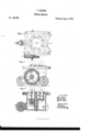
In the acconnianying drawing, which makes a part of this speciieation- Figure l is a plan view of the machine.
Figure 2 is a side elevation of the same.
Figure 3 is a vertical section at the line xx of lig. 1.
Like letters in all the figures indicate the same parts.
A is a box or case', which is provided with the molding devices.
It is mounted on wheels B B B, whereby it is easily moved to any part of the molding-floor. I prefer three wheels, in accommodation to irregularities ot' the floor.
C is a stationary follow-board, confined, by mea-ns of screws b, to the top of `the box A.
The said board has holes d, throughwhich the patterns I) pass :is the plateE on which they are secured is elevated and depressed, by means of the pinion F on the horizontalshaft G, and the vertical rack H on the hub e of said plate. y
The hub is guided bythe central post J, whose lower end is secured in the bottom fof the case A.
Ihere is aV bami-wheel, K,on one end of the pinion-shaft G, for op'ei'ating the same, to give a recipro- 'cating movement to the pinion F, for elevating and depressing the pattern-plate E.
'.lhe said wheel K has a concentric slot, g, which plays over the stationary pin L, that projects from the side hof the box A, to regulate the movements of the wheel.
Operation. The hand-wheel K is turned in the direction of the arrows until the patterns D are brought into their elevated position, as represented by dottedlines in figs.
2 and 3. A
rlhe end 1 oi' the slot g comes against the stationary pin L, and thc counter-weight K being then at thelower side of the wheel, as represented by dotted lines7 then the ask is placed on the follow-board and the sand rammed in the usual manner. i
When the ramming is completed, a reverse movement is given to the hand-wheel K, until its concentric slot g comes into the posit-ion represented in ligs. 2 and 3, the lower end of the slot g1 coming against the pin L, to hold the wheel securely.' As the wheel comes into this position, the patterns I) are withdrawn out of the sand into their lower position, represented by full lilies.
In order to make the molds formed by the patterns D of equal diameter, except at their conical ends, I form them somewhat less in diameter at-tlieir lower thaq` at their upper ends. Then, as they are withdrawn, the sand readily springs outward from them, so as to admit of the passage of their larger ends through the openings formed by the patterns. 'lhe sand springs back again when the patterns are withdrawn, but the friction of the enlarged part of the patterns on the surfaces of the molds gives sulflcient wear to the same to make them of equal size from the base of the cone to their lower end. This effect is easily accomplished by making' the back draft of the pattern only suliicient to 'give an easy spring to the sand, which possesses a certain degree oli' elasticity, even when tightly rammed.
The pat-terns D, represented in the drawing, represent such as are used in molding balls or mandrels for forming metal tubes, but it will readily be seen that patterns for other purposes may also be used with the machine.
What I claim as my invention, and desire to secure by Letters Patent, is-
l.v VThe patterns D,-c mstruoted as described, with a back draft, substantially in themanner and lor the purpose set forth.
2. They combination of the stationary pin L with the concentric slot g of the hand-wheelK, substantially as and for the purpose specified.
-In testimony that the above is my invention, I have hereunto set my hand and alixed my seal this 25th day of June, 1870.
Y THOMAS GLOVER. [L. s.]
Witnesses l THOMAS J. BEwLEv, J. C. MILLER.
Publications (1)
| Publication Number | Publication Date |
|---|---|
| US106264A true US106264A (en) | 1870-08-09 |
Family
ID=2175741
Family Applications (1)
| Application Number | Title | Priority Date | Filing Date |
|---|---|---|---|
| US106264D Expired - Lifetime US106264A (en) | Improvement in molding-machines |
Country Status (1)
| Country | Link |
|---|---|
| US (1) | US106264A (en) |
Cited By (1)
| Publication number | Priority date | Publication date | Assignee | Title |
|---|---|---|---|---|
| US20050011610A1 (en) * | 2003-07-18 | 2005-01-20 | Cobene Robert Louis | Bookbinding adhesive forming device and method |
-
0
- US US106264D patent/US106264A/en not_active Expired - Lifetime
Cited By (1)
| Publication number | Priority date | Publication date | Assignee | Title |
|---|---|---|---|---|
| US20050011610A1 (en) * | 2003-07-18 | 2005-01-20 | Cobene Robert Louis | Bookbinding adhesive forming device and method |
Similar Documents
| Publication | Publication Date | Title |
|---|---|---|
| US106264A (en) | Improvement in molding-machines | |
| US735347A (en) | Molding-machine. | |
| US491273A (en) | Molding-machine | |
| US80321A (en) | William h | |
| US1069383A (en) | Molding-machine. | |
| US198490A (en) | Improvement in molders flasks and their accessories | |
| US707535A (en) | Molding-machine. | |
| US86708A (en) | Improvement in draught-equalizers | |
| US286754A (en) | Chables o | |
| US124970A (en) | Improvement in devices for forming letters on the circumference of metal disks | |
| US1290071A (en) | Molder's flask. | |
| US193508A (en) | Improvement in match-plate moldings | |
| US432243A (en) | Molding-machine | |
| US96131A (en) | Improvement in molding and casting pipe | |
| US472312A (en) | Molding machine | |
| US195036A (en) | Improvement in molding pulleys | |
| US542038A (en) | belknap | |
| US103966A (en) | Improvement in patterns for molding stove-plates | |
| US479755A (en) | Molding-machine | |
| US1100943A (en) | Molding-flask. | |
| US820458A (en) | Cement block and post machine. | |
| US322203A (en) | Molding-machine for making molds in sand | |
| US125186A (en) | Improvement in devices for molding dovetails | |
| US501051A (en) | Lifting device | |
| US246049A (en) | Molding machine |