US1062314A - Amusement device. - Google Patents
Amusement device. Download PDFInfo
- Publication number
- US1062314A US1062314A US52324609A US1909523246A US1062314A US 1062314 A US1062314 A US 1062314A US 52324609 A US52324609 A US 52324609A US 1909523246 A US1909523246 A US 1909523246A US 1062314 A US1062314 A US 1062314A
- Authority
- US
- United States
- Prior art keywords
- track
- carrier
- pulley
- chain
- water
- Prior art date
- Legal status (The legal status is an assumption and is not a legal conclusion. Google has not performed a legal analysis and makes no representation as to the accuracy of the status listed.)
- Expired - Lifetime
Links
- XLYOFNOQVPJJNP-UHFFFAOYSA-N water Substances O XLYOFNOQVPJJNP-UHFFFAOYSA-N 0.000 description 33
- 239000000969 carrier Substances 0.000 description 20
- 230000005484 gravity Effects 0.000 description 6
- 230000007423 decrease Effects 0.000 description 4
- 238000010276 construction Methods 0.000 description 2
- 235000020289 caffè mocha Nutrition 0.000 description 1
- 239000012634 fragment Substances 0.000 description 1
- 239000003864 humus Substances 0.000 description 1
- 230000009191 jumping Effects 0.000 description 1
- 239000002244 precipitate Substances 0.000 description 1
- 230000009182 swimming Effects 0.000 description 1
Images


Classifications
-
- A—HUMAN NECESSITIES
- A63—SPORTS; GAMES; AMUSEMENTS
- A63G—MERRY-GO-ROUNDS; SWINGS; ROCKING-HORSES; CHUTES; SWITCHBACKS; SIMILAR DEVICES FOR PUBLIC AMUSEMENT
- A63G3/00—Water roundabouts, e.g. freely floating
Definitions
- the invention consists in providing tracks over a body of water and driving cars or devices over the tracks in operative relation to the water.
- the tracks are so arranged that the cars recede from and approach the water.
- the carriers for the cars and devices are driven on the tracks by endless chains. Suitable means of approach are also provided.
- Figure 1 shows a plan view of the device.
- Fig. 2 is an end view of the device.
- Fig. 3 is a side elevation of the entrance and the device.
- Fig. 4 is an end view of the device at the end opposite the entrance and opposite the end shown in Fig. 2.
- Fig. 5 is a view similar to Fig. 3 but showing only one track.
- Fig. 5 shows a side elevation of a fragment of the device at the end having the motor.
- Fig. 6 is a side elevation of the boat forming one of the cars with its carrier.
- Fig. 7 is an end elevation of the same.
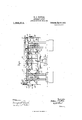
- Fig. 10 is a side elevation of one of the driving pulleys part being broken away to show construction.
- Fig. 11 is a vertical section of the driving wheel.
- 'Fig. 12 is a side elevation of wheel car with its carrier.
- Fig. 13 is an end elevation of the same.
- Fig. 14 shows an enlarged view of one of the carriers with its support, the view being at the end of, the carrier.
- Fig. 15 is a side elevation of the same parts.
- Figs. 16, 17 and 18 show diflerent forms of swings on some of the carriers.
- 1 marks the body of water, 2 the foundation or base, 3 the uprights forming the frame, 8 bridge work carried by the uprights, said bridgework carrying several tracks.
- the boat track being formed of the double rail 4.
- This track is in the general form of a loo-p making a complete circuit.
- a platform 5 is provided adjacent to the paths of cars.
- the cars as they are loaded are supported on the loop 6 of the track, passing from this on to the practically straight part 7, and from said loop by the loop 8 to the return track 7
- This track is arranged between the series of uprights 3 andis suspended from the bridgework 3 by the hangers 3
- Said track is formed with a series of declines 9 and inclines 10 approaching and receding from the water and so positioned that the car carried by the carrier on the track at the bottom of each decline strikes the water.
- These variations extend throughout the straight part of the track.
- At the end of each straight part the track is sufficiently elevated so that the loop 8 has sufficient declination to carry the car around the loop by gravity.
- the loop 6 has also some slant for the same purpose, although this being the starting end, it should have very little if any.
- the cars on the track 4 are driven by the chain 11, the power being supplied by a motor 12.
- a gear 13 is fixed on the driving shaft of the motor and meshes the gear 14.
- the gear 14 is fixed on a'shaft 14L carried in bearings 14*.
- a sprocket 15 is fixed on the shaft 14* and the drive chain 11 passes over this sprocket. It passes from this sprocket around a pulley 15*, over a pulley 16, across the end of the structure and over a pulley 17. In this reach across the structure the chain is out of position to engage the car or carrier. From the pulley 17 the chain passes over the pulley 18, then under the pulleys 20, over the pulleys 19 and under the straight part of the track 7*.
- the chain passes under the pulley 21, over the pulley 22 (see Fig. l), across the end of the structure, out of the path of the track, over the the starting end of the machine the chain is carried over the pulley 24*, under the pulley 24 under the pulley 24 and over the pulley 24, from which it passes to the drive pulley 15.
- the apex 25 of the incline is reached before the chain passes to the pulley 19, so that the carrier is carried by the chain over the apex.
- the chain 11 over those parts of the track forming the declines, is out of position to engage the carriers and the pulleys 20 are slightly up the incline so that the carrier has started by its momentum when it is caught by the carrier.
- the bottoms of the inclines 26 are slightly in front of the pulleys 20 as shown in Fig. 5.
- the carrier for the track 4 is shown in detail in Figs. 6 and 7.
- the carrier 27 is provided with the wheels 28, the wheels being journaled on the axles 29, the carrier being provided with axle extensions 30 for this purpose.
- An engaging lug 31 extends parallel with the carrier and is provided with teeth 32 for engaging driving chain.
- the arms 33 extend downwardly from the carrier and support the boat 34.
- Figs. 8 and 9 The details of the driving chain are shown in Figs. 8 and 9. It is formed of an ordinary link 11, but on each alternate link there is arranged the disk shoulder 11".
- FIGs. 10 and 11 the details of one of the driving pulleys are shown.
- the flat links travel on the surface 35 of this pulley.
- a groove 36 receivesthe edgewise links and the disks 11 are received by the pockets 37, the walls of these pockets forming the teeth of the sprocket.
- a track 38 is arranged outside of the track 4, and is preferably approximately parallel to it and the carriers upon it are preferably driven in the opposite direction. This track is supported from the uprights 3 and the bridge work 3 by means of brackets 39. Said track is loaded from a platform 40 to which a stairway 41 leads.
- the track passes from the platform by way of the end loop 42 by gravity, then drops down the incline 43 into position to bring its carrier into proper relation to the water, and then extends along the part 44 practically parallel to the water to near the opposite end of the device where it is raised up sufficiently to carry it around the loop 46 by gravity.
- the decline 47 on the opposite side of the device again drops the carrier down to near the-water and the track then extends along the part 48 approximately parallel to the water to the starting in of the decline to the incline 49', which brings it back to the starting point 50.
- the carrier on the track 38 is driven from the motor 12 by means of a chain similar to the chain 11.
- a sprocket 51 is fixed on the shaft 14
- the chain 52 extends from the sprocket 51 tothe sprocket 53.
- the sprocket 53 is fixed on the shaft 54. These shafts are provided with suitable bearings on the frame.
- Chain 55 is driven by sprocket 56 over which the chain passes.
- Chain 55 over the track 38 is driven in the opposite direction from the chain 11.
- Chain 55 passes from the pulley 56 under the pulley 57, said chain being carried out of position to engage the carrier on the portion of the track 43, but with such relation to the track 44 as to engage the carrier and take it along with it.
- the chain then passes under the pulley 58, over the pulley 59 across the top of the machine, over the pulley 60, under the pulley 61 into position to engage carrier on the part 48, under the pulley 62, over the pulley 63 and over the pulley 64 to the starting point.
- a carrier for the track 38 is shown in detail in Figs. 12 and 13.
- Carrier 65 is provided with the pulleys 66 journaled on the axles 67, and teeth for engaging the chain extend down to form a hanger 69 across a wheel 70 on-a shaft 71 terminating in a U 72 at the bottom of the carrier.
- the pulley 70 prevents the wheel 66 from jumping the track.
- the side wheel 69 takes any side thrust there may be.
- the car carried by this carrier is of peculiar construction, and comprises a wheel driven by its movement through the water so as to elevate water over the seat carried by the car.
- a shaft 74 is fixed in the bottom of the hanger 69 and carries the links 75. These links 75 are se cured to a plate 76.
- the hangers 77 are suspended from the plate 76 and carry the axle 78.
- the axle has a downward bend 79 at the center in which the seat 80 is arranged.
- the wheel 81 is journaled on the axle and has a series of paddles 82 which carry the cups 83.
- the surface of the wheel has the openings 84 through which the water elevated by the cups 83 is thrown into the interior of the wheel.
- a shield 86 is provided which may be thrown into the path of the water by the operator if desired.
- This seat is journaled on the axle 78 and swings on it. I prefer to provide the deflectors 85 on the interior of the wheel to deflect the water so as to more readily precipitate it over the seat.
- central track 87 is arranged within the track 4 and forms a complete circuit, is preferably level with the water except at the ends where it is inclined so that the carrier may be moved around the ends by gravity. It is supported by the brackets 88 extending from the uprights 3. It is provided with a loop 89 at the starting end which has very little inclination. The straight portions 90 and 92 on the loop 91, are sufficiently inclined to assure the car moving around the loop by gravity.
- the carrier 93 for track 87 is similar to the carrier for the track 38. Said carrier is shown in large view and detail in Figs. 14: and 15.
- the carrier 93 has the axles 94 on the center of which the wheels 95 are journaled.
- the lug 96 at the top of the carrier has the teeth 96 which are adapted to engage the drive chain.
- the hanger 97 extends downwardly from the carrier and terminates in the U 98.
- the axle 99 is arranged in the U 98 and carries a wheel 100 single loop 107
- the carriers 93 are driven by the chain 108 from the motor 12.
- the chain 108 is driven from the pulley 109. This is fixed on the shaft 110.
- a pulley 111 is fixed on this shaft.
- a chain 112 extends from the pulley 111 to the pulley 113 on the shaft 14?. By following the movements of these various pulleys it will be observed that the chain 108 is driven in the opposite directionfrom the chain 111. The chain passes by reach 11 1 from the pulley 115, then by a reach 116 over a pulley 117, the reach 116 being near the top of the machine to get it.
- an amusement device the combination with a body of water; of a plurality of tracks making complete circuits; carriers on said tracks; means for driving said carriers, said means being deflected at the point in the track to permit entrance into and egress from the carriers.
- a first track making a complete circuit in the form of a loop above the water approaching and receding from the water along the sides of the loop, a decline at the end of the loop; carriers suspended from said track and having a boat thereon brought into engagement with the water at the bottom of the declines; means for driving the said carrier adapted to engage said carrier on the inclines and disengage therefrom on the declines; a second track making a complete circuit outside the first track and having a carrier thereon, having a wheel adapted to be rotated by the water and to throw water on the occupant of the carrier; means for driving the carrier on the second track; a third track within the first track making a complete circuit in the form of a loop; a carrier on said track having devices for carrying an occupant in a swimming position in the water; means for driving said third said tracks; and means for driving said 10 7 carriers.
Landscapes
- Management, Administration, Business Operations System, And Electronic Commerce (AREA)
Description
wwwmw W. P. WITTIUH. I AMUSEMENT DEVICE. APPLICATION FILED 00T.18, 1 909.
1,0623 14. Patented May 20, 1913.
8 SHEETS-SHEET 1.
. Svwemtoz Mocha COLUMBIA PLANOGRAPH C0,,WASHINOTON, D. C.
w. F. WITTIOH. AMUSEMENT DEVICE. APPLICATION FILED OUT-18, 1909- 8 SHEETS-SHEET Z.
wn humus I I aZ%/ FIOLUMBIA PLANOURAFH C O., WASHINGTON, D. C.
Patented May 20, 1913.
w. P. WITTIOH.
AMUSEMENT DEVICE.
' APPLICATION FILED-00118, 1000.
1,062,? 14. v mm m 20, 1913.
8 SEEBTFSHEET 3.
W. P. WITTIGH.
AMUSEMENT DEVICE.
APPLIOATION FILED 0053.18, 1909.
1,062,? 14. Patented May 20, 1913..
8 SHEETS-SHEET 4.
COLUMBIA PLANOGRAPH 0" WASHINGTON. D. C.
W. F. WITTICH.
AMUSEMENT DEVIGE.-
APPLICATION FILED 0011s, 1909.
Patented May 20, 1913.
a SHEETS-SHEET a.
I i I I I I WW W. F. WITTIOH.
AMUSEMENT DEVICE.
APPLICATION FILED 0OT.18, 1909.
1,0623 14. Patented May 20, 1913.
8 SHEETS-SHEET 6.
COLUMBIA PLANOGHAPH CO1. WASHINGTON, D; C-'
W. F. WITTIOH. I
AMUSEMENT DEVICE.
APPLICATION FILED 0011s, 1909,
1,062,3 14;. Patented May 20, 1913.
V a SHEETS-SHEET I.
' 32. g 1 4, "4, W lif: :rZK Lf NTHZI K 3. 7 3 al Q Emma/box W. F. WITTIGH.
AMUSEMENT DEVICE. APPLICATION FILE 0011s, 1909.
1,062,314. Patented May 20,1913.
8 SHEETS-SHEET 8.
- $7M. 'mfmww I i I w J COLUMBIA PLANOORAPH CO, WASHINGTON. D. C.
hurrah srarns rarest @FFTCE.
WILLIAM F. WITTICH, OF. ERIE, PENNSYLVANIA.
AMUSEMENT DEVICE.
To all whom it may concern:
Be it known that I, WILLIAM F. VVITTICH, a citizen of the United States, residing at Erie, in the county of Erie and State of Pennsylvania, have invented new and useful Improvements in Amusement Devices, of which the following is a specification.
In a general way the invention consists in providing tracks over a body of water and driving cars or devices over the tracks in operative relation to the water. Preferably the tracks are so arranged that the cars recede from and approach the water. The carriers for the cars and devices are driven on the tracks by endless chains. Suitable means of approach are also provided.
Various details of the invention will appear in the specification and claims.
The invention is illustrated in the accompanying drawings as follows:
Figure 1 shows a plan view of the device. Fig. 2 is an end view of the device. Fig. 3 is a side elevation of the entrance and the device. Fig. 4 is an end view of the device at the end opposite the entrance and opposite the end shown in Fig. 2. Fig. 5 is a view similar to Fig. 3 but showing only one track. Fig. 5 shows a side elevation of a fragment of the device at the end having the motor. Fig. 6 is a side elevation of the boat forming one of the cars with its carrier. Fig. 7 is an end elevation of the same. Fig. 8 is an enlarged plan view of the driving chain. 9 is an end view of the same. Fig. 10 is a side elevation of one of the driving pulleys part being broken away to show construction. Fig. 11 is a vertical section of the driving wheel. 'Fig. 12 is a side elevation of wheel car with its carrier. Fig. 13 is an end elevation of the same. Fig. 14 shows an enlarged view of one of the carriers with its support, the view being at the end of, the carrier. Fig. 15 is a side elevation of the same parts. Figs. 16, 17 and 18 show diflerent forms of swings on some of the carriers.
1 marks the body of water, 2 the foundation or base, 3 the uprights forming the frame, 8 bridge work carried by the uprights, said bridgework carrying several tracks.
Specification ofLetters Patent.
Patented May 20, 1913.
Application filed 0ctober18, 1909. Serial No. 523,246.
In the structure shown there are three tracks, the boat track being formed of the double rail 4. This track is in the general form of a loo-p making a complete circuit. A platform 5 is provided adjacent to the paths of cars. The cars as they are loaded are supported on the loop 6 of the track, passing from this on to the practically straight part 7, and from said loop by the loop 8 to the return track 7 This track is arranged between the series of uprights 3 andis suspended from the bridgework 3 by the hangers 3 Said track is formed with a series of declines 9 and inclines 10 approaching and receding from the water and so positioned that the car carried by the carrier on the track at the bottom of each decline strikes the water. These variations extend throughout the straight part of the track. At the end of each straight part the track is sufficiently elevated so that the loop 8 has sufficient declination to carry the car around the loop by gravity. The loop 6 has also some slant for the same purpose, although this being the starting end, it should have very little if any.
The cars on the track 4 are driven by the chain 11, the power being supplied by a motor 12. A gear 13 is fixed on the driving shaft of the motor and meshes the gear 14. The gear 14 is fixed on a'shaft 14L carried in bearings 14*. A sprocket 15 is fixed on the shaft 14* and the drive chain 11 passes over this sprocket. It passes from this sprocket around a pulley 15*, over a pulley 16, across the end of the structure and over a pulley 17. In this reach across the structure the chain is out of position to engage the car or carrier. From the pulley 17 the chain passes over the pulley 18, then under the pulleys 20, over the pulleys 19 and under the straight part of the track 7*.
At the end of the straight part the chain passes under the pulley 21, over the pulley 22 (see Fig. l), across the end of the structure, out of the path of the track, over the the starting end of the machine the chain is carried over the pulley 24*, under the pulley 24 under the pulley 24 and over the pulley 24, from which it passes to the drive pulley 15.
It will be noted that the apex 25 of the incline is reached before the chain passes to the pulley 19, so that the carrier is carried by the chain over the apex. The chain 11 over those parts of the track forming the declines, is out of position to engage the carriers and the pulleys 20 are slightly up the incline so that the carrier has started by its momentum when it is caught by the carrier. The bottoms of the inclines 26 are slightly in front of the pulleys 20 as shown in Fig. 5.
The carrier for the track 4 is shown in detail in Figs. 6 and 7. The carrier 27 is provided with the wheels 28, the wheels being journaled on the axles 29, the carrier being provided with axle extensions 30 for this purpose. An engaging lug 31 extends parallel with the carrier and is provided with teeth 32 for engaging driving chain. The arms 33 extend downwardly from the carrier and support the boat 34.
The details of the driving chain are shown in Figs. 8 and 9. It is formed of an ordinary link 11, but on each alternate link there is arranged the disk shoulder 11".
In Figs. 10 and 11 the details of one of the driving pulleys are shown. The flat links travel on the surface 35 of this pulley. A groove 36 receivesthe edgewise links and the disks 11 are received by the pockets 37, the walls of these pockets forming the teeth of the sprocket. It will be observed with this driving chain may be carried over pulleys having their axes at right angles to each other. For this reason it 1s peculiarly adapted for the use here shown. A track 38 is arranged outside of the track 4, and is preferably approximately parallel to it and the carriers upon it are preferably driven in the opposite direction. This track is supported from the uprights 3 and the bridge work 3 by means of brackets 39. Said track is loaded from a platform 40 to which a stairway 41 leads. The track passes from the platform by way of the end loop 42 by gravity, then drops down the incline 43 into position to bring its carrier into proper relation to the water, and then extends along the part 44 practically parallel to the water to near the opposite end of the device where it is raised up sufficiently to carry it around the loop 46 by gravity. The decline 47 on the opposite side of the device again drops the carrier down to near the-water and the track then extends along the part 48 approximately parallel to the water to the starting in of the decline to the incline 49', which brings it back to the starting point 50.
The carrier on the track 38 is driven from the motor 12 by means of a chain similar to the chain 11. A sprocket 51 is fixed on the shaft 14 The chain 52 extends from the sprocket 51 tothe sprocket 53. The sprocket 53 is fixed on the shaft 54. These shafts are provided with suitable bearings on the frame. Chain 55 is driven by sprocket 56 over which the chain passes.
Following the pulleys in their course, it will be noted that the chain 55 over the track 38 is driven in the opposite direction from the chain 11. Chain 55 passes from the pulley 56 under the pulley 57, said chain being carried out of position to engage the carrier on the portion of the track 43, but with such relation to the track 44 as to engage the carrier and take it along with it. The chain then passes under the pulley 58, over the pulley 59 across the top of the machine, over the pulley 60, under the pulley 61 into position to engage carrier on the part 48, under the pulley 62, over the pulley 63 and over the pulley 64 to the starting point.
A carrier for the track 38 is shown in detail in Figs. 12 and 13. Carrier 65 is provided with the pulleys 66 journaled on the axles 67, and teeth for engaging the chain extend down to form a hanger 69 across a wheel 70 on-a shaft 71 terminating in a U 72 at the bottom of the carrier. The pulley 70 prevents the wheel 66 from jumping the track. The side wheel 69 takes any side thrust there may be. The car carried by this carrier is of peculiar construction, and comprises a wheel driven by its movement through the water so as to elevate water over the seat carried by the car. A shaft 74 is fixed in the bottom of the hanger 69 and carries the links 75. These links 75 are se cured to a plate 76. The hangers 77 are suspended from the plate 76 and carry the axle 78. The axle has a downward bend 79 at the center in which the seat 80 is arranged. The wheel 81 is journaled on the axle and has a series of paddles 82 which carry the cups 83. The surface of the wheel has the openings 84 through which the water elevated by the cups 83 is thrown into the interior of the wheel. As the car formed by this wheel is carried along the portions of the track 48 and 44 the p1ates42 are in the water and their resistance causes the wheel to rotate, carrying up with it water in the cups 83 which is deposited from the top through the openings 84'on to the seat 80. A shield 86 is provided which may be thrown into the path of the water by the operator if desired. This seat is journaled on the axle 78 and swings on it. I prefer to provide the deflectors 85 on the interior of the wheel to deflect the water so as to more readily precipitate it over the seat. central track 87 is arranged within the track 4 and forms a complete circuit, is preferably level with the water except at the ends where it is inclined so that the carrier may be moved around the ends by gravity. It is supported by the brackets 88 extending from the uprights 3. It is provided with a loop 89 at the starting end which has very little inclination. The straight portions 90 and 92 on the loop 91, are sufficiently inclined to assure the car moving around the loop by gravity.
The carrier 93 for track 87 is similar to the carrier for the track 38. Said carrier is shown in large view and detail in Figs. 14: and 15. The carrier 93 has the axles 94 on the center of which the wheels 95 are journaled. The lug 96 at the top of the carrier has the teeth 96 which are adapted to engage the drive chain. The hanger 97 extends downwardly from the carrier and terminates in the U 98. The axle 99 is arranged in the U 98 and carries a wheel 100 single loop 107 The carriers 93 are driven by the chain 108 from the motor 12. The chain 108 is driven from the pulley 109. This is fixed on the shaft 110. A pulley 111 is fixed on this shaft. A chain 112 extends from the pulley 111 to the pulley 113 on the shaft 14?. By following the movements of these various pulleys it will be observed that the chain 108 is driven in the opposite directionfrom the chain 111. The chain passes by reach 11 1 from the pulley 115, then by a reach 116 over a pulley 117, the reach 116 being near the top of the machine to get it. out of the way for the entrance to the track 87, it passes then by reach 118 over pulley 119, then along the portion of the track 92 by a reach 120, under a pulley 121 then over the pulley 122 by a reach 123, over the pulley 121, under the pulley 125, then with reach 126 over the track 90 to the pulley 109, The chain while passing over reaches 120 and 126 is in a position to engage the carrier on the track. It will be observed that the uprights in their double relation readily provide the double track having the greatest swing whereas the uprights provide means whereby two other tracks may be supported with the carriers overhanging the tracks. It is also desirable to move the carriers in opposite directions so that the occupants meet. The water in combination with the device not only aifords an additional feature for the device, but also in places where this is commonly constructed supplies ample room for its erection.
What I claim as new is:
1. In an amusement device the combination with a body of water; of a plurality of tracks making complete circuits; carriers on said tracks; means for driving said carriers, said means being deflected at the point in the track to permit entrance into and egress from the carriers.
2. In an amusement device the combination with a body of water; of a track arranged above the water making a complete circuit; a carrier 011 the track; means for driving the carrier, said means being deflected out of the path of the carrier to permit the entrance to and egress from the carrier.
3. In an amusement device the combination with a body of water; of a plurality of tracks making complete circuits in the form of loop-above the water, said tracks being declined at the end of the loop to move the carrier around the ends of the loo; by gravity; carriers on said tracks; means for driving said carriers, said means being deflected out of the path of the carriers at the ends of the loops.
4. In an amusement device the combination with a body of water; of a plurality of tracks making complete circuits in the form of a loop above the water and having inclines at the end of the loop for moving a carrier around the end of the loop; carriers on said tracks; means for driving said carriers, said means being deflected out of the paths of the carriers at the ends of the loo-p and out of the path of carriers on the other track.
5. In an amusement device the combination with a body of water; of a first track making a complete circuit in the form of a loop above the water approaching and receding from the water along the sides of the loop, a decline at the end of the loop; carriers suspended from said track and having a boat thereon brought into engagement with the water at the bottom of the declines; means for driving the said carrier adapted to engage said carrier on the inclines and disengage therefrom on the declines; a second track making a complete circuit outside the first track and having a carrier thereon, having a wheel adapted to be rotated by the water and to throw water on the occupant of the carrier; means for driving the carrier on the second track; a third track within the first track making a complete circuit in the form of a loop; a carrier on said track having devices for carrying an occupant in a swimming position in the water; means for driving said third said tracks; and means for driving said 10 7 carriers.
In testimony whereof, I have hereunto set my hand in the presence of two subscribing witnesses.
WILLIAM F. WITTICH. Witnesses WV. J. YOUNG, J ESSIE RHODES.
Copies of this patent may be obtained for five cents each, by addressing the Commissioner of Patents, Washington, D. G.
Priority Applications (1)
| Application Number | Priority Date | Filing Date | Title |
|---|---|---|---|
| US52324609A US1062314A (en) | 1909-10-18 | 1909-10-18 | Amusement device. |
Applications Claiming Priority (1)
| Application Number | Priority Date | Filing Date | Title |
|---|---|---|---|
| US52324609A US1062314A (en) | 1909-10-18 | 1909-10-18 | Amusement device. |
Publications (1)
| Publication Number | Publication Date |
|---|---|
| US1062314A true US1062314A (en) | 1913-05-20 |
Family
ID=3130560
Family Applications (1)
| Application Number | Title | Priority Date | Filing Date |
|---|---|---|---|
| US52324609A Expired - Lifetime US1062314A (en) | 1909-10-18 | 1909-10-18 | Amusement device. |
Country Status (1)
| Country | Link |
|---|---|
| US (1) | US1062314A (en) |
Cited By (1)
| Publication number | Priority date | Publication date | Assignee | Title |
|---|---|---|---|---|
| US5664501A (en) * | 1995-04-06 | 1997-09-09 | Ford Motor Company | Power and free conveying system |
-
1909
- 1909-10-18 US US52324609A patent/US1062314A/en not_active Expired - Lifetime
Cited By (1)
| Publication number | Priority date | Publication date | Assignee | Title |
|---|---|---|---|---|
| US5664501A (en) * | 1995-04-06 | 1997-09-09 | Ford Motor Company | Power and free conveying system |
Similar Documents
| Publication | Publication Date | Title |
|---|---|---|
| US760503A (en) | Wonderland scenic waterway. | |
| US792422A (en) | Pleasure-railway. | |
| US1062314A (en) | Amusement device. | |
| US719751A (en) | Spiral elevator. | |
| US786117A (en) | Observation-train. | |
| US1083308A (en) | Amusement apparatus. | |
| US946200A (en) | Amusement apparatus. | |
| US793471A (en) | Amusement device. | |
| US1000742A (en) | Pleasure-railway. | |
| US867432A (en) | Pleasure-railway. | |
| US946730A (en) | Amusement apparatus. | |
| US777497A (en) | Scenic railway. | |
| US750717A (en) | Rotary pleasure-tower | |
| US286895A (en) | bolph | |
| US955217A (en) | Inclined railway. | |
| US1300555A (en) | Amusement aerial railway. | |
| US678243A (en) | Amusement-railway. | |
| US1053595A (en) | Roundabout. | |
| US723559A (en) | Pleasure-railway. | |
| US852184A (en) | Pleasure-railway. | |
| US687071A (en) | Mechanical toy. | |
| US714778A (en) | Current-motor. | |
| US838594A (en) | Means for elevating cars, &c. | |
| US1462179A (en) | Game apparatus or amusement device | |
| US348798A (en) | Pleasure cable railway |