US723559A - Pleasure-railway. - Google Patents
Pleasure-railway. Download PDFInfo
- Publication number
- US723559A US723559A US10947802A US1902109478A US723559A US 723559 A US723559 A US 723559A US 10947802 A US10947802 A US 10947802A US 1902109478 A US1902109478 A US 1902109478A US 723559 A US723559 A US 723559A
- Authority
- US
- United States
- Prior art keywords
- point
- railway
- rails
- car
- course
- Prior art date
- Legal status (The legal status is an assumption and is not a legal conclusion. Google has not performed a legal analysis and makes no representation as to the accuracy of the status listed.)
- Expired - Lifetime
Links
Images
Classifications
-
- A—HUMAN NECESSITIES
- A63—SPORTS; GAMES; AMUSEMENTS
- A63G—MERRY-GO-ROUNDS; SWINGS; ROCKING-HORSES; CHUTES; SWITCHBACKS; SIMILAR DEVICES FOR PUBLIC AMUSEMENT
- A63G21/00—Chutes; Helter-skelters
Definitions
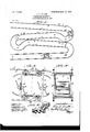
- My invention relates to that class of railways designed to furnish amusement, the apparatus comprising two series of tracks that extend from an elevation first in one direction and then in a reverse direction and alternating throughout their extent in similar manner to a point at a lower elevation and a car adapted to traverse said tracks and provided with swinging seats that constantly retain their uprightness throughout the course of the apparatus.
- Figure I is a side view illustrating my railway with the cars shown in varying positions therein. tion of portions of the railway-tracks and a car situated between them.
- Fig. III is avertical transverse section taken on line 111' III
- Fig. II is a perspective view showing in detail one of the swinging track-rail sections and the means by which it is supported.
- 1 and 2 designate pairs of track-rails that extend on parallel lines with each other, first in a downwardlyinclined direction to the point A, (see Fig. 1,) thence downwardly in a curving dip to the point B, thence in an up-.
- the rails 1 again constituting the trackrails and the rails 2 again constituting the guide-rails.
- the rails extend in a downwardly-inclined direction the reverse of the course from the point C to D to the point G and again dip from the point If to the point I, their course being in a di rection the reverse of that from the point F to G.
- the circuitous course of the railway may be continued in a manner similar to that described from the point I, or such circuitous course may be terminated and the cars be conducted in a straight course to a point of stoppage.
- ' 10 represents swinging seats that are pivoted at 11 to the posts or frames 9, so as to be capable of complete rotation within the cars. It will be seen that by swingingly mounting the seats they may turn on their pivots to accommodate themselves to the direction of travel of the car irrespective of its course in straight, dipping,or curving lines, so that the occupants of the seats will always remain in upright positions throughout the travel of the car in its circuitous transit through the railway.
- a pleasure-railway comprising a pair of tracks, extending first in one direction, then dipping downwardly and extending in a direction the reverse of the initial course, each of which constitutes the track-rails during portions of the circuit of the railway,and throughout other portions constituting overhead guide-rails.
- a pleasure-railway comprising a pair of tracks extending first in one direction, then dipping downwardly and extending in a direction the reverse of its initial course, and again dipping downwardly and extending in a direction similar to its initial course, each of which constitutes the head-rails during portions of the circuit of the railway,and throughout other portions constituting overhead guide-rails, substantially as described.
- a pleasure railway comprising a pair of tracks extending first in one direction, then dipping downwardly and extending in a direction the reverse of its initial course, then dipping downwardly and extending in a direction similar to its initial course, and then dipping downwardly and extending again in a direction the reverse of its initial course, substantially as described.
- a pleasure-railway comprising a pair of tracks extending first in one direction then dipping downwardly and upwardly and then downwardly in an inclined direction the reverse of its initial course, substantially as described.
- a pleasu re-rail way comprising a circuitous track extending in alternate directions in a vertical tier, and having dips at the junction of its alternate courses, substantially as described.
- a pleasure-railway comprising a pair of circuitous tracks provided with dips, and overhead swinging rail-sections mounted in said tracks at the approach to said dips, substantially as described.
Description
No. 723,559. PATENTED MAR. 24,'-1903. J. T. TRUITT. PLEASURE RAILWAY.
APPLIOA TION FILED MAY 29, 1902.
10 MODEL.
UNITED STATES PATENT GFFICE.
JOHN T. ,TRUITT, OF ST. LOUIS, MISSOURI.
-PLEASU RE-RAILWAY.
SPECIFICATION forming part of Letters Patent No. 723,559, dated March 24, 1903.
Application filed May 29, 1902.
To all whom it may concern: I
Be it known that I, JOHN T. TRUITT, a citizen of the United States, residing in the city of St. Louis, in the State of Missouri, haveinvented certain new and useful Improvements in Pleasure-Railways, of which the following is a full, clear, and exact description, reference being had to the accompanying drawings, forming part of this specification.
My invention relates to that class of railways designed to furnish amusement, the apparatus comprising two series of tracks that extend from an elevation first in one direction and then in a reverse direction and alternating throughout their extent in similar manner to a point at a lower elevation and a car adapted to traverse said tracks and provided with swinging seats that constantly retain their uprightness throughout the course of the apparatus.
My invention consists in features of novelty hereinafter fully described, and pointedout in the claims.
Figure I is a side view illustrating my railway with the cars shown in varying positions therein. tion of portions of the railway-tracks and a car situated between them.- Fig. III is avertical transverse section taken on line 111' III, Fig. II. Fig. IV is a perspective view showing in detail one of the swinging track-rail sections and the means by which it is supported.
1 and 2 designate pairs of track-rails that extend on parallel lines with each other, first in a downwardlyinclined direction to the point A, (see Fig. 1,) thence downwardly in a curving dip to the point B, thence in an up-.
wardly-inclined direction-to the point C in a direction the reverse of the course to the point A, the rails 1 constituting the trackrails for a car as it travels to the point A and the rails 2 constituting overhead guide-rails to said point A. As the car, to be hereinafter described, dips down in its travel to the point B it is guided between the rails 1 and 2, and on the approach to the point B the rails 2 become the track-rails and the rails 1 at this point above them 'become the guiderails for the car. The car proceeds on its course from the point B upwardly to the point C, thence downwardly in an inclined Fig. II is an enlarged side eleva-.
Serial miioatvs. (No model.)
direction to the point D, where the trackrails again dip to the point E and ascend to the point F, the rails 1 again constituting the trackrails and the rails 2 again constituting the guide-rails. From the point F the rails extend in a downwardly-inclined direction the reverse of the course from the point C to D to the point G and again dip from the point If to the point I, their course being in a di rection the reverse of that from the point F to G. The circuitous course of the railway may be continued in a manner similar to that described from the point I, or such circuitous course may be terminated and the cars be conducted in a straight course to a point of stoppage.
In order to provide for the unequal travel of the car-wheels at the approach to the dips from A to B, &c., and so that the car traveling in the railway will approach the dips correctly and without binding action, I introduce swinging rail-sections 3 at the approach to said dips, the sections being pivoted at 4 to therails overhead atthe point of their introduction and having their opposite ends loosely united to the rails at the opposite sides of the gap which they close, so that they may swing vertically when struck by the wheels of the car, and therefore accommodate themselves to both the foremost and rearmost wheels at the top of the car to maintain the engagement of the wheels with the overhead track irrespective of the varying arcs in which they move on the approach to the dipping portions of the railway. I have shown the swinging ends of the rail-sections 3 suspended from slotted links 5; but any other desirable means of loosely supporting them may be utilized.
6 designates a car adapted to travel in the railway, theoar being so designed as to be suitable for travel invertedly in the railway, the car being equipped with two sets of wheels 7 and 8, either of which is adapted to travel upon the rails 1 or 2 or to bear against said rails when they constitute the guides for the direction of the car. The car isprovided with posts or frames 9.
' 10 represents swinging seats that are pivoted at 11 to the posts or frames 9, so as to be capable of complete rotation within the cars. It will be seen that by swingingly mounting the seats they may turn on their pivots to accommodate themselves to the direction of travel of the car irrespective of its course in straight, dipping,or curving lines, so that the occupants of the seats will always remain in upright positions throughout the travel of the car in its circuitous transit through the railway.
I claim as my invention- 1. A pleasure-railway comprising a pair of tracks, extending first in one direction, then dipping downwardly and extending in a direction the reverse of the initial course, each of which constitutes the track-rails during portions of the circuit of the railway,and throughout other portions constituting overhead guide-rails.
2. A pleasure-railway comprising a pair of tracks extending first in one direction, then dipping downwardly and extending in a direction the reverse of its initial course, and again dipping downwardly and extending in a direction similar to its initial course, each of which constitutes the head-rails during portions of the circuit of the railway,and throughout other portions constituting overhead guide-rails, substantially as described.
3. A pleasure railway comprising a pair of tracks extending first in one direction, then dipping downwardly and extending in a direction the reverse of its initial course, then dipping downwardly and extending in a direction similar to its initial course, and then dipping downwardly and extending again in a direction the reverse of its initial course, substantially as described.
4. A pleasure-railway comprising a pair of tracks extending first in one direction then dipping downwardly and upwardly and then downwardly in an inclined direction the reverse of its initial course, substantially as described.
5. A pleasu re-rail way comprising a circuitous track extending in alternate directions in a vertical tier, and having dips at the junction of its alternate courses, substantially as described.
6. A pleasure-railway comprising a pair of circuitous tracks provided with dips, and overhead swinging rail-sections mounted in said tracks at the approach to said dips, substantially as described.
JOHN T. TRUITT.
In presence of- E. S. KNIGHT, M. P. SMITH.
Priority Applications (1)
| Application Number | Priority Date | Filing Date | Title |
|---|---|---|---|
| US10947802A US723559A (en) | 1902-05-29 | 1902-05-29 | Pleasure-railway. |
Applications Claiming Priority (1)
| Application Number | Priority Date | Filing Date | Title |
|---|---|---|---|
| US10947802A US723559A (en) | 1902-05-29 | 1902-05-29 | Pleasure-railway. |
Publications (1)
| Publication Number | Publication Date |
|---|---|
| US723559A true US723559A (en) | 1903-03-24 |
Family
ID=2792072
Family Applications (1)
| Application Number | Title | Priority Date | Filing Date |
|---|---|---|---|
| US10947802A Expired - Lifetime US723559A (en) | 1902-05-29 | 1902-05-29 | Pleasure-railway. |
Country Status (1)
| Country | Link |
|---|---|
| US (1) | US723559A (en) |
-
1902
- 1902-05-29 US US10947802A patent/US723559A/en not_active Expired - Lifetime
Similar Documents
| Publication | Publication Date | Title |
|---|---|---|
| US723559A (en) | Pleasure-railway. | |
| US1101630A (en) | Amusement apparatus. | |
| US1823010A (en) | Amusement ride | |
| US468110A (en) | Railroad | |
| US678243A (en) | Amusement-railway. | |
| US355604A (en) | Frank b | |
| USRE15244E (en) | Amusement apparatus | |
| US786117A (en) | Observation-train. | |
| US601296A (en) | Of car wheels upon grades | |
| US475102A (en) | Tramway | |
| US549701A (en) | Thomas e | |
| US788322A (en) | Railroad system. | |
| US318360A (en) | Half to john f | |
| US395921A (en) | Robert f | |
| US562141A (en) | mceleoy | |
| US731292A (en) | Railway construction. | |
| US406302A (en) | pendleton | |
| US746467A (en) | Pleasure-railway. | |
| US421820A (en) | Rail for elevated ways | |
| US562211A (en) | boynton | |
| US485286A (en) | Car-truck | |
| US230999A (en) | Railway track and car | |
| US867506A (en) | Amusement apparatus. | |
| US602239A (en) | de palaoio | |
| US860736A (en) | Aerial tramway. |