US10622644B2 - Process for treating a bipolar plate for a fuel cell - Google Patents
Process for treating a bipolar plate for a fuel cell Download PDFInfo
- Publication number
- US10622644B2 US10622644B2 US15/572,885 US201615572885A US10622644B2 US 10622644 B2 US10622644 B2 US 10622644B2 US 201615572885 A US201615572885 A US 201615572885A US 10622644 B2 US10622644 B2 US 10622644B2
- Authority
- US
- United States
- Prior art keywords
- bipolar plate
- parallel
- rows
- straightening rollers
- rollers
- Prior art date
- Legal status (The legal status is an assumption and is not a legal conclusion. Google has not performed a legal analysis and makes no representation as to the accuracy of the status listed.)
- Active, expires
Links
- 239000000446 fuel Substances 0.000 title claims abstract description 16
- 238000000034 method Methods 0.000 title claims abstract description 15
- 239000002184 metal Substances 0.000 claims description 7
- 238000005096 rolling process Methods 0.000 claims description 7
- 238000003466 welding Methods 0.000 claims description 3
- 238000000926 separation method Methods 0.000 claims 1
- 239000007800 oxidant agent Substances 0.000 description 4
- 230000000694 effects Effects 0.000 description 3
- QVGXLLKOCUKJST-UHFFFAOYSA-N atomic oxygen Chemical compound [O] QVGXLLKOCUKJST-UHFFFAOYSA-N 0.000 description 2
- 238000005452 bending Methods 0.000 description 2
- 239000001257 hydrogen Substances 0.000 description 2
- 229910052739 hydrogen Inorganic materials 0.000 description 2
- 125000004435 hydrogen atom Chemical class [H]* 0.000 description 2
- 239000001301 oxygen Substances 0.000 description 2
- 229910052760 oxygen Inorganic materials 0.000 description 2
- 239000007784 solid electrolyte Substances 0.000 description 2
- 230000006835 compression Effects 0.000 description 1
- 238000007906 compression Methods 0.000 description 1
- 239000012809 cooling fluid Substances 0.000 description 1
- 238000003487 electrochemical reaction Methods 0.000 description 1
- 239000003792 electrolyte Substances 0.000 description 1
- 238000003780 insertion Methods 0.000 description 1
- 230000037431 insertion Effects 0.000 description 1
- 239000003014 ion exchange membrane Substances 0.000 description 1
- 238000004519 manufacturing process Methods 0.000 description 1
- 239000012528 membrane Substances 0.000 description 1
- 239000002861 polymer material Substances 0.000 description 1
- 238000012876 topography Methods 0.000 description 1
Images


Classifications
-
- H—ELECTRICITY
- H01—ELECTRIC ELEMENTS
- H01M—PROCESSES OR MEANS, e.g. BATTERIES, FOR THE DIRECT CONVERSION OF CHEMICAL ENERGY INTO ELECTRICAL ENERGY
- H01M8/00—Fuel cells; Manufacture thereof
- H01M8/02—Details
- H01M8/0202—Collectors; Separators, e.g. bipolar separators; Interconnectors
- H01M8/0247—Collectors; Separators, e.g. bipolar separators; Interconnectors characterised by the form
- H01M8/0254—Collectors; Separators, e.g. bipolar separators; Interconnectors characterised by the form corrugated or undulated
-
- B—PERFORMING OPERATIONS; TRANSPORTING
- B29—WORKING OF PLASTICS; WORKING OF SUBSTANCES IN A PLASTIC STATE IN GENERAL
- B29C—SHAPING OR JOINING OF PLASTICS; SHAPING OF MATERIAL IN A PLASTIC STATE, NOT OTHERWISE PROVIDED FOR; AFTER-TREATMENT OF THE SHAPED PRODUCTS, e.g. REPAIRING
- B29C53/00—Shaping by bending, folding, twisting, straightening or flattening; Apparatus therefor
- B29C53/16—Straightening or flattening
- B29C53/18—Straightening or flattening of plates or sheets
-
- H—ELECTRICITY
- H01—ELECTRIC ELEMENTS
- H01M—PROCESSES OR MEANS, e.g. BATTERIES, FOR THE DIRECT CONVERSION OF CHEMICAL ENERGY INTO ELECTRICAL ENERGY
- H01M8/00—Fuel cells; Manufacture thereof
- H01M8/02—Details
- H01M8/0271—Sealing or supporting means around electrodes, matrices or membranes
-
- H—ELECTRICITY
- H01—ELECTRIC ELEMENTS
- H01M—PROCESSES OR MEANS, e.g. BATTERIES, FOR THE DIRECT CONVERSION OF CHEMICAL ENERGY INTO ELECTRICAL ENERGY
- H01M8/00—Fuel cells; Manufacture thereof
- H01M8/10—Fuel cells with solid electrolytes
- H01M2008/1095—Fuel cells with polymeric electrolytes
-
- H—ELECTRICITY
- H01—ELECTRIC ELEMENTS
- H01M—PROCESSES OR MEANS, e.g. BATTERIES, FOR THE DIRECT CONVERSION OF CHEMICAL ENERGY INTO ELECTRICAL ENERGY
- H01M8/00—Fuel cells; Manufacture thereof
- H01M8/02—Details
- H01M8/0202—Collectors; Separators, e.g. bipolar separators; Interconnectors
- H01M8/0267—Collectors; Separators, e.g. bipolar separators; Interconnectors having heating or cooling means, e.g. heaters or coolant flow channels
-
- H—ELECTRICITY
- H01—ELECTRIC ELEMENTS
- H01M—PROCESSES OR MEANS, e.g. BATTERIES, FOR THE DIRECT CONVERSION OF CHEMICAL ENERGY INTO ELECTRICAL ENERGY
- H01M8/00—Fuel cells; Manufacture thereof
- H01M8/02—Details
- H01M8/0297—Arrangements for joining electrodes, reservoir layers, heat exchange units or bipolar separators to each other
-
- H—ELECTRICITY
- H01—ELECTRIC ELEMENTS
- H01M—PROCESSES OR MEANS, e.g. BATTERIES, FOR THE DIRECT CONVERSION OF CHEMICAL ENERGY INTO ELECTRICAL ENERGY
- H01M8/00—Fuel cells; Manufacture thereof
- H01M8/10—Fuel cells with solid electrolytes
- H01M8/1016—Fuel cells with solid electrolytes characterised by the electrolyte material
- H01M8/1018—Polymeric electrolyte materials
-
- Y—GENERAL TAGGING OF NEW TECHNOLOGICAL DEVELOPMENTS; GENERAL TAGGING OF CROSS-SECTIONAL TECHNOLOGIES SPANNING OVER SEVERAL SECTIONS OF THE IPC; TECHNICAL SUBJECTS COVERED BY FORMER USPC CROSS-REFERENCE ART COLLECTIONS [XRACs] AND DIGESTS
- Y02—TECHNOLOGIES OR APPLICATIONS FOR MITIGATION OR ADAPTATION AGAINST CLIMATE CHANGE
- Y02E—REDUCTION OF GREENHOUSE GAS [GHG] EMISSIONS, RELATED TO ENERGY GENERATION, TRANSMISSION OR DISTRIBUTION
- Y02E60/00—Enabling technologies; Technologies with a potential or indirect contribution to GHG emissions mitigation
- Y02E60/30—Hydrogen technology
- Y02E60/50—Fuel cells
Definitions
- the present invention relates to the field of fuel cells, in particular the field of fuel cells suitable for use in motor vehicles.
- a fuel cell enables the generation of electrical energy via an electrochemical reaction from a fuel, generally hydrogen, and from an oxidizer, generally oxygen.
- a solid electrolyte proton exchange membrane fuel cell usually comprises a stack of unit cells forming electrochemical generators, each of the unit cells being separated from the adjacent unit cells by bipolar plates.
- Each unit cell comprises an anode element and a cathode element, separated by a solid electrolyte in the form of an ion exchange membrane, for example made of a sulphured perfluorinated polymer material.
- each bipolar plate supplies, on one side, fuel to the unit cell adjacent to this side and supplies, on the other side, oxidizer to the unit cell adjacent to this other side, the supplying operations by the bipolar plates occurring in parallel.
- the successive stacking of the plates and of the unit cells is held under bearing pressures that must ensure a good electrical contact and a desired airtightness.
- the stack comprises end rigid plates connected by tie rods providing the bearing pressures, with insertion of spring elements to limit the effects of the temperature and humidity variations on the bearing pressures.
- a method for treating a bipolar plate for a fuel cell having opposite faces and comprising two stamped metal sheets fixed to each other and having grooves in the opposite faces of the bipolar plate.
- This method comprises: passing the bipolar plate between two rows of straightening parallel rollers, the straightening rollers of one of the rows of rollers being, in the direction of the movement of the bipolar plate to be treated, offset with respect to those of the other row of rollers, said grooves being suitable to deform as the bipolar plate passes between said rows of straightening rollers, such that the opposite faces of the bipolar plate tend to parallel planes.
- the bipolar plate is corrected so as to be inserted into a stack while reducing the forces required to exert the desired-bearing pressures in order to obtain the desired airtightness and optionally the electrical contacts.
- the two rows of straightening rollers can be set at a distance corresponding to the desired thickness to be achieved for the bipolar plate.
- the bipolar plate can be moved between the rows of straightening rollers in a direction perpendicular to the direction in which it has a greater number of long grooves.
- the two rows of straightening rollers can define rolling parallel planes.
- FIG. 1 shows a perspective exploded view of a fuel cell, including a bipolar plate
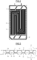
- FIG. 2 shows a front view of the bipolar plate of the fuel cell of FIG. 1 ;
- FIG. 3 shows an enlarged partial cross section of the bipolar plate
- FIG. 4 shows a top view of a straightening machine
- FIG. 5 shows a section of the straightening machine, in a direction of movement.
- a fuel cell 1 in particular comprises a stack 2 of parallelepipedal form, composed of plates overlaid along a stacking axis and attached in an airtight manner, namely a set 3 of unit cells 4 in the form of plates, separated by bipolar plates 5 , thick and rigid end plates 6 and 7 , clamping the assembly 2 , and finally an end block 8 .
- This stack 2 is held by compression means (not shown) such as tie rods.
- Each unit cell 4 comprises three overlaid layers, namely an anode, an electrolyte and a cathode (not shown).
- Each bipolar plate 5 supplies, on one side, fuel, generally hydrogen, to the unit cell adjacent to this side and supplies, on the other side, oxidizer, generally oxygen, to the unit cell adjacent to this other side, so that electrochemical generators are formed.
- each bipolar plate 5 is formed by two overlaid stamped metal sheets 9 and 10 .
- stamped metal sheets 9 and 10 define pluralities of opposite grooves 11 and 12 set back from zones 13 and 14 defining opposite faces 15 and 16 of the polar plate 5 .
- the bottoms 11 a and 12 a of the grooves 11 and 12 are attached and fixed together, for example by welding.
- the grooves 11 and 12 have U-shaped sections with divergent symmetrical legs.
- the faces 15 and 16 are intended to be in contact with the adjacent faces of the adjacent unit cells 4 , so as to define channels 17 and 18 for selectively circulating the fuel and the oxidizer, these channels extending perpendicularly to the axis of the stack according to a desired topography.
- channels 19 which can be used for the circulation of a cooling fluid are defined between the metal sheets 9 and 10 .
- the unit cells 4 in the form of plates and the bipolar plates 5 have pluralities of overlaid axial passages 20 and 21 , defining a plurality of axial ducts 22 into which the channels 17 , 18 and 20 selectively open.
- the end block 8 has a plurality of channels 23 suitable to be connected to outside ducts (which are not shown) and selectively connected to the axial channels 22 through through-passages 24 of the end plate 6 .
- the bipolar plates 5 are manufactured by stamping and welding and have a thickness which is, normally, equal to a desired value. Nevertheless, such manufacturing causes deformations such as curving and warping of the bipolar plates 5 .
- each bipolar plate 5 passes, in a flat manner, each bipolar plate 5 between two rows 25 and 26 of straightening parallel cylindrical rollers 27 and 28 of a straightening machine 29 , which is provided with support means that can be set and with means of rotating these rollers.
- the numbers of the straightening rollers 27 and 28 are such that several of the straightening rollers 27 and 28 can bear on the opposite faces 15 and 16 of the bipolar plate 5 .
- the straightening rollers 27 of the row 25 and the rollers 28 of the rows 26 are offset with respect to one another in the translation direction ( FIG. 5 ), for example by half a pitch.
- the straightening rollers 27 and 28 are rotated by suitable means (not shown), in order to translate the bipolar plate 5 at a suitable translation speed.
- the bipolar plate 5 has a greater number of long grooves 11 and 12 extending in a first direction with respect to that extending in other directions, it is preferable to pass it between the rows 25 and 26 of straightening rollers 27 and 28 so that it moves perpendicularly to this first direction.
- the distance between the rolling opposite planes defined by the straightening rollers 27 and 28 of the rows 25 and 26 is substantially equal to or very close to the desired thickness of the bipolar plate 5 .
- the bipolar plate 5 to be treated undergoes bending deformations, at least at certain points of the movement thereof and in one direction and/or in the other direction, between two straightening successive rollers of one of the rows and the straightening roller of the other row, which roller is located between these two straightening rollers.
- the setting of the distance between the rolling opposite planes of the rows 25 and 26 and the speed of rotation of the rollers 27 and 28 are suitable for producing this effect.
- the bipolar plates 5 that have been corrected and flattened, can be inserted into the assembly 3 , so that the bearing desired pressures between the various plates forming the stack 2 , in order to provide the desired airtightness and optionally the desired electrical contacts, can be obtained with reduced axial forces.
Landscapes
- Engineering & Computer Science (AREA)
- Life Sciences & Earth Sciences (AREA)
- Manufacturing & Machinery (AREA)
- Sustainable Development (AREA)
- Sustainable Energy (AREA)
- Chemical & Material Sciences (AREA)
- Chemical Kinetics & Catalysis (AREA)
- Electrochemistry (AREA)
- General Chemical & Material Sciences (AREA)
- Mechanical Engineering (AREA)
- Fuel Cell (AREA)
Abstract
Description
Claims (9)
Applications Claiming Priority (3)
| Application Number | Priority Date | Filing Date | Title |
|---|---|---|---|
| FR1554610A FR3036539A1 (en) | 2015-05-22 | 2015-05-22 | PROCESS FOR PROCESSING A BIPOLAR PLATE FOR A FUEL CELL |
| FR1554610 | 2015-05-22 | ||
| PCT/EP2016/060967 WO2016188790A1 (en) | 2015-05-22 | 2016-05-17 | Process for treating a bipolar plate for a fuel-cell stack |
Publications (2)
| Publication Number | Publication Date |
|---|---|
| US20180145344A1 US20180145344A1 (en) | 2018-05-24 |
| US10622644B2 true US10622644B2 (en) | 2020-04-14 |
Family
ID=53496867
Family Applications (1)
| Application Number | Title | Priority Date | Filing Date |
|---|---|---|---|
| US15/572,885 Active 2036-12-14 US10622644B2 (en) | 2015-05-22 | 2016-05-17 | Process for treating a bipolar plate for a fuel cell |
Country Status (6)
| Country | Link |
|---|---|
| US (1) | US10622644B2 (en) |
| EP (1) | EP3298645B1 (en) |
| JP (1) | JP6778701B2 (en) |
| CN (1) | CN107864686B (en) |
| FR (1) | FR3036539A1 (en) |
| WO (1) | WO2016188790A1 (en) |
Families Citing this family (6)
| Publication number | Priority date | Publication date | Assignee | Title |
|---|---|---|---|---|
| FR3039931B1 (en) | 2015-08-07 | 2017-08-25 | Michelin & Cie | STACK FOR THE MANUFACTURE OF BIPOLAR PLATES FOR FUEL CELLS |
| FR3060209A1 (en) | 2016-12-12 | 2018-06-15 | Compagnie Generale Des Etablissements Michelin | PROCESS FOR MANUFACTURING MEMBRANE-ELECTRODE ASSEMBLY FOR FUEL CELL |
| FR3060210A1 (en) | 2016-12-12 | 2018-06-15 | Compagnie Generale Des Etablissements Michelin | PROCESS FOR MANUFACTURING MEMBRANE-ELECTRODE ASSEMBLY FOR FUEL CELL |
| CN112234158B (en) * | 2020-10-14 | 2022-04-12 | 湖北亿纬动力有限公司 | A kind of dry powder coating method, pole piece and lithium ion battery prepared by the method |
| CN114171755B (en) * | 2021-10-20 | 2023-08-18 | 海卓动力(上海)能源科技有限公司 | Fuel cell bipolar plate and preparation method thereof |
| WO2026017364A1 (en) * | 2024-07-17 | 2026-01-22 | Robert Bosch Gmbh | Method for processing and leveling bipolar plates |
Citations (5)
| Publication number | Priority date | Publication date | Assignee | Title |
|---|---|---|---|---|
| US20030213276A1 (en) * | 2002-05-14 | 2003-11-20 | Bodnar Ernest R. | Retro-fit roll forming mill with jack screw |
| US7451907B2 (en) | 2004-08-06 | 2008-11-18 | General Motors Corporation | Roll bonding of bipolar plates |
| US20090226785A1 (en) | 2005-06-22 | 2009-09-10 | Nippon Steel Corporation | Stainless Steel, Titanium, or Titanium Alloy Solid Polymer Fuel Cell Separator and Its Method of Produciton and Method of Evaluation of Warp and Twist of Separator |
| US20110281192A1 (en) | 2010-05-13 | 2011-11-17 | Thomas Jones | Method for producing bipolar plates |
| US9853307B2 (en) * | 2007-06-04 | 2017-12-26 | GM Global Technology Operations LLC | Fuel cell stack with improved end cell performance provided by higher modulus of elasticity |
Family Cites Families (3)
| Publication number | Priority date | Publication date | Assignee | Title |
|---|---|---|---|---|
| CN2032515U (en) * | 1988-02-16 | 1989-02-15 | 冶金工业部攀枝花钢铁公司钢铁研究院 | Multi-roll steel straightening machine |
| CN101388465A (en) * | 2007-09-14 | 2009-03-18 | 富准精密工业(深圳)有限公司 | Fuel cell polar plate and fuel cell using the same |
| JP5262150B2 (en) * | 2008-02-05 | 2013-08-14 | 日産自動車株式会社 | Manufacturing method and manufacturing apparatus for metal separator for fuel cell |
-
2015
- 2015-05-22 FR FR1554610A patent/FR3036539A1/en not_active Ceased
-
2016
- 2016-05-17 WO PCT/EP2016/060967 patent/WO2016188790A1/en not_active Ceased
- 2016-05-17 CN CN201680029492.4A patent/CN107864686B/en active Active
- 2016-05-17 US US15/572,885 patent/US10622644B2/en active Active
- 2016-05-17 JP JP2017560771A patent/JP6778701B2/en active Active
- 2016-05-17 EP EP16722899.8A patent/EP3298645B1/en active Active
Patent Citations (5)
| Publication number | Priority date | Publication date | Assignee | Title |
|---|---|---|---|---|
| US20030213276A1 (en) * | 2002-05-14 | 2003-11-20 | Bodnar Ernest R. | Retro-fit roll forming mill with jack screw |
| US7451907B2 (en) | 2004-08-06 | 2008-11-18 | General Motors Corporation | Roll bonding of bipolar plates |
| US20090226785A1 (en) | 2005-06-22 | 2009-09-10 | Nippon Steel Corporation | Stainless Steel, Titanium, or Titanium Alloy Solid Polymer Fuel Cell Separator and Its Method of Produciton and Method of Evaluation of Warp and Twist of Separator |
| US9853307B2 (en) * | 2007-06-04 | 2017-12-26 | GM Global Technology Operations LLC | Fuel cell stack with improved end cell performance provided by higher modulus of elasticity |
| US20110281192A1 (en) | 2010-05-13 | 2011-11-17 | Thomas Jones | Method for producing bipolar plates |
Non-Patent Citations (2)
| Title |
|---|
| International Search Report issued by WIPO dated Jul. 1, 2016, in connection with International Application No. PCT/EP2016/060967 (with English translation attached). |
| Jul. 1, 2016 International Search Report and Written Opinion in International Patent Appln. No. PCT/EP2016/060967. |
Also Published As
| Publication number | Publication date |
|---|---|
| EP3298645A1 (en) | 2018-03-28 |
| JP2018520464A (en) | 2018-07-26 |
| WO2016188790A1 (en) | 2016-12-01 |
| CN107864686B (en) | 2020-10-27 |
| US20180145344A1 (en) | 2018-05-24 |
| EP3298645B1 (en) | 2019-01-23 |
| CN107864686A (en) | 2018-03-30 |
| JP6778701B2 (en) | 2020-11-04 |
| FR3036539A1 (en) | 2016-11-25 |
Similar Documents
| Publication | Publication Date | Title |
|---|---|---|
| US10622644B2 (en) | Process for treating a bipolar plate for a fuel cell | |
| DE102016117232B4 (en) | BIPOLAR PLATE ASSEMBLY AND FUEL CELL STACK | |
| US6818165B2 (en) | Method of fabricating fluid flow field plates | |
| EP2973809B1 (en) | Bipolar plate for a fuel cell, fuel cell and method for producing the bipolar plate | |
| JP2011113806A (en) | Separator for fuel cell and method of manufacturing the same | |
| US20180221934A1 (en) | Die assembly for a stamping press | |
| WO2010054744A1 (en) | Bipolar plate for a fuel cell arrangement, particularly for disposing between two adjacent membrane electrode arrangements in a fuel cell stack | |
| US20170229714A1 (en) | Embossed metal seal design with improved contact pressure uniformity under conditions of misalignment | |
| KR102200739B1 (en) | Manufacturing method of metal separator for fuel cell stack | |
| JP2006228533A (en) | Method of forming separator for fuel cell and separator shape correcting device | |
| DE112007001807T5 (en) | fuel cell | |
| US20180248203A1 (en) | System and method for manufacturing channels in a bipolar plate | |
| DE102007050600B4 (en) | Fuel cell and fuel cell stack with a pressure relief device | |
| JP2018537286A (en) | Channel plate manufacturing apparatus and manufacturing method | |
| DE102016218140B4 (en) | Fuel cell stack with heat pipes | |
| WO2015169543A1 (en) | Bipolar plate, fuel cell and method for producing the bipolar plate | |
| JP5262149B2 (en) | Manufacturing method and manufacturing apparatus for metal separator for fuel cell | |
| DE102009031487A1 (en) | A compliant feed region in an embossed metal flow field of a fuel cell plate for eliminating bias | |
| JP4700393B2 (en) | Multi-stage roll forming equipment | |
| US20150311540A1 (en) | Method for producing fluid flow field plates | |
| JP6500028B2 (en) | Method for manufacturing an electrochemical reactor | |
| WO2012084077A1 (en) | Fuel cell stack | |
| JP2006127948A (en) | Fuel cell stack | |
| JP2004134090A (en) | Method and apparatus for manufacturing stainless steel separator for polymer electrolyte fuel cell | |
| US20070154772A1 (en) | Plate structure for multi-slice fuel cell |
Legal Events
| Date | Code | Title | Description |
|---|---|---|---|
| FEPP | Fee payment procedure |
Free format text: ENTITY STATUS SET TO UNDISCOUNTED (ORIGINAL EVENT CODE: BIG.); ENTITY STATUS OF PATENT OWNER: LARGE ENTITY |
|
| AS | Assignment |
Owner name: COMPAGNIE GENERALE DES ETABLISSEMENTS MICHELIN, FRANCE Free format text: ASSIGNMENT OF ASSIGNORS INTEREST;ASSIGNOR:BLANC, CLAUDE;REEL/FRAME:044315/0727 Effective date: 20171123 Owner name: COMPAGNIE GENERALE DES ETABLISSEMENTS MICHELIN, FR Free format text: ASSIGNMENT OF ASSIGNORS INTEREST;ASSIGNOR:BLANC, CLAUDE;REEL/FRAME:044315/0727 Effective date: 20171123 |
|
| STPP | Information on status: patent application and granting procedure in general |
Free format text: DOCKETED NEW CASE - READY FOR EXAMINATION |
|
| STPP | Information on status: patent application and granting procedure in general |
Free format text: NON FINAL ACTION MAILED |
|
| STPP | Information on status: patent application and granting procedure in general |
Free format text: RESPONSE TO NON-FINAL OFFICE ACTION ENTERED AND FORWARDED TO EXAMINER |
|
| STPP | Information on status: patent application and granting procedure in general |
Free format text: NOTICE OF ALLOWANCE MAILED -- APPLICATION RECEIVED IN OFFICE OF PUBLICATIONS |
|
| STCF | Information on status: patent grant |
Free format text: PATENTED CASE |
|
| MAFP | Maintenance fee payment |
Free format text: PAYMENT OF MAINTENANCE FEE, 4TH YEAR, LARGE ENTITY (ORIGINAL EVENT CODE: M1551); ENTITY STATUS OF PATENT OWNER: LARGE ENTITY Year of fee payment: 4 |