US10622641B2 - Secondary battery anode comprising lithium metal layer having micropattern and protective layer thereof, and method for producing same - Google Patents
Secondary battery anode comprising lithium metal layer having micropattern and protective layer thereof, and method for producing same Download PDFInfo
- Publication number
- US10622641B2 US10622641B2 US16/083,676 US201816083676A US10622641B2 US 10622641 B2 US10622641 B2 US 10622641B2 US 201816083676 A US201816083676 A US 201816083676A US 10622641 B2 US10622641 B2 US 10622641B2
- Authority
- US
- United States
- Prior art keywords
- lithium metal
- negative electrode
- pattern
- lithium
- protective layer
- Prior art date
- Legal status (The legal status is an assumption and is not a legal conclusion. Google has not performed a legal analysis and makes no representation as to the accuracy of the status listed.)
- Active
Links
Images


Classifications
-
- H—ELECTRICITY
- H01—ELECTRIC ELEMENTS
- H01M—PROCESSES OR MEANS, e.g. BATTERIES, FOR THE DIRECT CONVERSION OF CHEMICAL ENERGY INTO ELECTRICAL ENERGY
- H01M4/00—Electrodes
- H01M4/02—Electrodes composed of, or comprising, active material
- H01M4/64—Carriers or collectors
- H01M4/70—Carriers or collectors characterised by shape or form
- H01M4/72—Grids
- H01M4/74—Meshes or woven material; Expanded metal
-
- H—ELECTRICITY
- H01—ELECTRIC ELEMENTS
- H01M—PROCESSES OR MEANS, e.g. BATTERIES, FOR THE DIRECT CONVERSION OF CHEMICAL ENERGY INTO ELECTRICAL ENERGY
- H01M4/00—Electrodes
- H01M4/02—Electrodes composed of, or comprising, active material
- H01M4/13—Electrodes for accumulators with non-aqueous electrolyte, e.g. for lithium-accumulators; Processes of manufacture thereof
- H01M4/134—Electrodes based on metals, Si or alloys
-
- H—ELECTRICITY
- H01—ELECTRIC ELEMENTS
- H01M—PROCESSES OR MEANS, e.g. BATTERIES, FOR THE DIRECT CONVERSION OF CHEMICAL ENERGY INTO ELECTRICAL ENERGY
- H01M10/00—Secondary cells; Manufacture thereof
- H01M10/05—Accumulators with non-aqueous electrolyte
- H01M10/052—Li-accumulators
-
- H—ELECTRICITY
- H01—ELECTRIC ELEMENTS
- H01M—PROCESSES OR MEANS, e.g. BATTERIES, FOR THE DIRECT CONVERSION OF CHEMICAL ENERGY INTO ELECTRICAL ENERGY
- H01M4/00—Electrodes
- H01M4/02—Electrodes composed of, or comprising, active material
-
- H—ELECTRICITY
- H01—ELECTRIC ELEMENTS
- H01M—PROCESSES OR MEANS, e.g. BATTERIES, FOR THE DIRECT CONVERSION OF CHEMICAL ENERGY INTO ELECTRICAL ENERGY
- H01M4/00—Electrodes
- H01M4/02—Electrodes composed of, or comprising, active material
- H01M4/04—Processes of manufacture in general
-
- H—ELECTRICITY
- H01—ELECTRIC ELEMENTS
- H01M—PROCESSES OR MEANS, e.g. BATTERIES, FOR THE DIRECT CONVERSION OF CHEMICAL ENERGY INTO ELECTRICAL ENERGY
- H01M4/00—Electrodes
- H01M4/02—Electrodes composed of, or comprising, active material
- H01M4/04—Processes of manufacture in general
- H01M4/0402—Methods of deposition of the material
- H01M4/0404—Methods of deposition of the material by coating on electrode collectors
-
- H—ELECTRICITY
- H01—ELECTRIC ELEMENTS
- H01M—PROCESSES OR MEANS, e.g. BATTERIES, FOR THE DIRECT CONVERSION OF CHEMICAL ENERGY INTO ELECTRICAL ENERGY
- H01M4/00—Electrodes
- H01M4/02—Electrodes composed of, or comprising, active material
- H01M4/04—Processes of manufacture in general
- H01M4/0402—Methods of deposition of the material
- H01M4/0421—Methods of deposition of the material involving vapour deposition
- H01M4/0423—Physical vapour deposition
-
- H—ELECTRICITY
- H01—ELECTRIC ELEMENTS
- H01M—PROCESSES OR MEANS, e.g. BATTERIES, FOR THE DIRECT CONVERSION OF CHEMICAL ENERGY INTO ELECTRICAL ENERGY
- H01M4/00—Electrodes
- H01M4/02—Electrodes composed of, or comprising, active material
- H01M4/04—Processes of manufacture in general
- H01M4/043—Processes of manufacture in general involving compressing or compaction
-
- H—ELECTRICITY
- H01—ELECTRIC ELEMENTS
- H01M—PROCESSES OR MEANS, e.g. BATTERIES, FOR THE DIRECT CONVERSION OF CHEMICAL ENERGY INTO ELECTRICAL ENERGY
- H01M4/00—Electrodes
- H01M4/02—Electrodes composed of, or comprising, active material
- H01M4/13—Electrodes for accumulators with non-aqueous electrolyte, e.g. for lithium-accumulators; Processes of manufacture thereof
- H01M4/139—Processes of manufacture
- H01M4/1393—Processes of manufacture of electrodes based on carbonaceous material, e.g. graphite-intercalation compounds or CFx
-
- H—ELECTRICITY
- H01—ELECTRIC ELEMENTS
- H01M—PROCESSES OR MEANS, e.g. BATTERIES, FOR THE DIRECT CONVERSION OF CHEMICAL ENERGY INTO ELECTRICAL ENERGY
- H01M4/00—Electrodes
- H01M4/02—Electrodes composed of, or comprising, active material
- H01M4/13—Electrodes for accumulators with non-aqueous electrolyte, e.g. for lithium-accumulators; Processes of manufacture thereof
- H01M4/139—Processes of manufacture
- H01M4/1395—Processes of manufacture of electrodes based on metals, Si or alloys
-
- H—ELECTRICITY
- H01—ELECTRIC ELEMENTS
- H01M—PROCESSES OR MEANS, e.g. BATTERIES, FOR THE DIRECT CONVERSION OF CHEMICAL ENERGY INTO ELECTRICAL ENERGY
- H01M4/00—Electrodes
- H01M4/02—Electrodes composed of, or comprising, active material
- H01M4/36—Selection of substances as active materials, active masses, active liquids
- H01M4/362—Composites
- H01M4/366—Composites as layered products
-
- H—ELECTRICITY
- H01—ELECTRIC ELEMENTS
- H01M—PROCESSES OR MEANS, e.g. BATTERIES, FOR THE DIRECT CONVERSION OF CHEMICAL ENERGY INTO ELECTRICAL ENERGY
- H01M4/00—Electrodes
- H01M4/02—Electrodes composed of, or comprising, active material
- H01M4/36—Selection of substances as active materials, active masses, active liquids
- H01M4/38—Selection of substances as active materials, active masses, active liquids of elements or alloys
- H01M4/381—Alkaline or alkaline earth metals elements
- H01M4/382—Lithium
-
- H—ELECTRICITY
- H01—ELECTRIC ELEMENTS
- H01M—PROCESSES OR MEANS, e.g. BATTERIES, FOR THE DIRECT CONVERSION OF CHEMICAL ENERGY INTO ELECTRICAL ENERGY
- H01M4/00—Electrodes
- H01M4/02—Electrodes composed of, or comprising, active material
- H01M4/62—Selection of inactive substances as ingredients for active masses, e.g. binders, fillers
-
- H—ELECTRICITY
- H01—ELECTRIC ELEMENTS
- H01M—PROCESSES OR MEANS, e.g. BATTERIES, FOR THE DIRECT CONVERSION OF CHEMICAL ENERGY INTO ELECTRICAL ENERGY
- H01M4/00—Electrodes
- H01M4/02—Electrodes composed of, or comprising, active material
- H01M4/64—Carriers or collectors
- H01M4/66—Selection of materials
- H01M4/663—Selection of materials containing carbon or carbonaceous materials as conductive part, e.g. graphite, carbon fibres
-
- H—ELECTRICITY
- H01—ELECTRIC ELEMENTS
- H01M—PROCESSES OR MEANS, e.g. BATTERIES, FOR THE DIRECT CONVERSION OF CHEMICAL ENERGY INTO ELECTRICAL ENERGY
- H01M4/00—Electrodes
- H01M4/02—Electrodes composed of, or comprising, active material
- H01M4/64—Carriers or collectors
- H01M4/70—Carriers or collectors characterised by shape or form
- H01M4/75—Wires, rods or strips
-
- H—ELECTRICITY
- H01—ELECTRIC ELEMENTS
- H01M—PROCESSES OR MEANS, e.g. BATTERIES, FOR THE DIRECT CONVERSION OF CHEMICAL ENERGY INTO ELECTRICAL ENERGY
- H01M4/00—Electrodes
- H01M4/02—Electrodes composed of, or comprising, active material
- H01M2004/026—Electrodes composed of, or comprising, active material characterised by the polarity
- H01M2004/027—Negative electrodes
-
- Y—GENERAL TAGGING OF NEW TECHNOLOGICAL DEVELOPMENTS; GENERAL TAGGING OF CROSS-SECTIONAL TECHNOLOGIES SPANNING OVER SEVERAL SECTIONS OF THE IPC; TECHNICAL SUBJECTS COVERED BY FORMER USPC CROSS-REFERENCE ART COLLECTIONS [XRACs] AND DIGESTS
- Y02—TECHNOLOGIES OR APPLICATIONS FOR MITIGATION OR ADAPTATION AGAINST CLIMATE CHANGE
- Y02E—REDUCTION OF GREENHOUSE GAS [GHG] EMISSIONS, RELATED TO ENERGY GENERATION, TRANSMISSION OR DISTRIBUTION
- Y02E60/00—Enabling technologies; Technologies with a potential or indirect contribution to GHG emissions mitigation
- Y02E60/10—Energy storage using batteries
Definitions
- the present disclosure relates to a negative electrode for a secondary battery and a method of manufacturing the same, and more particularly to a negative electrode including a lithium metal having a fine pattern shape and a protective layer thereof and a method of manufacturing the same, and a secondary battery including the same.
- the electrochemical devices are the most remarkable field in such an aspect, and among them, development of secondary batteries capable of charging and discharging has been the focus of attention.
- research and development to design new electrodes and batteries capable of improving capacity density and specific energy have been progressed in developing such a secondary battery.
- lithium secondary batteries developed in the early 1990s have been in the spotlight due to advantages such as higher operating voltage and much greater energy density than conventional batteries such as Ni-MH batteries, Ni—Cd batteries, sulfuric acid-lead batteries, or the like using an aqueous electrolyte.
- a general method of manufacturing a lithium secondary battery includes applying a slurry including a positive electrode active material and a negative electrode active material to each current collector and then winding or laminating together with a separator as an insulator to manufacture and prepare an electrode assembly, inserting the electrode assembly into a battery case, injecting an electrolyte into the battery case and sealing the battery case, and degassing to remove gas generated during the initial formation.
- a lithium metal negative electrode has been examined as a negative electrode capable of achieving energy density 10 times higher than that of a conventional graphite negative electrode (theoretical capacity: 372 mAh/g) with a low standard hydrogen potential ( ⁇ 3.04 V vs. SHE) and a high theoretical capacity (3,860 mAh/g)
- a lithium metal as a negative electrode of a lithium ion secondary battery
- problems such as a poor electrode life cycle and safety of the lithium metal, which is related to strong reactivity of the lithium metal.
- Li 2 CO 3 , Li 2 O, LiOH, etc. are formed on a surface of the lithium metal according to the type of gas present in the atmosphere.
- a type of passivation film is formed on the surface of the lithium metal by reaction with a solute or solvent of the electrolyte, and such a film is referred to as a solid electrolyte interface (SEI) layer,
- SEI solid electrolyte interface
- the native film or the passivation film makes current density nonuniform on a surface of the lithium metal and reduces a surface area required for dissolution and deposition of lithium.
- the form of deposited lithium is related to the charge and discharge current density, the type of an electrolyte, and the growth of lithium in the form of dendrites, moss, and sphere. A part of the lithium that grows in the form of dendrite is broken during discharge to form dead lithium. Although it is impossible to electrochemically charge and discharge the dead lithium, it has chemically strong reactivity.
- the present disclosure is provided to solve the above-described problems of the related art and technical problems which are identified in the past. Specifically, the present disclosure is directed to maximize capacity of a battery by preventing lithium consumption in a battery, which is caused by formation of a native film or a passivation film of lithium metal.
- a negative electrode for a secondary battery which is a negative electrode having a negative electrode current collector and a lithium metal, the negative electrode including: a negative electrode current collector; a lithium metal layer having a fine pattern formed on the negative electrode current collector; and a protective layer formed along a surface of the lithium metal layer having the fine pattern.
- a shape of the pattern may have any one of a mesh shape, a lamellar shape, an embo shape, a linear shape, a circular shape, an elliptical shape, a polygonal shape, and a waveform shape.
- the protective layer may be formed by depositing carbon or lithium fluoride (LiF) on a surface of the lithium metal.
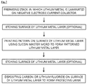
- a method for preparing a negative electrode for a secondary battery which has a lithium metal having a pattern and a protective layer, the method including: disposing a pattern mask on a negative electrode current collector; forming a lithium metal layer having the pattern by depositing the lithium metal on the negative electrode current collector on which the pattern mask is disposed; and depositing carbon or lithium fluoride (LiF) on a surface of the lithium metal layer having the fine pattern to form the protective layer.
- a process of etching the surface of the lithium metal may be further included after forming the lithium metal layer having the pattern.
- the lithium metal may be deposited on the negative electrode current collector using any one method of thermal vapor deposition (TVD), physical vapor deposition (PVD), sputtering deposition, and spin coating deposition.
- TVD thermal vapor deposition
- PVD physical vapor deposition
- sputtering deposition spin coating deposition
- a method for preparing a negative electrode for a secondary battery which has a lithium metal having a pattern and a protective layer, the method including: laminating the lithium metal on a negative electrode current collector to manufacture a stack; forming a lithium metal layer having a pattern by printing the pattern on the lithium metal using a silicon master mold; and depositing carbon or lithium fluoride (LiF) on a surface of the lithium metal layer having the fine pattern to form the protective layer.
- LiF lithium fluoride
- a process of etching the surface of the lithium metal may be further included at any stage before or after the process of forming the lithium metal layer having the pattern.
- a method of forming the protective layer along the surface of the lithium metal having the fine pattern may use any one method of thermal vapor deposition (TVD), physical vapor deposition (PVD), or sputtering deposition.
- TVD thermal vapor deposition
- PVD physical vapor deposition
- sputtering deposition any one method of vapor deposition
- a method of etching the surface of the lithium metal may be either inert gas plasma sputtering or plasma etching.
- a lithium secondary battery including a positive electrode, a negative electrode, a separator interposed between the positive electrode and the negative electrode, and an electrolyte in which a lithium salt is dissolved, and the negative electrode is the negative electrode of claim 1 .
- effective current density can be reduced and battery capacity can be maximized by forming a fine pattern on a surface of a lithium metal included in a negative electrode to increase an electrode specific surface area.
- an increase in battery resistance can be prevented and charge and discharge cycle efficiency can be improved by forming pattern on a surface of a lithium metal to improve an interfacial adhesion between the lithium metal and a protective layer thereof.
- FIG. 1 is a SEM image of a lithium metal surface on which a fine pattern is formed in a negative electrode for a secondary battery according to the present disclosure.
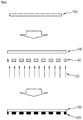
- FIG. 2 is a schematic view showing a series of manufacturing processes of forming a lithium metal layer having a fine pattern using a pattern mask and a protective layer thereof.
- FIG. 3 is a view showing a process of disposing a pattern mask on a negative electrode current collector and then depositing lithium on the negative electrode current collector by the TVD method to form a lithium metal layer having a fine pattern.
- FIG. 4 is a view showing an exemplary embodiment of forming a protective layer on the surface of a lithium metal layer having fine pattern.
- FIG. 5 is a view showing a principle of a thermal vapor deposition among the methods of depositing lithium in FIG. 3 .
- FIG. 6 is a view showing an exemplary embodiment of a sputtering method, which is one of the methods of forming a protective layer on the surface of a lithium metal layer having a fine pattern in FIG. 4 and FIG. 8 .
- FIG. 7 is a schematic view showing a series of manufacturing processes of forming a lithium metal layer and a protective layer thereof by a method of forming a fine pattern by a printing technique using a silicon master mold.
- FIG. 8 is a view showing a series of manufacturing processes of forming a lithium metal layer and a protective layer thereof by a method of forming a fine pattern by a printing technique using a silicon master mold.
- the present disclosure relates to a negative electrode including a negative electrode current collector and a lithium metal, the negative electrode including: a negative electrode current collector; a lithium metal layer having a fine pattern formed on the negative electrode current collector; and a protective layer formed along the surface of the lithium metal layer having a fine pattern.
- effective current density may be reduced and battery capacity may be maximized by forming a fine pattern on a surface of a lithium metal included in a negative electrode to increase an electrode specific surface area, and an increase in battery resistance may be prevented and charge and discharge cycle efficiency may be improved by forming a pattern on a surface of a lithium metal to improve an interfacial adhesion between a lithium metal and a protective layer thereof.
- Li 2 CO 3 , Li 2 O, LiOH, or the like are formed on a surface of the lithium metal according to the type of gas, referred to as a native film, present in the air atmosphere.
- the native film or a passivation film makes a current density non-uniform at a surface of the lithium metal and reduces a surface area required for dissolution and adsorption of lithium. Accordingly, in order to suppress the formation of such a native film, a protective layer is deposited on a surface of a lithium metal so that permeation of an electrolyte and moisture may be blocked.
- an interfacial adhesion between a lithium metal layer and a protective layer may be improved by forming a pattern on a surface of lithium metal in a process prior to depositing the protective layer on the surface of the lithium metal, and finally, an electrode specific surface area may be increased so that an effective current density may be decreased and a capacity of a battery may be maximized.
- a shape of the pattern is not particularly limited, but preferably has any one of a mesh shape, a lamellar shape, an embo shape, a linear shape, a circular shape, an elliptical shape, a polygonal shape, and a waveform shape.
- the lithium metal may be in a form of a foil or sheet.
- a method of connecting the lithium metal to a negative electrode is not particularly limited, but specifically, one entire surface of the lithium metal may be connected to the negative electrode by depositing or placing the lithium metal on a negative electrode current collector to make planar contact.
- the negative electrode current collector may be made of platinum (Pt), gold (Au), palladium (Pd), iridium (Ir), silver (Ag), ruthenium (Ru), nickel (Ni), stainless steel (STS), copper (Cu), molybdenum (Mo), chromium (Cr), carbon (C), titanium (Ti), tungsten (W), In doped SnO2 (ITO), F doped SnO2 (FTO), and an alloy thereof, and a material obtained by surface-treating carbon (C), nickel (Ni), titanium (Ti) or silver (Ag) on a surface of copper (Cu) or stainless steel, but is not necessarily limited thereto.
- a shape of the negative electrode current collector is not particularly limited, and may be in a form of, for example, a foil, a film, a sheet, a punched material, a porous body, a foam, or the like.
- a copper material, and more specifically, a perforated copper foil is used as the negative electrode current collector.
- the protective layer formed on the surface of the lithium metal includes an inorganic compound or an organic compound having ion conductivity, and carbon or lithium fluoride (LiF) is used in the present disclosure.
- a method of forming the protective layer on the lithium metal it is preferable to deposit carbon or lithium fluoride (LiF) on the lithium metal using any one method of thermal vapor deposition (TVD), physical vapor deposition (PVD), or sputtering deposition.
- the protective layer formed using such a method has lithium ion conductivity and allows lithium ions to pass between the negative electrode and an electrolyte.
- the protective layer suppresses a reaction between the electrolyte and the negative electrode, suppresses an increase of an internal resistance of the battery, and improves reversibility of a deposition and dissolution reaction of lithium.
- a short circuit phenomenon due to formation of dendrites from the negative electrode may be prevented, and a lifespan of a charging and discharging cycle may be increased.
- a lithium secondary battery of the present disclosure including the negative electrode manufactured as described above is advantageous in that the effective current density is decreased to maximize the capacity of the battery, the resistance of the battery is prevented from being increased, and charging and discharging cycle efficiency is excellent.
- FIG. 2 shows a series of preparing processes for forming a lithium metal layer having a fine pattern and a protective layer thereof using a pattern mask.
- an exemplary example for preparing a negative electrode according to the present disclosure includes: disposing a pattern mask 40 on a negative electrode current collector 100 having a thickness of 5 to 20 ⁇ m; forming a lithium metal layer 200 having a fine pattern by depositing a lithium metal 20 on the negative electrode current collector 100 on which the pattern mask 40 is disposed; and depositing carbon or lithium fluoride (LiF) on a surface of the lithium metal layer 200 having the fine pattern to form a protective layer 300 .
- LiF lithium fluoride
- the negative electrode current collector is not particularly limited as long as it has conductivity without causing adverse chemical changes to the battery. Although a thickness of the negative electrode current collector is generally 3 to 500 ⁇ m, the negative electrode current collector having a thickness of 5 to 20 ⁇ m is used in the present disclosure. When the thickness of the negative electrode current collector is less than 5 ⁇ m, production efficiency is not great, and when the thickness exceeds 20 ⁇ m, a capacity per volume of a lithium battery decreases.
- a method of depositing lithium metal on the negative electrode current collector is not particularly limited, but it is preferable to use any one method of thermal vapor deposition (TVD), physical vapor deposition (PVD), sputtering deposition, and spin coating deposition.
- FIG. 5 is a view showing a principle of a TVD method among the methods of depositing lithium metal.
- the lithium metal in order to form a lithium metal layer having a fine pattern, is deposited by the above described deposition methods after a pattern mask 40 is disposed on a negative electrode current collector 100 .
- the lithium metal as a deposition material may be deposited only on a portion of the negative electrode current collector 100 corresponding to voids of the pattern mask 40 so that the lithium metal layer 200 having the fine pattern is formed.
- a process of etching the surface of the lithium metal may be further included after forming the lithium metal layer having the pattern using the above described methods.
- the etching process on the surface of lithium metal is performed to remove impurities or a native film of the lithium metal.
- an increase in an internal resistance is suppressed in comparison to a case in which the etching process is not performed, thereby achieving an increased lifespan of a charging and discharging cycle.
- the lithium metal layer having the fine pattern may be formed by using a silicon master mold in addition to the method of using the above described pattern mask.
- FIGS. 7 and 8 show a series of preparing processes for forming a lithium metal layer having a fine pattern and a protective layer thereof by a printing technique using a silicon master mold. Referring to FIGS.
- a method for preparing a negative electrode for a secondary battery includes laminating a lithium metal 10 on a negative electrode current collector 100 to manufacture a stack having a thickness of 10 to 300 ⁇ m, printing a pattern using a silicon master mold 50 on the lithium metal 10 to form a lithium metal layer 200 having a fine pattern; and depositing carbon or lithium fluoride (LiF) on a surface of the lithium metal layer 200 having the fine pattern to form a protective layer 300 .
- LiF lithium fluoride
- a thickness of the negative electrode current collector 100 and the lithium metal stack may be 10 to 300 ⁇ m. When the thickness is less than 10 ⁇ m, productivity is degraded, and when the thickness exceeds 300 ⁇ m, a capacity per volume of a lithium battery is decreased.
- lithium metal is a relatively flexible metal
- the silicon master mold 50 which is harder than the lithium metal, is disposed on the lithium metal 10 and pressure is applied to the silicon master mold 50 by a press 60 , an etching form of the silicon master mold 50 is directly transferred onto the surface of the lithium metal 10 .
- the fine pattern may be formed on the lithium metal 10 using such a transcription technique.
- any silicon master mold manufactured according to any known technique may be used to form a pattern on the lithium metal.
- a desired shape may be transferred onto a photoresist by disposing a photomask of the desired shape on a silicon wafer coated with the photoresist and being exposed to ultraviolet rays. Then, silicon is etched according to the desired shape to manufacture the silicon master mold.
- a process of etching the surface of the lithium metal may be further included at any stage before or after a process of forming the lithium metal layer having the pattern.
- the etching is performed on the surface of lithium metal to remove impurities or a native film of the lithium metal.
- the native film is removed prior to depositing the protective layer, an increase in an internal resistance is suppressed in comparison to a case in which the etching process is not performed, thereby maximizing the capacity of the secondary battery.
- the protective layer is formed along the patterned surface of the lithium metal after the lithium metal layer having a fine pattern as described above is manufactured.
- the protective layer is not limited as long as it has a material capable of blocking permeation of an electrolyte and moisture, but carbon or lithium fluoride may be used.
- a method of forming the protective layer is not particularly limited, but it is preferable to form the protective layer by thermal vapor deposition (TVD), physical vapor deposition (PVD), or sputtering deposition.
- FIG. 6 shows an example of forming the protective layer by depositing carbon on the surface of the lithium metal by argon sputtering. Meanwhile, when depositing a material having a low melting point like lithium fluoride, it may be advantageous to use a thermal vapor deposition (TVD) method.
- TVD thermal vapor deposition
- the protective layer formed using such a method has lithium ion conductivity and allows lithium ions to pass between a negative electrode and an electrolyte.
- the protective layer suppresses a reaction between the electrolyte and the negative electrode, suppresses an increase of an internal resistance of the battery, and improves reversibility of a deposition and dissolution reaction of lithium.
- a short circuit phenomenon due to formation of dendrites from the negative electrode may be prevented, and the capacity of the lithium secondary battery may be maximized.
- the etching process is performed on the surface of the lithium metal to remove impurities or a native film of the lithium metal.
- an etching treatment method is not particularly limited, but it is preferable to use either an inert gas plasma sputtering method or a plasma etching method.
- a pattern mask having a mesh-shaped pattern was disposed on a copper foil in a vacuum chamber and lithium metal was deposited by a thermal vapor deposition (TVD) method (target:Li) at a temperature of 300° C. for 60 minutes under an argon gas atmosphere to form a lithium metal layer having a fine mesh-shaped pattern. Thereafter, the pattern mask was removed, and carbon was deposited on a surface of the lithium metal by a plasma sputtering method under vacuum for 60 minutes.
- TVD thermal vapor deposition
- a positive electrode mixture slurry was manufactured by adding 96 wt % of LiCoO2 as a positive electrode active material, 2 wt % of Denka black as a conductive material, and 2 wt % of polyvinylidene fluoride (PVDF) as a binder to N-Methyl-2-Pyrrolidone (NMP).
- PVDF polyvinylidene fluoride
- NMP N-Methyl-2-Pyrrolidone
- the lithium metal manufactured by the above described method was used as a negative electrode, a polyolefin separator was interposed between the positive electrode and the negative electrode, and an electrolyte in which 1M lithium hexafluorophosphate (LiPF 6 ) was dissolved was injected into a solvent in which ethylene carbonate (EC) and ethyl methyl carbonate (DEC) were mixed at a volume ratio of 50:50 to manufacture a coin type half-cell.
- EC ethylene carbonate
- DEC ethyl methyl carbonate
- a coin type half-cell was manufactured in the same manner as in Example 1, except that lithium fluoride, instead of carbon, was deposited on the surface of the lithium metal of Example 1 on which the pattern was formed by using a thermal vapor deposition (TVD) method (target:LiF).
- TVD thermal vapor deposition
- a coin type half-cell was manufactured in the same manner as in Example 1, except that the pattern had a waveform shape.
- a coin type half-cell was manufactured in the same manner as in Example 1, except that the pattern had a circular shape.
- a coin type half-cell was manufactured in the same manner as in Example 2, except that the pattern formed on the surface of the lithium metal had a waveform shape.
- a coin type half-cell was manufactured in the same manner as in Example 2, except that the pattern formed on the surface of the lithium metal had a circular shape.
- a pattern mask having a mesh-shaped pattern was disposed on a copper foil in a vacuum chamber and lithium metal was deposited by a thermal vapor deposition (TVD) method at a temperature of 300° C. for 60 minutes under an argon gas atmosphere to form a lithium metal layer having a fine mesh-shaped pattern. Thereafter, the pattern mask was removed and a native film was etched by an argon plasma sputtering method for 30 minutes. Carbon was deposited on the surface of the lithium metal from which the native film had been removed under vacuum for 60 minutes by a plasma sputtering method.
- TVD thermal vapor deposition
- a coin type half-cell was manufactured in the same manner as in Example 1, except that the lithium metal obtained by the above described method was used as a negative electrode.
- a coin type half-cell was manufactured in the same manner as in Example 7, except that lithium fluoride instead of carbon was deposited on the surface of the lithium metal of Example 7 on which the pattern was formed by using a thermal vapor deposition (TVD) method (target:LiF).
- TVD thermal vapor deposition
- a coin type half-cell was manufactured in the same manner as in Example 7, except that the pattern formed on the surface of the lithium metal had a waveform shape.
- a coin type half-cell was manufactured in the same manner as in Example 7, except that the pattern formed on the surface of the lithium metal had a circular shape.
- a coin type half-cell was manufactured in the same manner as in Example 8, except that the pattern formed on the surface of the lithium metal had a waveform shape.
- a coin type half-cell was manufactured in the same manner as in Example 8, except that the pattern formed on the surface of the lithium metal had a circular shape.
- a silicon master mold having a mesh-shaped pattern was disposed on an upper portion of the lithium metal. Thereafter, a force was applied to the silicon master mold to transfer the pattern of the silicon master mold onto the surface of the lithium metal, thereby preparing a lithium metal having a fine pattern.
- the obtained lithium metal and copper foil stack were placed in a vacuum chamber and a native film was removed by an argon plasma sputtering method under vacuum for 30 minutes. The surface of the lithium metal from which the native film had been removed was subjected to a plasma sputtering method under vacuum for 60 minutes to manufacture a carbon-deposited lithium metal.
- a coin type half-cell was manufactured in the same manner as in Example 1, except that the lithium metal manufactured as described above was used as a negative electrode.
- a coin type half-cell was manufactured in the same manner as in Example 13, except that lithium fluoride, instead of carbon, was deposited on the surface of the lithium metal of Example 13 on which the pattern was formed by using a thermal vapor deposition (TVD) method (target:LiF).
- TVD thermal vapor deposition
- a coin type half-cell was manufactured in the same manner as in Example 13, except that the pattern formed on the surface of the lithium metal had a waveform shape.
- a coin type half-cell was manufactured in the same manner as in Example 13, except that the pattern formed on the surface of the lithium metal had a circular shape.
- a coin type half-cell was manufactured in the same manner as in Example 14, except that the shape of the pattern formed on the surface of the lithium metal had a waveform shape.
- a coin type half-cell was manufactured in the same manner as in Example 14, except that the pattern formed on the surface of the lithium metal had a circular shape.
- the copper foil and the lithium metal were placed in a vacuum chamber and a native film was removed by an argon plasma sputtering method under vacuum for 30 minutes.
- a silicon master mold having a mesh-shaped pattern was disposed on an upper portion of the lithium metal from which the native film has been removed. Thereafter, a force was applied to the silicon master mold to transfer the pattern of the silicon master mold onto the surface of the lithium metal.
- the lithium metal and copper foil stack having a fine pattern were subjected to a plasma sputtering method under vacuum for 60 minutes to manufacture a carbon-deposited lithium metal.
- a coin type half-cell was manufactured in the same manner as in Example 1, except that the lithium metal manufactured as described above was used as a negative electrode.
- a coin type half-cell was manufactured in the same manner as in Example 19, except that lithium fluoride, instead of carbon, was deposited on the surface of the lithium metal of Example 19 on which the pattern was formed by using a thermal vapor deposition (TVD) method (target:LiF).
- TVD thermal vapor deposition
- a coin type half-cell was manufactured in the same manner as in Example 19, except that the pattern formed on the surface of the lithium metal had a waveform shape.
- a coin type half-cell was manufactured in the same manner as in Example 19, except that the pattern formed on the surface of the lithium metal had a circular shape.
- a coin type half-cell was manufactured in the same manner as in Example 20, except that the pattern formed on the surface of the lithium metal had a waveform shape.
- a coin type half-cell was manufactured in the same manner as in Example 20, except that the pattern formed on the surface of the lithium metal had a circular shape.
- a positive electrode mixture slurry was manufactured by adding 96 wt % of LiCoO2 as a positive electrode active material, 2 wt % of Denka black as a conductive material, and 2 wt % of polyvinylidene fluoride (PVDF) as a binder to N-Methyl-2-Pyrrolidone (NMP).
- PVDF polyvinylidene fluoride
- NMP N-Methyl-2-Pyrrolidone
- the lithium metal (150 ⁇ m, extruded lithium) foil in the state as received was used as a negative electrode, a polyolefin separator was interposed between the positive electrode and the negative electrode, and an electrolyte in which 1M lithium hexafluorophosphate (LiPF 6 ) was dissolved was injected into a solvent in which ethylene carbonate (EC) and ethyl methyl carbonate (DEC) were mixed at a volume ratio of 50:50 to manufacture a coin type half-cell.
- EC ethylene carbonate
- DEC ethyl methyl carbonate
- a coin type half-cell was manufactured in the same manner as in Comparative Example 1, except that a lithium metal manufactured by placing the lithium metal (150 ⁇ m, extruded lithium) in the state as received in a vacuum chamber and etching a native film by an argon plasma sputtering method under vacuum for 30 minutes was used as a negative electrode.
- a coin type half-cell was manufactured in the same manner as in Comparative Example 1, except that a lithium metal manufactured by depositing carbon on the surface of the lithium metal (150 ⁇ m, extruded lithium) in the state as received by a plasma sputtering method under vacuum for 60 minutes was used as a negative electrode.
- a coin type half-cell was manufactured in the same manner as in Comparative Example 1, except that a lithium metal manufactured by depositing lithium fluoride on the surface of the lithium metal (150 ⁇ m, extruded lithium) in the state as received by a thermal vapor deposition (TVD) method under vacuum was used as a negative electrode.
- a lithium metal manufactured by depositing lithium fluoride on the surface of the lithium metal (150 ⁇ m, extruded lithium) in the state as received by a thermal vapor deposition (TVD) method under vacuum was used as a negative electrode.
- a coin type half-cell was manufactured in the same manner as in Comparative Example 1, except that a lithium metal manufactured by depositing carbon on the surface of the lithium metal from which a native film was removed, instead of being coated with lithium metal foil of Comparative Example 1 by a plasma sputtering method (target:graphite) under vacuum for 60 minutes was used as a negative electrode.
- a lithium metal manufactured by depositing carbon on the surface of the lithium metal from which a native film was removed instead of being coated with lithium metal foil of Comparative Example 1 by a plasma sputtering method (target:graphite) under vacuum for 60 minutes was used as a negative electrode.
- a coin type half-cell was manufactured in the same manner as in Comparative Example 1, except that a lithium metal manufactured by depositing lithium fluoride on the surface of the lithium metal from which a native film was removed, instead of being coated with lithium metal foil of Comparative Example 1 by a thermal vapor deposition (TVD) method (target:LiF) under vacuum for 60 minutes was used as a negative electrode.
- a lithium metal manufactured by depositing lithium fluoride on the surface of the lithium metal from which a native film was removed instead of being coated with lithium metal foil of Comparative Example 1 by a thermal vapor deposition (TVD) method (target:LiF) under vacuum for 60 minutes was used as a negative electrode.
- TVD thermal vapor deposition
- the coin type half-cells manufactured by the methods of Examples 1 to 24 and Comparative Examples 1 to 6 were charged and discharged by using an electrochemical charging and discharging device.
- the charging was performed until the voltage reached 4.4 V vs. Li/Li +
- the discharging was performed until the voltage reached 3.0 V vs. Li/LI +
- current density was applied at 0.5 C-rate.
- Capacity Retention Rate (%) (100th Discharge Capacity/First Discharge Capacity) ⁇ 100
- a negative electrode for a secondary battery which is composed of a lithium metal layer having a fine pattern of the present disclosure and a protective layer formed along a surface of the lithium metal layer having the fine pattern, has an effect of maximizing a capacity of a battery.
Abstract
Description
Capacity Retention Rate (%)=(100th Discharge Capacity/First Discharge Capacity)×100
| TABLE 1 | |||||||
| Etching | |||||||
| Pattern | Process | First | 100th | ||||
| Shape Of | Performed | Discharging | Discharging | Capacity | |||
| Lithium | Patterning | Or Not | Protective | Capacity | Capacity | Retention | |
| Type | Metal | method | And When | Layer | (mAh/g) | (mAh/g) | Rate (%) |
| Example 1 | Mesh | Pattern | X | Carbon | 169.3 | 60.3 | 35.6 |
| Mask | |||||||
| Example 2 | Mesh | X | Lithium | 168.4 | 52.6 | 31.2 | |
| Fluoride | |||||||
| Example 3 | Waveform | X | Carbon | 168.5 | 59.7 | 35.4 | |
| Example 4 | Circle | X | Carbon | 169.1 | 60.4 | 35.7 | |
| Example 5 | Waveform | X | Lithium | 168.5 | 51.9 | 30.8 | |
| Fluoride | |||||||
| Example 6 | Circle | X | Lithium | 170.0 | 52.0 | 30.5 | |
| Fluoride | |||||||
| Example 7 | Mesh | ◯ | Carbon | 170.0 | 75.0 | 44.1 | |
| Example 8 | Mesh | ◯ | Lithium | 169.5 | 68.9 | 40.6 | |
| Fluoride | |||||||
| Example 9 | Waveform | ◯ | Carbon | 170.1 | 75.2 | 44.2 | |
| Example 10 | Circle | ◯ | Carbon | 169.8 | 75.3 | 44.3 | |
| Example 11 | Waveform | ◯ | Lithium | 170.1 | 69.0 | 40.5 | |
| Fluoride | |||||||
| Example 12 | Circle | ◯ | Lithium | 170.1 | 68.9 | 40.5 | |
| Fluoride | |||||||
| Example 13 | Mesh | Silicone | ◯ (After | Carbon | 170.3 | 76.1 | 44.6 |
| Master | Pattern Was | ||||||
| Mold | Formed) | ||||||
| Example 14 | Mesh | ◯ (After | Lithium | 169.5 | 66.1 | 38.9 | |
| Pattern Was | Fluoride | ||||||
| Formed) | |||||||
| Example 15 | Waveform | ◯ (After | Carbon | 170.2 | 75.9 | 44.5 | |
| Pattern Was | |||||||
| Formed) | |||||||
| Example 16 | Circle | ◯ (After | Carbon | 170.5 | 76.5 | 44.8 | |
| Pattern Was | |||||||
| Formed) | |||||||
| Example 17 | Waveform | ◯ (After | Lithium | 169.8 | 64.5 | 37.9 | |
| Pattern Was | Fluoride | ||||||
| Formed) | |||||||
| Example 18 | Circle | ◯ (After | Lithium | 169.9 | 65.2 | 38.3 | |
| Pattern Was | Fluoride | ||||||
| Formed) | |||||||
| Example 19 | Mesh | ◯ (Before | Carbon | 170.1 | 75.9 | 44.6 | |
| Pattern Was | |||||||
| Formed) | |||||||
| Example 20 | Mesh | ◯ (Before | Lithium | 169.9 | 65.5 | 38.5 | |
| Pattern Was | Fluoride | ||||||
| Formed) | |||||||
| Example 21 | Waveform | ◯ (Before | Carbon | 170.2 | 76.9 | 45.1 | |
| Pattern Was | |||||||
| Formed) | |||||||
| Example 22 | Circle | ◯ (Before | Carbon | 170.3 | 77.2 | 45.3 | |
| Pattern Was | |||||||
| Formed) | |||||||
| Example 23 | Waveform | ◯ (Before | Lithium | 170.1 | 68.1 | 40.0 | |
| Pattern Was | Fluoride | ||||||
| Formed) | |||||||
| Example 24 | Circle | ∘ (Before | Lithium | 170.2 | 67.8 | 39.8 | |
| Pattern Was | Fluoride | ||||||
| Formed) | |||||||
| Comparative | X | — | X | X | 169.5 | 32.6 | 19.3 |
| Example 1 | |||||||
| Comparative | X | — | ∘ | X | 170.3 | 39.6 | 23.2 |
| Example 2 | |||||||
| Comparative | X | — | X | Carbon | 169.3 | 55.3 | 32.7 |
| Example 3 | |||||||
| Comparative | X | — | X | Lithium | 168.2 | 49.8 | 29.6 |
| Example 4 | Fluoride | ||||||
| Comparative | X | — | ∘ | Carbon | 170.4 | 72.2 | 42.4 |
| Example 5 | |||||||
| Comparative | X | — | ∘ | Lithium | 169.8 | 62.3 | 36.7 |
| Example 6 | Fluoride | ||||||
- 10: Lithium Metal
- 20: Lithium Vapor
- 30: Carbon Plasma
- 40: Pattern Mask
- 50: Silicone Master Mold
- 60: Press
- 100: Negative Electrode Current Collector
- 200: Lithium Metal layer having Fine Pattern
- 300: Lithium Metal Layer coated with Protective Layer
Claims (10)
Applications Claiming Priority (3)
| Application Number | Priority Date | Filing Date | Title |
|---|---|---|---|
| KR10-2017-0006944 | 2017-01-16 | ||
| KR1020170006944A KR102168331B1 (en) | 2017-01-16 | 2017-01-16 | An anode for lithium secondary battery with lithium metal layer having fine patterns and protective layer |
| PCT/KR2018/000504 WO2018131899A1 (en) | 2017-01-16 | 2018-01-11 | Secondary battery anode comprising lithium metal layer having micropattern and protective layer thereof, and method for producing same |
Publications (2)
| Publication Number | Publication Date |
|---|---|
| US20190074520A1 US20190074520A1 (en) | 2019-03-07 |
| US10622641B2 true US10622641B2 (en) | 2020-04-14 |
Family
ID=62840607
Family Applications (1)
| Application Number | Title | Priority Date | Filing Date |
|---|---|---|---|
| US16/083,676 Active US10622641B2 (en) | 2017-01-16 | 2018-01-11 | Secondary battery anode comprising lithium metal layer having micropattern and protective layer thereof, and method for producing same |
Country Status (8)
| Country | Link |
|---|---|
| US (1) | US10622641B2 (en) |
| EP (1) | EP3416220B1 (en) |
| KR (1) | KR102168331B1 (en) |
| CN (1) | CN108886150B (en) |
| ES (1) | ES2926161T3 (en) |
| HU (1) | HUE059666T2 (en) |
| PL (1) | PL3416220T3 (en) |
| WO (1) | WO2018131899A1 (en) |
Families Citing this family (6)
| Publication number | Priority date | Publication date | Assignee | Title |
|---|---|---|---|---|
| CN110112417B (en) * | 2019-04-25 | 2022-07-05 | 浙江锋锂新能源科技有限公司 | Elastic lithium metal negative electrode surface modification layer, preparation method thereof and lithium metal negative electrode |
| KR102397170B1 (en) | 2020-07-09 | 2022-05-12 | 한국기계연구원 | Fine pattern fabricating system and method for fabricating fine pattern using the same |
| CN112103553A (en) * | 2020-10-21 | 2020-12-18 | 上海交通大学烟台信息技术研究院 | Novel lithium ion battery or lithium battery and preparation method thereof |
| CN112366287B (en) * | 2020-10-30 | 2022-04-19 | 蜂巢能源科技(无锡)有限公司 | Lithium metal cathode with three-dimensional structure, and preparation method and application thereof |
| CN114788046A (en) * | 2020-11-02 | 2022-07-22 | 株式会社Lg新能源 | Negative electrode for lithium metal battery, method for manufacturing same, and lithium metal battery comprising same |
| CN113036070A (en) * | 2021-03-03 | 2021-06-25 | 昆山宝创新能源科技有限公司 | Negative active film layer and preparation method thereof, pre-lithiation method, negative pole piece and lithium battery |
Citations (10)
| Publication number | Priority date | Publication date | Assignee | Title |
|---|---|---|---|---|
| JPH06223820A (en) | 1993-01-21 | 1994-08-12 | Mitsubishi Cable Ind Ltd | Negative electrode for lithium secondary battery |
| JPH07201357A (en) | 1994-01-06 | 1995-08-04 | Asahi Chem Ind Co Ltd | Lighium battery |
| US6063142A (en) | 1994-12-01 | 2000-05-16 | Canon Kabushiki Kaisha | Process for producing a rechargeable lithium battery having an improved anode coated by a film containing a specific metal oxide material |
| JP3570128B2 (en) | 1996-12-05 | 2004-09-29 | ソニー株式会社 | Manufacturing method of non-aqueous electrolyte secondary battery |
| JP2009266464A (en) | 2008-04-23 | 2009-11-12 | Panasonic Corp | Manufacturing method of lithium battery |
| KR20130067920A (en) | 2011-12-14 | 2013-06-25 | 한국전자통신연구원 | Carbon powder coated li anode for lithium rechargeable batteries |
| KR20130122578A (en) | 2012-04-30 | 2013-11-07 | 주식회사 엘지화학 | Secondary battery comprising solid electrolyte battery having a lithium ion-path, method for producing the same |
| KR20140142576A (en) | 2013-06-04 | 2014-12-12 | 주식회사 엘지화학 | Manufacturing method of electrode for secondary battery and secondary battery comprising electrode manufactured by the method |
| JP2016154112A (en) | 2015-02-20 | 2016-08-25 | エレクセル株式会社 | Lithium ion secondary battery |
| EP3486976A1 (en) | 2017-01-09 | 2019-05-22 | LG Chem, Ltd. | Patterning for lithium metal and electrochemical device using same |
Family Cites Families (11)
| Publication number | Priority date | Publication date | Assignee | Title |
|---|---|---|---|---|
| JPS57128B2 (en) | 1972-05-31 | 1982-01-05 | ||
| JP3812324B2 (en) * | 2000-11-06 | 2006-08-23 | 日本電気株式会社 | Lithium secondary battery and manufacturing method thereof |
| KR100413796B1 (en) * | 2001-05-31 | 2004-01-03 | 삼성에스디아이 주식회사 | Method of manufacturing lithium metal anode protective layer for lithium battery |
| CN1179432C (en) * | 2001-05-31 | 2004-12-08 | 三星Sdi株式会社 | Method for forming lithium metal positive-pole protective layer of lithium cell |
| JP2003045415A (en) * | 2001-07-31 | 2003-02-14 | Nec Corp | Negative electrode for secondary battery |
| KR100485091B1 (en) * | 2002-10-25 | 2005-04-22 | 삼성에스디아이 주식회사 | Negative electrode for lithium secondary battery and lithium secondary battery comprising same |
| CN101290987A (en) * | 2008-06-05 | 2008-10-22 | 天津中能锂业有限公司 | Minus pole of coin type lithium battery, preparing method thereof and coin type lithium battery comprising the minus pole |
| US9017865B2 (en) * | 2010-09-29 | 2015-04-28 | Panasonic Intellectual Property Management Co., Ltd. | Lithium primary battery and method of producing same |
| KR101156225B1 (en) * | 2010-11-17 | 2012-06-18 | 고려대학교 산학협력단 | Lithium deposited anode for Lithium Second Battery and Method for Preparation thereof |
| US10256448B2 (en) * | 2014-07-10 | 2019-04-09 | The Board Of Trustees Of The Leland Stanford Junior University | Interfacial engineering for stable lithium metal anodes |
| CN105633338B (en) * | 2016-03-25 | 2017-12-15 | 张五星 | A kind of preparation method of secondary cell composite metal negative pole and products thereof |
-
2017
- 2017-01-16 KR KR1020170006944A patent/KR102168331B1/en active IP Right Grant
-
2018
- 2018-01-11 WO PCT/KR2018/000504 patent/WO2018131899A1/en active Application Filing
- 2018-01-11 US US16/083,676 patent/US10622641B2/en active Active
- 2018-01-11 PL PL18739084.4T patent/PL3416220T3/en unknown
- 2018-01-11 CN CN201880001406.8A patent/CN108886150B/en active Active
- 2018-01-11 ES ES18739084T patent/ES2926161T3/en active Active
- 2018-01-11 EP EP18739084.4A patent/EP3416220B1/en active Active
- 2018-01-11 HU HUE18739084A patent/HUE059666T2/en unknown
Patent Citations (12)
| Publication number | Priority date | Publication date | Assignee | Title |
|---|---|---|---|---|
| JPH06223820A (en) | 1993-01-21 | 1994-08-12 | Mitsubishi Cable Ind Ltd | Negative electrode for lithium secondary battery |
| JPH07201357A (en) | 1994-01-06 | 1995-08-04 | Asahi Chem Ind Co Ltd | Lighium battery |
| US6063142A (en) | 1994-12-01 | 2000-05-16 | Canon Kabushiki Kaisha | Process for producing a rechargeable lithium battery having an improved anode coated by a film containing a specific metal oxide material |
| JP3347555B2 (en) | 1994-12-01 | 2002-11-20 | キヤノン株式会社 | Method for manufacturing negative electrode of lithium secondary battery |
| JP3570128B2 (en) | 1996-12-05 | 2004-09-29 | ソニー株式会社 | Manufacturing method of non-aqueous electrolyte secondary battery |
| JP2009266464A (en) | 2008-04-23 | 2009-11-12 | Panasonic Corp | Manufacturing method of lithium battery |
| KR20130067920A (en) | 2011-12-14 | 2013-06-25 | 한국전자통신연구원 | Carbon powder coated li anode for lithium rechargeable batteries |
| KR20130122578A (en) | 2012-04-30 | 2013-11-07 | 주식회사 엘지화학 | Secondary battery comprising solid electrolyte battery having a lithium ion-path, method for producing the same |
| KR20140142576A (en) | 2013-06-04 | 2014-12-12 | 주식회사 엘지화학 | Manufacturing method of electrode for secondary battery and secondary battery comprising electrode manufactured by the method |
| JP2016154112A (en) | 2015-02-20 | 2016-08-25 | エレクセル株式会社 | Lithium ion secondary battery |
| EP3255708A1 (en) | 2015-02-20 | 2017-12-13 | Elexcel Corporation Ltd. | Lithium-ion secondary battery |
| EP3486976A1 (en) | 2017-01-09 | 2019-05-22 | LG Chem, Ltd. | Patterning for lithium metal and electrochemical device using same |
Non-Patent Citations (5)
| Title |
|---|
| International Search Report for PCT/KR2018/00504 dated May 8, 2018. |
| JOONAM PARK, JISEON JEONG, YUNJU LEE, MIN OH, MYUNG-HYUN RYOU, YONG MIN LEE: "Micro-Patterned Lithium Metal Anodes with Suppressed Dendrite Formation for Post Lithium-Ion Batteries", ADVANCED MATERIALS INTERFACES, WILEY - V C H VERLAG GMBH & CO. KGAA, DE, vol. 3, no. 11, 1 June 2016 (2016-06-01), DE, pages 1600140, XP055580573, ISSN: 2196-7350, DOI: 10.1002/admi.201600140 |
| MYUNG-HYUN RYOU, YONG MIN LEE, YUNJU LEE, MARTIN WINTER AND PETER BIEKER: "Mechanical Surface Modification of Lithium Metal: Towards Improved Li Metal Anode Performance by Directed Li Plating", ADVANCED FUNCTIONAL MATERIALS, WILEY-VCH, WEINHEIM, vol. 25, no. 6, 11 February 2015 (2015-02-11), weinheim, pages 834 - 841, XP001595266, DOI: 10.1002/adfm.201402953 |
| Park et al., "Micro-patterned lithium metal anodes with suppressed dendrite formation for post lithium-ion batteries," Advanced Materials Interfaces, vol. 3, No. 11, 2016, 9 pages, XP055580573. |
| Ryou et al., "Mechanical surface modification of lithium metal: towards improved Li metal anode performance by directed Li plating," Advanced Functional Materials, vol. 25, No. 6, 2015, pp. 834-841, XP001595266. |
Also Published As
| Publication number | Publication date |
|---|---|
| EP3416220B1 (en) | 2022-07-13 |
| HUE059666T2 (en) | 2022-12-28 |
| CN108886150A (en) | 2018-11-23 |
| US20190074520A1 (en) | 2019-03-07 |
| CN108886150B (en) | 2022-02-01 |
| ES2926161T3 (en) | 2022-10-24 |
| EP3416220A4 (en) | 2019-07-10 |
| PL3416220T3 (en) | 2022-09-19 |
| WO2018131899A1 (en) | 2018-07-19 |
| KR20180084204A (en) | 2018-07-25 |
| EP3416220A1 (en) | 2018-12-19 |
| KR102168331B1 (en) | 2020-10-22 |
Similar Documents
| Publication | Publication Date | Title |
|---|---|---|
| US10622641B2 (en) | Secondary battery anode comprising lithium metal layer having micropattern and protective layer thereof, and method for producing same | |
| US7427455B2 (en) | Anode for lithium metal polymer secondary battery comprising surface patterned anodic current collector and method of preparing the same | |
| KR101156225B1 (en) | Lithium deposited anode for Lithium Second Battery and Method for Preparation thereof | |
| JP4642835B2 (en) | Current collector for electrode | |
| JP3896025B2 (en) | Secondary battery electrode | |
| KR20180041086A (en) | An anode for an lithium ion secondary battery and a method for manufacturing the same | |
| JP5334156B2 (en) | Method for producing non-aqueous electrolyte secondary battery | |
| JPH08167429A (en) | Rechargeable electrochemical cell and its manufacture | |
| WO2018024203A1 (en) | Pole piece and electrochemical cell | |
| US9196897B2 (en) | Secondary battery porous electrode | |
| CN112072076B (en) | Modification method for surface of negative electrode of lithium metal battery | |
| CN114678514B (en) | Patterned lithium metal, electrode for secondary battery comprising same, and secondary battery | |
| KR20020051829A (en) | Nonaqueous electrolyte secondary battery | |
| JP4138326B2 (en) | Method for producing non-aqueous electrolyte secondary battery | |
| JP3795614B2 (en) | Non-aqueous electrolyte secondary battery charge / discharge method | |
| KR20150133376A (en) | Electrode for a lithium secondary battery, method of forming the same and lithium secondary battery | |
| KR102557568B1 (en) | Anode-free all solid state battery comprising solid electrolyte having high ion conductivity and surface-roughened anode current collector | |
| KR102312027B1 (en) | Method for manufacturing pattern current collector for seawater battery and the pattern current collector for seawater battery manufactured using the same | |
| KR100566592B1 (en) | Anode foil for lithium ion polymer battery and method thereof | |
| JP4145061B2 (en) | Method for producing electrode for lithium secondary battery | |
| JPH0729596A (en) | Lithium secondary battery | |
| CN117894995A (en) | Composite current collector and electrochemical device comprising same | |
| CN115676888A (en) | Modified lithium tantalate modified graphene nano material and preparation method and application thereof | |
| JP2011082008A (en) | Electrode for electrochemical element, method of manufacturing the same, and lithium ion battery | |
| JPH0729597A (en) | Lithium secondary battery |
Legal Events
| Date | Code | Title | Description |
|---|---|---|---|
| FEPP | Fee payment procedure |
Free format text: ENTITY STATUS SET TO UNDISCOUNTED (ORIGINAL EVENT CODE: BIG.); ENTITY STATUS OF PATENT OWNER: LARGE ENTITY |
|
| AS | Assignment |
Owner name: LG CHEM, LTD., KOREA, REPUBLIC OF Free format text: ASSIGNMENT OF ASSIGNORS INTEREST;ASSIGNORS:WOO, SANG WOOK;SHON, JEONG WOO;CHAE, OH BYONG;AND OTHERS;SIGNING DATES FROM 20180826 TO 20180827;REEL/FRAME:047480/0007 |
|
| STPP | Information on status: patent application and granting procedure in general |
Free format text: DOCKETED NEW CASE - READY FOR EXAMINATION |
|
| STPP | Information on status: patent application and granting procedure in general |
Free format text: NON FINAL ACTION MAILED |
|
| STPP | Information on status: patent application and granting procedure in general |
Free format text: RESPONSE TO NON-FINAL OFFICE ACTION ENTERED AND FORWARDED TO EXAMINER |
|
| STPP | Information on status: patent application and granting procedure in general |
Free format text: NOTICE OF ALLOWANCE MAILED -- APPLICATION RECEIVED IN OFFICE OF PUBLICATIONS |
|
| STCF | Information on status: patent grant |
Free format text: PATENTED CASE |
|
| AS | Assignment |
Owner name: LG ENERGY SOLUTION, LTD., KOREA, REPUBLIC OF Free format text: ASSIGNMENT OF ASSIGNORS INTEREST;ASSIGNOR:LG CHEM, LTD.;REEL/FRAME:058295/0068 Effective date: 20211027 |
|
| MAFP | Maintenance fee payment |
Free format text: PAYMENT OF MAINTENANCE FEE, 4TH YEAR, LARGE ENTITY (ORIGINAL EVENT CODE: M1551); ENTITY STATUS OF PATENT OWNER: LARGE ENTITY Year of fee payment: 4 |