US10619974B2 - Thumb-actuated locking holster - Google Patents
Thumb-actuated locking holster Download PDFInfo
- Publication number
- US10619974B2 US10619974B2 US16/364,141 US201916364141A US10619974B2 US 10619974 B2 US10619974 B2 US 10619974B2 US 201916364141 A US201916364141 A US 201916364141A US 10619974 B2 US10619974 B2 US 10619974B2
- Authority
- US
- United States
- Prior art keywords
- holster
- lever
- handgun
- thumb
- receiving
- Prior art date
- Legal status (The legal status is an assumption and is not a legal conclusion. Google has not performed a legal analysis and makes no representation as to the accuracy of the status listed.)
- Active
Links
- 210000003813 thumb Anatomy 0.000 claims abstract description 213
- 230000007246 mechanism Effects 0.000 claims abstract description 132
- 230000014759 maintenance of location Effects 0.000 claims abstract description 115
- 230000000903 blocking effect Effects 0.000 claims description 34
- 230000000994 depressogenic effect Effects 0.000 claims description 5
- 230000000694 effects Effects 0.000 claims description 3
- 239000002184 metal Substances 0.000 claims 2
- 229920000642 polymer Polymers 0.000 abstract description 16
- 230000007704 transition Effects 0.000 abstract description 5
- 230000000881 depressing effect Effects 0.000 abstract description 3
- 239000010410 layer Substances 0.000 description 36
- 230000008901 benefit Effects 0.000 description 29
- 210000003811 finger Anatomy 0.000 description 19
- 210000000245 forearm Anatomy 0.000 description 14
- 238000003780 insertion Methods 0.000 description 11
- 230000037431 insertion Effects 0.000 description 11
- 238000000034 method Methods 0.000 description 8
- 210000003205 muscle Anatomy 0.000 description 7
- 210000002435 tendon Anatomy 0.000 description 7
- 230000008569 process Effects 0.000 description 6
- 229920002725 thermoplastic elastomer Polymers 0.000 description 5
- 239000004677 Nylon Substances 0.000 description 4
- 230000007423 decrease Effects 0.000 description 4
- 229910003460 diamond Inorganic materials 0.000 description 4
- 239000010432 diamond Substances 0.000 description 4
- 238000004519 manufacturing process Methods 0.000 description 4
- 238000012986 modification Methods 0.000 description 4
- 230000004048 modification Effects 0.000 description 4
- 229920001778 nylon Polymers 0.000 description 4
- 210000005224 forefinger Anatomy 0.000 description 3
- 230000006872 improvement Effects 0.000 description 3
- 239000000463 material Substances 0.000 description 3
- 241001125879 Gobio Species 0.000 description 2
- 230000009471 action Effects 0.000 description 2
- 230000009977 dual effect Effects 0.000 description 2
- 238000002347 injection Methods 0.000 description 2
- 239000007924 injection Substances 0.000 description 2
- 238000001746 injection moulding Methods 0.000 description 2
- 230000013011 mating Effects 0.000 description 2
- 239000012815 thermoplastic material Substances 0.000 description 2
- NEWKHUASLBMWRE-UHFFFAOYSA-N 2-methyl-6-(phenylethynyl)pyridine Chemical compound CC1=CC=CC(C#CC=2C=CC=CC=2)=N1 NEWKHUASLBMWRE-UHFFFAOYSA-N 0.000 description 1
- 239000004952 Polyamide Substances 0.000 description 1
- 230000006978 adaptation Effects 0.000 description 1
- 230000008859 change Effects 0.000 description 1
- 238000004140 cleaning Methods 0.000 description 1
- 230000009194 climbing Effects 0.000 description 1
- 230000002153 concerted effect Effects 0.000 description 1
- 230000008602 contraction Effects 0.000 description 1
- 238000013461 design Methods 0.000 description 1
- 239000002355 dual-layer Substances 0.000 description 1
- 238000010304 firing Methods 0.000 description 1
- 238000010348 incorporation Methods 0.000 description 1
- 230000002401 inhibitory effect Effects 0.000 description 1
- 238000012423 maintenance Methods 0.000 description 1
- 238000000465 moulding Methods 0.000 description 1
- 239000004033 plastic Substances 0.000 description 1
- 229920002647 polyamide Polymers 0.000 description 1
- 230000009467 reduction Effects 0.000 description 1
- 230000008439 repair process Effects 0.000 description 1
- 230000000717 retained effect Effects 0.000 description 1
- 238000006748 scratching Methods 0.000 description 1
- 230000002393 scratching effect Effects 0.000 description 1
- 238000000926 separation method Methods 0.000 description 1
- 238000005728 strengthening Methods 0.000 description 1
- 229920001169 thermoplastic Polymers 0.000 description 1
Images


Classifications
-
- F—MECHANICAL ENGINEERING; LIGHTING; HEATING; WEAPONS; BLASTING
- F41—WEAPONS
- F41C—SMALLARMS, e.g. PISTOLS, RIFLES; ACCESSORIES THEREFOR
- F41C33/00—Means for wearing or carrying smallarms
- F41C33/02—Holsters, i.e. cases for pistols having means for being carried or worn, e.g. at the belt or under the arm
- F41C33/0236—Half-holsters covering by encircling only a part of the small arm, e.g. ghost-holsters
-
- A—HUMAN NECESSITIES
- A45—HAND OR TRAVELLING ARTICLES
- A45F—TRAVELLING OR CAMP EQUIPMENT: SACKS OR PACKS CARRIED ON THE BODY
- A45F5/00—Holders or carriers for hand articles; Holders or carriers for use while travelling or camping
- A45F5/02—Fastening articles to the garment
- A45F5/021—Fastening articles to the garment to the belt
-
- F—MECHANICAL ENGINEERING; LIGHTING; HEATING; WEAPONS; BLASTING
- F41—WEAPONS
- F41C—SMALLARMS, e.g. PISTOLS, RIFLES; ACCESSORIES THEREFOR
- F41C33/00—Means for wearing or carrying smallarms
- F41C33/02—Holsters, i.e. cases for pistols having means for being carried or worn, e.g. at the belt or under the arm
- F41C33/0263—Holsters, i.e. cases for pistols having means for being carried or worn, e.g. at the belt or under the arm having a locking system for preventing unauthorized or accidental removal of the small arm from the holster
-
- F—MECHANICAL ENGINEERING; LIGHTING; HEATING; WEAPONS; BLASTING
- F41—WEAPONS
- F41C—SMALLARMS, e.g. PISTOLS, RIFLES; ACCESSORIES THEREFOR
- F41C33/00—Means for wearing or carrying smallarms
- F41C33/02—Holsters, i.e. cases for pistols having means for being carried or worn, e.g. at the belt or under the arm
- F41C33/0272—Holsters, i.e. cases for pistols having means for being carried or worn, e.g. at the belt or under the arm having means for facilitating or accelerating the drawing of the small arm from the holster
-
- F—MECHANICAL ENGINEERING; LIGHTING; HEATING; WEAPONS; BLASTING
- F41—WEAPONS
- F41C—SMALLARMS, e.g. PISTOLS, RIFLES; ACCESSORIES THEREFOR
- F41C33/00—Means for wearing or carrying smallarms
- F41C33/02—Holsters, i.e. cases for pistols having means for being carried or worn, e.g. at the belt or under the arm
- F41C33/04—Special attachments therefor
- F41C33/041—Special attachments therefor for connecting a holster to a belt, webbing or other object
- F41C33/043—Special attachments therefor for connecting a holster to a belt, webbing or other object for connection in more than one transversal position
-
- F—MECHANICAL ENGINEERING; LIGHTING; HEATING; WEAPONS; BLASTING
- F41—WEAPONS
- F41C—SMALLARMS, e.g. PISTOLS, RIFLES; ACCESSORIES THEREFOR
- F41C33/00—Means for wearing or carrying smallarms
- F41C33/02—Holsters, i.e. cases for pistols having means for being carried or worn, e.g. at the belt or under the arm
- F41C33/04—Special attachments therefor
- F41C33/041—Special attachments therefor for connecting a holster to a belt, webbing or other object
- F41C33/045—Special attachments therefor for connecting a holster to a belt, webbing or other object for connection in more than one rotational position around an axle, e.g. by using a rotatable connection
-
- A—HUMAN NECESSITIES
- A45—HAND OR TRAVELLING ARTICLES
- A45F—TRAVELLING OR CAMP EQUIPMENT: SACKS OR PACKS CARRIED ON THE BODY
- A45F2200/00—Details not otherwise provided for in A45F
- A45F2200/05—Holder or carrier for specific articles
- A45F2200/0591—Defense articles, e.g. small arms, handguns, pistols, or the like
Definitions
- the handgun In many countries (e.g., Germany, Tru and the United States) law enforcement officers often carry a handgun in an openly visible manner while on duty.
- the handgun is typically carried in a holster designed to protect the handgun and hold it securely.
- the holster may include a belt loop that allows it to be hung from a wide belt, for example, a police officer's service belt.
- the holster may also include a locking mechanism to prevent an assailant from drawing the holster user's weapon and prevent the handgun from inadvertently falling out of the holster, for example, when the holster user is running, climbing over a fence, etc. It is important that the retention mechanisms are secure in such challenging situation.
- a holster that securely retains a handgun and that provides improvement in ease of use when the handgun is urgently needed would be welcomed by the industry.
- a holster for receiving and holding a handgun having a trigger guard comprises a polymer holster body and an elongate polymer pivoting lever that together define a handgun retention mechanism that is thumb actuated and moves a trigger guard block portion of the lever between retention and release positions.
- a thumb button depressible toward the handgun is optimally positioned on the user side of the holster, is framed by the holster body and is shielded by thumb guides which may be projecting portions of the body or by components both above and below (with respect to the handgun orientation) the thumb button. In the same motion of grasping the handgun the thumb button is depressed releasing the handgun.
- a feature and advantage of this arrangement is that unintended access to the handgun release, specifically the thumb button, particularly by others, is limited, while allowing intuitive and easy user access to the thumb button by user's thumb when grasping the handgun.
- buttons that release trigger guard block portions are known, such buttons are not well protected from inadvertent actuation, or actuation by others and could use improvement in intuitively accessing such buttons by the user.
- the holster may be a level- 2 configuration, with one active restraint, for example the trigger guard, or a level- 3 configuration, with two active restraints. Both the level 2 configuration and the level 3 configuration utilize the optimally positioned thumb button and may include the elongate polymer pivoting lever that selectively engages the trigger guard of the handgun.
- the level- 3 holster configuration also includes a hood or shroud, such as a U-shaped shroud, that is pivotally supported by the holster body so that the U-shaped shroud selectively pivots between a handgun retaining position in which the U-shaped shroud extends across a rearward opening of the cavity and a release position in which the U-shaped shroud is displaced from the rearward opening so that a withdrawal path of the handgun is unobstructed.
- a hood or shroud such as a U-shaped shroud
- a thumb button of the retaining mechanism is positioned to allow for an intuitive and ergonomic release of the handgun from the holster by positioning the thumb button on the user's side of the holster exactly forward (with respect to the handgun) of the upper handgrip or backstrap recess; the handgrip or backstrap recess is located below the handgun slide of holstered handgun.
- the thumb button is sized and positioned to receive the inside surface of the thumb at the distal knuckle. The thumb button is actuated by depressing it toward the handgun and is spaced about one half inch or less from the handgun body.
- This arrangement advantageously allows the user to actuate the thumb button and release the handgun with much less or no concerted effort of depressing a release button. While the forearm is extending in a downward direction, grasping of the holstered handgun is with less tension in the muscles and tendons of the thumb and forearm.
- the thumb button position as described provides for natural and comfortable movement of the thumb, the same movement as grasping the handgun. It is noted that the mechanics of the muscles and tendons of the thumb and forearm when downward readily accomplish this grip and handgun release, the mechanics change when the forearm is extending in a horizontal direction away from the torso of the handgun user.
- the master grip is facilitated in embodiments, both level two and level three, where the thumb button has no holster body portions or other holster components directly rearward of the rearward margin of the thumb button, and no holster body portions below the thumb button.
- the thumb button has no holster body portions or other holster components directly rearward of the rearward margin of the thumb button, and no holster body portions below the thumb button.
- Such embodiments provide the feature and advantage that as the handgun is withdrawn, the user's thumb slides off of the thumb button into immediate contact with the handgun. That is, there is no engagement with the exterior surface of the holster body by the user's thumb either during actuation of the release of the retention mechanism or as the handgun is withdrawn.
- the thumb button is positioned in close proximity to the surface of the handgun, the thumb movement inward as the thumb transitions from engagement with the button to engagement with the body of the handgun is minimal.
- a holster for receiving a handgun having a trigger guard comprises a holster body having a plurality of holster wall portions defining a rearward opening cavity with a handgun receiving and withdrawal axis.
- the holster has a first handgun retention mechanism, a second handgun retention mechanism, and a thumb receiving tab that actuates both the first handgun retention mechanism and the second handgun retention mechanism.
- each handgun retention mechanism selectively prevents the handgun from being withdrawn from the cavity defined by the wall portions of the holster body.
- the first handgun retention mechanism may comprise a lever pivotally supported by the holster body.
- the lever has an elongate central portion, a depressible portion, and a blocking portion.
- the depressible portion of the lever comprises a first arm extending away from the elongate central portion in a first direction so that the elongate central portion and the first arm cooperate to form a first L-shape.
- the blocking portion of the lever comprises a second arm extending away from the elongate central portion in a second direction opposite the first direction so that the elongate central portion and the second arm cooperate to form a second L-shape.
- the entire lever having a stretched Z shape.
- the lever is pivotally supported by the holster body so that the lever pivots about a lever axis that extends in upward and downward directions with respect to the worn holster, and forward and rearward with the handgun orientation.
- the lever pivots between a handgun trigger guard capture position and a handgun trigger guard release position. The blocking portion of the lever extends into a trigger guard portion of the holster body while the lever is disposed in the handgun trigger guard capture position.
- the second handgun retention mechanism may comprise a hood or shroud, for example a U-shaped hood or shroud that is pivotally supported by the holster body so that the U-shaped shroud selectively pivots between a handgun retaining position in which the U-shaped shroud extends across a rearward opening of the cavity and a release position in which the U-shaped shroud extends forward of the rearward opening so that a withdrawal path of the handgun is unobstructed.
- a hood or shroud for example a U-shaped hood or shroud that is pivotally supported by the holster body so that the U-shaped shroud selectively pivots between a handgun retaining position in which the U-shaped shroud extends across a rearward opening of the cavity and a release position in which the U-shaped shroud extends forward of the rearward opening so that a withdrawal path of the handgun is unobstructed.
- the holster includes a U-shaped shroud that is part of a hood assembly including a bracket that captures the U-shaped shroud and defines a slot.
- the holster includes a leaf spring that is received in the bracket slot when the U-shaped shroud is in the handgun retaining position. A spring biases the U-shaped shroud to pivot toward a handgun withdrawal position.
- depression of the thumb button causes the lever to rotate through a first range of rotary motion and causes deflection of the leaf spring so that a distal portion of the leaf spring is outside of the slot.
- further depression of the thumb button causing rotation of the lever through a second range of rotary motion causes the thumb button to engage the depressible portion of the lever causing at least part of the blocking portion of the lever to be withdrawn from the trigger guard receiving portion of the holster body releasing the trigger guard and allowing removal of the handgun.
- two handgun retention mechanisms utilize pivoting components rather than sliding components, this is believed to generally reduce the size, complexity, and reliability of the mechanisms and components. Additionally the two actuatable handgun retention mechanisms, and particularly the pivoting components, are mounted on the exterior of the holster body, thereby simplifying assembly, operation, maintenance, and cleaning, if needed.
- the holster body is formed from two polymers, one overmolded onto the other, providing an interior layer and an exterior layer.
- the interior layer being softer than the exterior layer minimizing any wear, damage or markings on the exterior surface of the handgun.
- the interior layer and the exterior layer are combined using an injection molding “overmolding” process where one layer in injection molded onto the previously molded layer.
- the interior layer comprises a thermoplastic elastomer (TPE) and the exterior layer a thermoplastic material.
- the interior layer comprises a polymer such as Hytrel and the exterior layer comprises a polyamide material (e.g., nylon).
- the holster body is formed to provide a handgun fitting function that can be adjusted by rotating a tensioning screw.
- the shape of the forward portion of the handgun can be conceptualized as a rectangle and the shape of the cavity defined by the holster body can be configured to make point contact with the four corners of the rectangular handgun portion.
- the shape of the cavity defined by the holster body can be conceptualized as two opposing V-shapes, and upper V-shape and a lower V-shape. The two legs of the upper V-shape and the two legs of the lower V-shape may each contact one corner of the rectangle.
- the lower V-shape defines a split near the lower end of the V-shape.
- a tensioning screw is positioned to selectively decrease the angle between the two legs of the lower V-shape. As the angle between the two legs of the lower V-shape decreases, the two legs of the lower V-shape apply upwardly directed component forces to the corresponding corners of the rectangular handgun portion. The forces applied to the lower corners of the rectangular handgun portion urge the upper corners of the rectangle against the two legs of the upper V-shape.
- the softer inner layer provides a higher level of friction to the insertion and withdrawal of the handgun and thus the adjustment of the tensioning screw is more sensitive and effective in controlling the friction associated with a handgun withdrawal compared to the same configuration with a harder plastic interior surface.
- a feature and advantage of embodiments is a retention mechanism has two distinct separated pivoting connections forming a hinge portion of the handgun retention mechanism.
- the hinge portion of the retention mechanism has a hinge length extending between the outer end portions of the two pivot portions.
- a ratio of the hinge length to the overall length of the elongate lever is greater than 0.8. This arrangement provides stability of attachment, robustness and ease of assembly. This arrangement also places less stress on the holster body.
- the pivot portions of the lever and pivot of the body are coupled using a simple assembly process with no separate hinge pin.
- a rearward pivoting connection and a forward pivoting connection of the retention mechanism may each be formed from a pair of cooperating connector pivot portions.
- a forward pivot portion is a pin portion and the other forward pivot portion is a C-shaped pin receiving portion.
- One of the rearward pivot portions may be a pin portion and the other of the rearward pivot portions may be a C-shaped pin receiving portion.
- One of the rearward pivot portions may be integrally formed with the holster body and the other of the rearward pivot portions may be integrally formed with the lever.
- One of the forward pivot portions may be integrally formed with the holster body and the other of the forward pivot portions may be integrally formed with the lever.
- a feature and advantage of embodiments is a pivoting arrangement having a pin portion that snaps into a corresponding C-shaped portion. This arrangement provides manufacturing advantages including fewer parts, easier assembly, the possibility of performing a repair by replacing the lever, and the possibility of replacing the lever with one or more levers having alternate configurations to suit the preferences of different users.
- a feature and advantage of embodiments is a pivoting handgun release arrangement in a holster made almost entirely of polymeric material, except for springs and fasteners. This arrangement provides ease of assembly and cost efficiencies by minimizing the number of parts and minimizing the number of assembly steps.
- the pivoting arrangement includes a polymer pin portion that is received in a corresponding C-shaped portion.
- a feature and advantage of embodiments is a retention mechanism in a holster that is thumb actuated to selectively release the handgun when the user wishes to draw his or her weapon.
- the release actuation mechanism includes a pivoting lever. The blocking portion of the lever pivots from the blocking position to the release position when the user's thumb applies a pivoting force to the thumb receiving portion of the lever.
- thumb actuating release actuation mechanism is biased, such as by a spring, to a preactuation position and is automatically reset after withdrawal of the handgun.
- the handgun can be reholstered without manual reset of the retention mechanism or the release actuation mechanism.
- a feature and advantage of embodiments of a holster and attached belt loop is that the release button of the holster is positioned between the handgun and dy and a belt loop and the holster user and nested within a three-sided frame of the holster body.
- the thumb release button in this position is not readily accessible or visible to potential attackers.
- a feature and advantage of embodiments is a thumb actuated holster with a depressible thumb button, the holster mounted to a jacket slot belt loop, the jacket slot having vertical ribs that inhibit lateral access to the depressible thumb button.
- the holster mounted to a jacket slot belt loop, the jacket slot having vertical ribs that inhibit lateral access to the depressible thumb button.
- a feature and advantage of embodiments is a thumb-actuated lever that is captured between the holster and a mounting plate defining one or more slots for receiving belts, straps, releasable holster attachment systems, and the like.
- the holster body and the mounting plate define a funneling portion that may be guide the user's thumb toward the thumb-actuated lever.
- a feature and advantage of embodiments is a holster having two handgun retention mechanisms that are both actuated by a single thumb-actuated button.
- one of the handgun retaining mechanisms comprises a U-shaped shroud that is selectively positionable to extend across an upper opening of the holster body.
- the other of the handgun retaining mechanisms comprises a lever having a trigger guard block portion.
- the U-shaped shroud and the lever are actuated sequentially by a single thumb-actuated button.
- the U-shaped shroud is released before the lever is rotated.
- releasing the U-shaped shroud before the lever is rotated assures that the U-shaped shroud is out of the way before the user attempts to withdraw the handgun from the holster.
- a feature and advantage of embodiments is a holster having a U-shaped shroud that may remain open when the handgun is reholstered, allowing the holster to be used in a mode having a lesser level of retention than with the U-shaped shroud in a handgun obstructing position.
- the U-shaped shroud may be reset by rotating the U-shaped shroud to a position in which the U-shaped shroud obstruct the withdrawl path of the handgun.
- a feature and advantage of embodiments is a holster comprising one or more finger guides that facilitate consistent and intuitive gripping of the handgun before, during and after drawing the handgun from the holster.
- the finger guides guide the user's hand to consistently hold the handgun in the master grip upon drawing the handgun from the holster.
- the hand assumes the master grip position while the handgun is still holstered in the holster.
- Thumb guides direct the user's thumb to a thumb button and a datum element is located so that the index finger of the hand is received in the groove while the grip portion of the handgun is being gripped in the palm of the hand and the index finger is extending downwardly away from the palm of the hand.
- the handgun is held in the master grip after the handgun is unholstered.
- the index finger may transition from holster engagement to handgun engagement as the handgun is withdrawn from the holster cavity.
- the thumb easily transitions from the thumb button to gripping the handgun body.
- the holster comprises a novel combination of elements that facilitate reliable and intuitive unholstering of the handgun.
- a feature and advantage of embodiments is that the groove defined by a datum element on the outside panel of the body provides a tactile indication of where the index finger should be placed.
- datum element defines the groove at a location overlaying the handgun frame while the handgun is holstered.
- the finger datum element may provide a high degree of certainty that the user will properly grip the handgun after withdrawal of the handgun from the cavity.
- the user may use one motion to reach downward to grasp the handgun.
- the groove for receiving the user's straightened index finger may be defined by a datum element formed of thermoplastic elastomer material.
- a finger guiding member is positioned and adapted so that a phalanx of the index finger is in contact with the datum element prior to and as the handgun is being removed from the holster.
- a feature and advantage of embodiments is a holster having a finger guide that engages the user's finger and a thumb actuated button that engages the user's thumb.
- the release actuation mechanism is actuated by the user's thumb rather than the user's index finger.
- a feature and advantage of embodiments is a holster having a thumb-actuated button that is not readily accessible or visible to potential attackers.
- the thumb-actuated button is positioned between two or more protruding portions of the holster body.
- the thumb-actuated button is positioned between the holster body and a holster mounting plate.
- the holster mounting plate defined a plurality of slots, the slots being dimensioned and positioned to receive a belt, such as, for example, a police officer's service belt.
- a feature and advantage of embodiments is a holster body with an inner polymer layer or liner disposed on an inside surface of an outer polymer shell layer. This arrangement may reduce or eliminate wear and tear on handgun surface finishes.
- the inner layer or liner is of a softer polymer than the shell portion, the shell portion may be nylon. Portions of the inner layer may be exposed through windows in the shell layer.
- a feature and advantage of such embodiments is that there is a reduction in noise associated with insertion and withdrawal of the handgun and the finish of the handgun is better protected from scuffing or scratching.
- the inner softer layer is injection molded first and the nylon layer is molded onto the inner layer. In embodiments, the order may be reversed.
- the dual layer holster body has a tensioning mechanism comprising the holster body with a slit forward from a portion of the holster body that engages the trigger guard of the handgun, the slit extending to a front opening in the forward end of the holster body, the upper portion of the holster body having a peak with two inclined holster body wall portions joined at the peak.
- a threaded fastener extending through aligned holes forward of the trigger guard receiving region of the holster body may be tightened to pull the opposing sides of the holster body together effecting a clamping on the four corners of the forward holster body and slide.
- a feature and advantage of embodiments is a holster that is user convertible between a level two retention level and a level three retention level.
- a thumb actuated lever that releases a shroud over a rearward opening to the holster cavity also engages and depresses a tab portion on a trigger block lever that rotates the lever to move a trigger guard blocking member out of a blocking position.
- the thumb actuated lever and shroud may be removed and the trigger block lever with the tab portion is replaced with a lever with a push button thereon.
- the trigger block lever may be readily removed and replaced with a thumb actuated lever having a thumb pushbutton, the alternate levers may be snapped or seated into a lever receiving region on a proximal side of the holster body, the levers rotatable along a lever axis when seated in the lever receiving region.
- Each of the alternate levers may be captured and secured in the lever receiving region by a holster mounting portion such as a belt loop or a jacket slot belt loop.
- a feature and advantage of embodiments is an advantageous method of manufacturing holster utilizes a single mold for the holster body for both a level two holster and a level three holster.
- the mold having features for a proximal side belt loop mounting region, for example a flat surface with three holes.
- Above the mounting region structure positionally the “upper” holster receives the slide of the handgun, the mold having structure for molding features for a first lever receiving seat and other features associated with a first active handgun retention mechanism, including for example, openings in the proximal holster wall portion forward of the lever receiving seat and rearward of the lever receiving seat such that the molded holster body can receive portions of a first lever of the first active handgun receiving region.
- the mold also has a second lever receiving region and features for receiving a second active handgun retention mechanism with a shroud pivotally attached at a rear opening of the holster body.
- mold inserts may be utilized to preclude the molded holster body from having the features for receiving the second retention mechanism. For example, a mold insert will be placed in the mold when openings for attaching the second retention mechanism are desired, those mold inserts removed when the molded holster body is intended for a level two retention. Use of the same mold makes the production more economical resulting in lower prices to the consumer and/or better margins in manufacturing.
- a feature and advantage of embodiments is a thumb actuated button of a retaining mechanism is positioned to allow for intuitive and ergonomic release of the handgun from the holster. This allows the user to press his or her thumb against the thumb button with less tension in the muscles and tendons of the thumb and forearm.
- the thumb button position provides for natural and comfortable movement of the thumb while the forearm is extending in a downward direction.
- a feature and advantage of embodiments is a thumb actuated button that can be pivoted with little tension in the muscles and tendons of the forearm and thumb while the forearm is extending in a downward direction and the thumb is contacting the thumb actuated button.
- the thumb actuated button pivots about an axis that is parallel to a handgun insertion and withdrawal axis of the holster.
- the retaining mechanism comprises a lever having a thumb button portion, and the lever pivots about an axis that is parallel to a handgun insertion and withdrawal axis of the holster.
- the retaining mechanism comprises a thumb-actuated button that pivots about a first axis and a lever that pivots about a second axis that is parallel to the first axis.
- the retention mechanism for the holster may include a lever pivotally supported by the holster body.
- the lever may comprise an elongate central portion integrally formed with a first forward pivot portion
- the holster body may comprise a second forward pivot portion integrally formed with a wall portion of the holster body.
- the first forward pivot portion may be mated with the second forward pivot portion so that the lever is pivotally supported by the holster body.
- one of the forward pivot portions is a pin portion and the other of the forward pivot portions is a C-shaped pin receiving portion.
- the C-shaped pin receiving portion has a circumferential span less than or equal to 180 degrees. In embodiments, the C-shaped pin receiving portion has a circumferential span greater than 180 degrees.
- the pin receiving portion may extend 360 degrees.
- one of the forward pivot portions is a pin portion and the other of the forward pivot portions is a U-shaped pin receiving portion.
- the lever may also include a first rearward pivot portion integrally formed with the elongate central portion and the holster body may comprise a second rearward pivot portion integrally formed with a wall portion of the holster body. The first rearward pivot portion may be mated with the second rearward pivot portion so that the lever is pivotally supported by the holster body.
- one of the rearward pivot portions is a pin portion and the other of the rearward pivot portions is a C-shaped pin receiving portion.
- the C-shaped pin receiving portion has a circumferential span less than or equal to 180 degrees. In embodiments, the C-shaped pin receiving portion has a circumferential span greater than 180 degrees. In embodiments the circumferential span is greater than 185 degrees. In embodiments, the circumferential span is greater than 190 degrees. In embodiments, the circumferential span is 360 degrees. In embodiments, one of the rearward pivot portions is a pin portion and the other of the rearward pivot portions is a U-shaped pin receiving portion. In embodiments the lever may have only one pivot portion and the body only one cooperating pivot portion. In embodiments, the pivot portion of the lever extends substantially or mostly the length of the lever.
- the pin portion is configured as a pintle and the pin receiving portion is configures as a gudgeon.
- the pintle is unitary with the lever of the retention mechanism and the gudgeon is unitary with the holster body.
- a holster in accordance with this detailed description may comprise a user attachment means such as a belt engaging member, a holster body and a lever disposed between the holster body and the user attachment means.
- the lever may be pivotally supported by the holster body and may be moveable between a handgun trigger guard capture position and a handgun trigger guard release position.
- the belt engaging member is fixed to the holster body by a plurality of screws.
- the lever may be, for example, captured between the user attachment means and the holster body.
- the lever can be freely separated from the holster body after the user attachment means is removed from the holster body.
- the user attachments means is a belt engaging member comprising a first belt loop portion defining a first belt passageway.
- the belt engaging member comprises a second belt loop portion defining a second belt passageway.
- the user attachment means is a jacket slot belt loop that has a lower plate portion having a holster attachment region, a mid level portion, and an upper portion with a pair of belt loops.
- the lower plate portion having apertures for receiving threaded fasteners for attachment of the holster at the holster attachment region.
- the mid level may have a distal side that cooperates with the holster body to capture components of a retention mechanism between the holster body and the mid region of the jacket slot belt loop and thereabove a pair of upright ribs protruding outwardly from the distal surface of the plate portion defining a recess therebetween that extends upwardly to the upper portion and is open upwardly.
- the upper portion having a central column with a upper margin.
- a pair of belt loop members are displaced distally inward of the central column and displace laterally from the central column.
- the belt loop members connect to the central column at upper connecting portions, the central column, the upper connection portions and the belt loop members all unitary with each other.
- Each belt loop member having a lower end not unitarily joined to the central column but having a closable spacing therefrom.
- the central column may have protruding portions configured as bosses to cooperate with the lower ends of the belt loop members. Threaded fasteners may be utilized to adjust the spacing between each belt loop member and the central column effecting a clamping action onto a belt, such as a duty belt, whereby the jacket slot belt loop is secured to a user's belt.
- Elastomeric bushings may be utilized between the lower ends of the belt loop members and bosses of the central column.
- a feature and advantage of such embodiments is that the level of clamping of the jacket slot belt loop and holster are readily adjustable.
- the lateral offset of the belt loop members from the central column provides stability for the mounting system and holster as the length of the engagement of the jacket slot belt loop with the holster is extended.
- the ribs may provide structural strengthening of the plate portion as well as providing access inhibiting structure to prevent access by others from front of the holster or the back side of the holster, as the holster is worn.
- a holster for receiving a handgun having a trigger guard comprises a holster body supporting a retention mechanism.
- the holster body has a plurality of holster wall portions defining a handgun holding cavity extending along a handgun receiving and withdrawal axis.
- the retention mechanism comprises a lever pivotally supported by the holster body.
- the lever with a pivoting connection length of the lever extending more than half of the length of the lever, providing stability of the lever and holster body interface.
- the lever comprising an elongate central portion integrally formed with a first forward pivot portion and the holster body comprising a second forward pivot portion integrally formed with one of the holster wall portions, the first forward pivot portion mating with the second forward pivot portion.
- the lever further comprises a first rearward pivot portion integrally formed with the elongate central portion and the holster body comprising a second rearward pivot portion integrally formed with one of the holster wall portions, the first rearward pivot portion mating with the second rearward pivot portion.
- one of the forward pivot portions is a pin portion and the other of the forward pivot portions is a C-shaped pin receiving portion.
- one of the rearward pivot portions is a pin portion and the other of the rearward pivot portions is a C-shaped pin receiving portion.
- the lever is pivotally attached to the holster body and is moveable between a handgun trigger guard capture position and a handgun trigger guard release position.
- a holster body has exterior bosses for receiving either a handgun button guard for a holster with a single active retention mechanism, or for receiving components of a second retention mechanism.
- a feature and advantage is the same holster body can be utilized for two different holsters, one with a single active retention mechanism and one with two active retention mechanisms.
- a holster body has an inner liner supported by an outer layer, the inner liner of a polymer softer than the polymer of the outer layer, the holster body defining a pair of opposing V-shaped portions for supporting the forward portion of the handgun, the V-shaped portions having an upper inverted V portion and a lower V portion, the V-shaped portions for engaging with the slide and body corners of the forward portion of the handgun, the lower V-shaped portion having an tensioning screw for adjusting the spacing of opposing legs of the lower V-shaped portion.
- a forward holster body has a rhombus or diamond shape, with an adjustable gap at the bottom of where four corners of the forward portion of a handgun engages intermediate portions of each side of the diamond shape.
- An adjustment screw at the bottom of diamond causes contraction or expansion of the diamond shape allowing adjustment of the engagement and gripping of the holster on the handgun.
- a softer inner layer of the holster body enhances the gripping function.
- a jacket slot belt loop attaches to a proximal wall portion of a holster, the holster having a active retention mechanism on the proximal wall portion of the holster, the jacket slot belt loop capturing components of the active retention mechanism between the proximal wall portion of the holster body and the jacket slot belt loop.
- the U-shaped shroud of the holster is part of a hood assembly.
- a bracket of the hood assembly includes a lug portion and the thumb receiving tab includes a protrusion portion that engages the lug portion of the hood assembly while the U-shaped shroud is in the handgun retaining position.
- the holster further includes a hood spring that biases the U-shaped shroud to pivot toward the release position.
- the hood spring biases the lug portion of the hood assembly against the protrusion portion of the thumb receiving tab while the U-shaped shroud is in the handgun retaining position.
- rotation of the thumb receiving tab through a first range of rotary motion causes the protrusion portion of the thumb receiving tab to disengage from the lug portion of the hood assembly.
- rotation of the thumb receiving tab through a second range of rotary motion causes the thumb receiving tab to engage the tab receiving portion of the lever causing at least a portion of the trigger guard retaining portion of the lever to be withdrawn from the trigger guard receiving portion of the holster body.
- the holster includes the hood spring, a lever spring and a tab spring.
- each spring comprises a length of wire, the wire of the spring forming a first leg, a second leg and a coil disposed between the first leg and the second leg.
- the first leg of the hood spring is fixed relative to the holster body and the second leg of the hood spring is seated against the hood assembly so that the U-shaped shroud is biased to pivot toward the release position.
- the lever spring is positioned and adapted to bias the lever to rotate toward the handgun trigger guard capture position.
- the first leg of the lever spring is seated against to the holster body and the second leg of the lever spring is seated against the lever.
- the tab spring is positioned and adapted to bias the thumb receiving tab to rotate in a direction that moves a distal end of the thumb receiving tab away from the holster body.
- the first leg of the tab spring is seated against to the holster body and the second leg of the tab spring is seated against the thumb receiving tab.
- FIG. 1 is a perspective view showing a handgun and a holster in accordance with the detailed description.
- FIG. 2 is a perspective view showing a handgun and a holster in accordance with the detailed description.
- FIG. 3A is an exploded perspective view showing a holster body and a lever.
- FIG. 3B is an exploded perspective view showing a belt receiving member, a holster body and a lever.
- FIG. 3C is an exploded perspective view showing a belt receiving member, a holster body and a lever.
- FIG. 4 is an exploded perspective view showing a holster body and a lever.
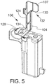
- FIG. 5 is a perspective view of an assembly including a lever and a handgun having a trigger guard.
- the handgun is cross-sectioned for purposes of illustration in FIG. 5 .
- FIG. 6 is a perspective view of an assembly including a lever and a handgun having a trigger guard.
- the handgun is cross-sectioned for purposes of illustration in FIG. 6 .
- FIG. 7 is a perspective view of an assembly including a lever and a handgun having a trigger guard.
- the handgun is cross-sectioned for purposes of illustration in FIG. 7 .
- FIGS. 8A and 8B are plan views of an assembly including a lever and a handgun having a trigger guard.
- the handgun is cross-sectioned for purposes of illustration in FIGS. 8A and 8B .
- FIG. 9 is a cross-sectioned perspective view of an assembly including a holster and a handgun having a trigger guard.
- the holster and the handgun are cross-sectioned for purposes of illustration in FIG. 9 .
- FIG. 10 is a plan view of an assembly including a holster and a handgun having a trigger guard.
- the holster and the handgun are cross-sectioned for purposes of illustration in FIG. 10 .
- FIGS. 11A-11C are stylized cross-sectional views each showing a pin and a pin receiving portion.
- FIG. 12 is a stylized cross-sectional view showing a pin and a pin receiving portion.
- FIG. 13 is a perspective view showing a pin and a pin receiving portion.
- FIG. 14 is a perspective view showing a handgun and a holster in accordance with the detailed description.
- FIG. 15 is an exploded perspective view showing a holster body and two active handgun retention mechanisms operated by a single thumb button.
- FIG. 16 is a perspective view showing retention mechanisms seen in the exploded perspective view of FIG. 15 .
- FIG. 17 is an exploded perspective view further illustrating some of the elements seen in the sub-assembly of FIG. 16 .
- FIG. 18A is a perspective view of components of handgun retention mechanisms.
- FIG. 18B is an exploded view of the components of FIG. 18A .
- FIG. 19 is a further exploded view of components of the handgun retention mechanisms including a housing for securing the pivoting thumb button.
- FIG. 20 is a further exploded view of components of the handgun retention mechanisms taken from the side opposite that of FIG. 19 .
- FIG. 21 is an exploded view of an embodiment of a holster with a with thumb button operating a single retention mechanism and a thumb button guard.
- FIG. 22 is a plan view of a holster with a holstered handgun and a user's hand about the grasp the handgun.
- FIG. 23 is a plan view of a holster with a holstered handgun and a user's hand engaging the handgun.
- FIG. 24 is a plan view of a holster with a holstered handgun and a user's hand engaging the handgun.
- FIG. 25 is a perspective view showing a holster including a hood spring, a lever spring, and a tab spring.
- a holster including a hood spring, a lever spring, and a tab spring.
- the hood spring, the lever spring, and the tab spring are each illustrated a second time at a location spaced away from the holster.
- FIG. 26 is a perspective view showing an assembly including a lever, a lever spring, a tab, and a tab spring.
- the lever spring and the tab spring are each illustrated a second time at a location spaced away from the assembly.
- FIG. 27 is a perspective view of an assembly including a lever, a lever spring, a tab, and a tab spring.
- the lever spring and the tab spring are each illustrated a second time at a location spaced away from the assembly.
- FIGS. 28A and 28B are perspective views showing an assembly including a hood assembly and a thumb receiving tab.
- FIGS. 29A and 29B are perspective views showing an assembly including a hood assembly and a thumb receiving tab.
- FIG. 30A is a plan view showing a hood assembly part having a lug portion and a thumb receiving tab having a protrusion portion that selectively engages the lug portion of the hood assembly part.
- FIG. 31A is a perspective view of the assembly shown in FIG. 30A . In the embodiments of FIGS. 30A and 31A , the hood assembly part is in a handgun retaining position.
- FIG. 30B is a plan view showing a hood assembly part having a lug portion and a thumb receiving tab having a protrusion portion that selectively engages the lug portion of the hood assembly part.
- FIG. 31B is a perspective view of the assembly shown in FIG. 30B . In the embodiments of FIGS. 30B and 31B , the hood assembly part is in a handgun releasing position.
- FIG. 32A is a perspective view showing a holster in accordance with the detailed description.
- FIG. 32B is a perspective view showing selected parts from the holster shown in FIG. 32A .
- the parts shown in FIG. 32B include a U-shaped shroud, a bracket and a finger receiving tab.
- FIG. 32C is a perspective view further illustrating the parts shown in FIG. 32B .
- the U-shaped shroud, the bracket and the finger receiving tab are shown from a different viewpoint.
- FIGS. 33A and 33B are two perspective views showing a holster including a U-shaped shroud.
- the U-shaped shroud is in a handgun retaining position.
- the U-shaped shroud is in a release position.
- FIGS. 34A and 34B are perspective views of a belt engaging member.
- FIG. 35A is a front view of the belt engaging member shown in FIGS. 34A and 34B .
- FIG. 35B is a right side view of the belt engaging member shown in FIGS. 34A and 34B .
- FIG. 35C is a top view of the belt engaging member shown in FIGS. 34A and 34B .
- FIG. 35D is a rear view of the belt engaging member shown in FIGS. 34A and 34B .
- FIG. 35E is a left side view of the belt engaging member shown in FIGS. 34A and 34B .
- FIG. 35F is a bottom view of the belt engaging member shown in FIGS. 34A and 34B .
- FIGS. 36A and 36B are two perspective views showing a holster having a first handgun retention mechanism including a pivotable lever and a second handgun retention mechanism including a U-shaped shroud.
- the U-shaped shroud is in a handgun retaining position.
- FIG. 37A is a front view of the holster shown in FIGS. 36A and 36B .
- FIG. 37B is a right side view of the holster shown in FIGS. 36A and 36B .
- FIG. 37C is a top view of the holster shown in FIGS. 36A and 36B .
- FIG. 37D is a rear view of the holster shown in FIGS. 36A and 36B .
- FIG. 37E is a left side view of the holster shown in FIGS. 36A and 36B .
- FIG. 37F is a bottom view of the holster shown in FIGS. 36A and 36B .
- FIGS. 38A and 38B are two perspective views showing a holster having a handgun retention mechanism including a pivotable lever.
- FIG. 39A is a front view of the holster shown in FIGS. 38A and 38B .
- FIG. 39B is a right side view of the holster shown in FIGS. 38A and 38B .
- FIG. 39C is a top view of the holster shown in FIGS. 38A and 38B .
- FIG. 39D is a rear view of the holster shown in FIGS. 38A and 38B .
- FIG. 39E is a left side view of the holster shown in FIGS. 38A and 38B .
- FIG. 39F is a bottom view of the holster shown in FIGS. 38A and 38B .
- FIG. 40 is an exploded perspective view showing a belt receiving member, a holster body and a lever.
- FIG. 41 is an exploded perspective view showing a holster body and a lever.
- FIG. 42 is an exploded perspective view showing a belt receiving member, a holster body and two locking mechanisms.
- FIG. 43 is an exploded perspective view showing a holster body and two locking mechanisms.
- FIG. 44 is a perspective view showing the belt receiving member, the holster body and the lever shown in FIG. 40 .
- FIG. 45 is a top view showing the belt receiving member, the holster body and the lever shown in FIG. 40 .
- FIG. 46 is a perspective view showing the belt receiving member, the holster body and the locking mechanisms shown in FIG. 42 .
- FIG. 47 is a top view showing the belt receiving member, the holster body and the locking mechanisms shown in FIG. 42 .
- FIGS. 48A and 48B are perspective views of a belt engaging member.
- FIG. 49A is a front view of the belt engaging member shown in FIGS. 48A and 48B .
- FIG. 49B is a right side view of the belt engaging member shown in FIGS. 48A and 48B .
- FIG. 49C is a top view of the belt engaging member shown in FIGS. 48A and 48B .
- FIG. 49D is a rear view of the belt engaging member shown in FIGS. 48A and 48B .
- FIG. 49E is a left side view of the belt engaging member shown in FIGS. 48A and 48B .
- FIG. 49F is a bottom view of the belt engaging member shown in FIGS. 48A and 48B .
- FIGS. 50A and 50B are two perspective views showing a holster having a first handgun retention mechanism including a pivotable lever and a second handgun retention mechanism including a U-shaped shroud.
- the U-shaped shroud is in a handgun retaining position.
- FIG. 51A is a front view of the holster shown in FIGS. 50A and 50B .
- FIG. 51B is a right side view of the holster shown in FIGS. 50A and 50B .
- FIG. 51C is a top view of the holster shown in FIGS. 50A and 50B .
- FIG. 51D is a rear view of the holster shown in FIGS. 50A and 50B .
- FIG. 51E is a left side view of the holster shown in FIGS. 50A and 50B .
- FIG. 51F is a bottom view of the holster shown in FIGS. 50A and 50B .
- FIGS. 52A and 52B are two perspective views showing a holster having a handgun retention mechanism including a pivotable lever.
- FIG. 53A is a front view of the holster shown in FIGS. 52A and 52B .
- FIG. 53B is a right side view of the holster shown in FIGS. 52A and 52B .
- FIG. 53C is a top view of the holster shown in FIGS. 52A and 52B .
- FIG. 53D is a rear view of the holster shown in FIGS. 52A and 52B .
- FIG. 53E is a left side view of the holster shown in FIGS. 52A and 52B .
- FIG. 53F is a bottom view of the holster shown in FIGS. 52A and 52B .
- FIGS. 1-4 perspective views of a handgun 80 and a holster 100 are shown.
- FIG. 1 shows the handgun 80 withdrawn from the holster 100
- FIG. 2 shows the handgun inserted into the holster 100 .
- the handgun being conventional and having a forward end 82 , a handgun body 84 , a grip 86 at a rearward end 87 of the handgun 80 , a trigger guard 90 , a back strap 92 with a backstrap recess 94 , a slide 98 positioned above the handgun body, and a rail 99 positioned below the slide.
- the holster 100 for receiving and withdrawing the handgun having a trigger guard 90 comprises a polymer holster body 102 , an elongate polymer pivoting lever 104 that is part of a first handgun retention mechanism 106 that is thumb actuated.
- the pivoting lever has an actuation tab 107 configured as by a thumb receiving button that is disposed in an opening 105 in the holster body, actuation of the thumb receiving button moves a trigger guard block portion 128 of the lever between retention and release positions.
- the retention mechanism 106 has two distinct separated pivoting connections 109 each formed from a pair of cooperating connector pivot portions 110 , one of each pair unitary with the holster body and the other of each pair unitary with the lever.
- the pivot portions 110 of the lever 104 and pivot portions 110 of the holster body 102 are coupled using a simple assembly process with no separate hinge pin.
- the holster body has three unitary bosses 111 on a proximal wall portion 113 for attachment to a plate portion of a user attachment means, such as a belt engaging member. See FIGS. 12 and 13 .
- the holster having a proximal side toward and holster body having a proximal
- the holster body 102 has a plurality of holster wall portions defining a cavity 108 extending along a handgun receiving and withdrawal axis 110 H.
- the retention mechanism 106 comprises a lever 104 pivotally supported by the holster body 102 and retained by holster attachment plate portion 165 or by other means.
- the lever 104 may comprise an elongate central portion 124 integrally formed with a first forward pivot portion 112 and the holster body 102 may comprises a second forward pivot portion 114 integrally formed with one of the holster wall portions.
- the first forward pivot portion 112 may mate with the second forward pivot portion 114 to form a forward pivoting connection 109 .
- the lever 104 further comprises a first rearward pivot portion 116 integrally formed with the elongate central portion 124 of the lever 104 and the holster body 102 comprises a second rearward pivot portion 118 integrally formed with one of the holster wall portions.
- the first rearward pivot portion 116 may mate with the second rearward pivot portion 118 to form a rearward pivoting connection 109 .
- all pivot portions of the retention mechanism are axially aligned and co-axial when assembled.
- the retaining mechanism has a lever that can be pivoted with little tension in the muscles and tendons of the forearm and thumb while the forearm is extending in a downward direction and the thumb is contacting the a thumb button portion of the lever.
- the retaining mechanism comprises a lever having a thumb button portion, and the lever pivots about an axis that is parallel to a handgun insertion and withdrawal axis of the holster.
- the retaining mechanism comprises a thumb-actuated button that pivots about a first axis and a lever that pivots about a second axis that is parallel to the first axis.
- the lever 104 of the retention mechanism 106 has an elongate central portion 124 , a thumb receiving portion 107 , configured as a thumb button, and a blocking portion 108 .
- the thumb receiving portion of the lever comprising a first arm 130 extending away from the elongate central portion 124 in a first direction, the elongate central portion 124 and the first arm 130 cooperating to form a first L-shaped portion 132 .
- the blocking portion 128 of the lever 104 comprises a second arm 134 extending away from the elongate central portion 124 in a second direction opposite the first direction, the elongate central portion 124 and the second arm 134 cooperating to form a second L-shaped portion 136 .
- the lever 104 is elongate in the direction of the axis X and has a lever length L 1 .
- the pivot portions 112 , 116 have a separation distance D 1 and have a pivoting connection length L 2 .
- the pivoting connection length L 2 to the overall lever length L 1 is in embodiments greater than 0.70 or 70%; in embodiments, greater than 0.60 or 60%; in embodiments greater than 0.80 or 80%.
- a forward or handgun insertion direction Z and a rearward or handgun withdrawal direction ⁇ Z are illustrated using arrows labeled “Z” and “ ⁇ Z,” respectively.
- An upward direction Y and a downward direction ⁇ Y are illustrated using arrows labeled “Y” and “ ⁇ Y,” respectively.
- a direction X extending away from the user's body and the user attachment side of the holster is illustrated using an arrow labeled “X.”
- a direction ⁇ X extending toward the user's body and the user attachment side of the holster is illustrated using an arrow labeled “ ⁇ X.”
- the directions illustrated using these arrows may be conceptualized, by way of example and not limitation, from the point of view of a user who is wearing a holster hung from a service belt and inserting a handgun into the holster.
- the directions illustrated using these arrows may also be conceptualized, by way of example and not limitation, from the point of view of a user holding a handgun in a normal firing position and viewing the gunsights of the handgun.
- the Z direction and the ⁇ Z direction are both generally orthogonal to the XY plane defined by the X direction and the Y direction.
- the X direction and the ⁇ X direction are both generally orthogonal to the ZY plane defined by the Z direction and the ⁇ Z direction.
- the Y direction and the ⁇ Y direction are both generally orthogonal to the ZX plane defined by the Z direction and the X direction.
- Various direction-indicating terms are used herein as a convenient way to discuss the objects shown in the figures. It will be appreciated that many direction indicating terms are related to the instant orientation of the object being described.
- the holster body 102 is formed from two polymers, one overmolded onto the other, providing an interior layer 138 and an exterior layer 140 .
- the interior layer 138 is softer than the exterior layer 140 minimizing any wear, damage or markings on the exterior surface of the handgun that is received in the cavity 108 defined by the holster.
- the interior layer 138 and the exterior layer 140 are combined using an assembly process.
- the interior layer 138 comprises a thermoplastic elastomer (TPE) and the exterior layer 140 a thermoplastic material.
- the interior layer 138 comprises Hytrel® polymer, available from DuPont, and the exterior layer 140 comprises nylon. The exterior layer being harder and stiffer than the interior layer.
- a cross-sectional view of a holster body 102 is shown.
- the holster body 102 is formed to provide a handgun fitting function that can be adjusted by rotating a tensioning screw 142 .
- the shape of the forward portion of the handgun can be conceptualized as a four cornered geometric figure, roughly a rectangle, and the shape of the cavity 108 defined by the holster body 102 can be configured to make point contact with the four corners of the figure or rectangle.
- the shape of the cavity 108 defined by the holster body 102 can be conceptualized as two opposing V-shapes, an upper V-shape 148 and a lower V-shape 146 .
- the upper V-shape 148 and the lower V-shape 146 are shown using dashed lines in FIG. 10 .
- the two legs of the upper V-shape 148 and the two legs of the lower V-shape 146 may each contact one corner of the figure or rectangle.
- the lower V-shape 146 defines a slot 144 near the lower end of the lower V-shape 146 .
- a tensioning screw 142 is positioned to selectively decrease the angle between the two legs of the lower V-shape 146 .
- the two legs of the lower V-shape 146 apply upwardly directed component forces to two lower corners 150 of the rectangle.
- the forces applied to the lower corners 150 of the rectangle urge the two upper corners 152 of the rectangle against the two legs of the upper V-shape 148 .
- the components herein may be formed of thermoplastic polymers using an injection molding process.
- a retention mechanism 106 for a holster 100 may include a lever pivotally supported by the holster body 102 .
- the lever 104 may comprise an elongate central portion 124 integrally formed with a first forward pivot portion 112
- the holster body 102 may comprise a second forward pivot portion 114 integrally formed with a wall portion of the holster body 102 .
- the first forward pivot portion 112 may be mated with the second forward pivot portion so that the lever 104 is pivotally supported by the holster body 102 .
- one of the forward pivot portions 112 , 114 is a pin portion 154 and the other of the forward pivot portions 112 , 114 is a C-shaped pin receiving portion 156 .
- the C-shaped pin receiving portion 156 has a circumferential span less than or equal to 180 degrees.
- the C-shaped pin receiving portion 156 has a circumferential span greater than 180 degrees; in embodiments greater than 185°; and in embodiments greater than 190°.
- one of the forward pivot portions 112 , 114 is a pin portion 154 and the other of the forward pivot portions 112 , 114 is a U-shaped pin receiving portion 158 .
- the lever 104 may further comprise a first rearward pivot portion 116 integrally formed with the elongate central portion 124 and the holster body 102 may comprise a second rearward pivot portion 118 integrally formed with a wall portion of the holster body 102 .
- the first rearward pivot portion 116 may be mated with the second rearward pivot portion so that the lever 104 is pivotally supported by the holster body 102 .
- one of the rearward pivot portions 116 , 118 is a pin portion 154 and the other of the rearward pivot portions 116 , 118 is a C-shaped pin receiving portion 156 .
- the C-shaped pin receiving portion 156 has a circumferential span less than or equal to 180 degrees. In embodiments, the C-shaped pin receiving portion 156 has a circumferential span greater than 180 degrees; in embodiments greater than 185°; and in embodiments greater than 190°. In embodiments, one of the rearward pivot portions 116 , 118 is a pin portion 154 and the other of the rearward pivot portions 116 , 118 is a U-shaped pin receiving portion 158 .
- a holster 100 in accordance with this detailed description may comprise a holster attachment plate portion 165 that is part of or all of a user attachment means for the holster which may be a belt engaging member.
- the plate portion 165 may retain the lever 104 in a pivoting connection arrangement with the holster body 102 .
- the lever 104 may be pivotally supported by the holster body 102 and may be moveable between a handgun trigger guard capture position and a handgun trigger guard release position.
- the plate portion 165 is fixed to the holster body 102 by a plurality of screws 162 .
- the lever 104 may be, for example, captured between the belt engaging member 160 , or other user attachment means, and the holster body 102 . In embodiments, the lever 104 can be freely separated from the holster body 102 after the belt engaging member 160 is removed from the holster body 102 .
- the belt engaging member 160 comprises a first belt loop portion 164 defining a first passageway 166 to receive a belt and a second belt loop portion 168 defining a second passageway 170 for receiving the belt.
- the user attachment means 160 may comprise various holster supporting devices without deviating from the spirit and scope of this detailed description. Examples of holster supporting devices that may be suitable in some applications are disclosed in the following United States Patents all of which are hereby incorporated by reference herein: U.S. Pat. Nos.
- a holster 100 has a first handgun retention mechanism 106 ′ that engages the trigger guard as previously described with respect to FIGS. 1-13 , and a second handgun retention mechanism 106 ′ with a pivoting lever 104 ′.
- a dual actuation member 179 with a thumb button 180 actuates both the first handgun retention mechanism 106 ′ and the second handgun retention mechanism 174 .
- each handgun retention mechanism selectively prevents the handgun 80 from being withdrawn from the cavity 108 defined by the wall portions 109 of the holster body 102 .
- the second handgun retention mechanism 106 ′ comprises a slide retention member configured as a U-shaped shroud 176 that is pivotally supported by the holster body 102 so that the U-shaped shroud 176 selectively pivots between a handgun retaining position in which the U-shaped shroud 176 extends across a portion of a rearward opening 178 of the cavity 108 and a release position in which the U-shaped shroud 176 extends forward of the rearward opening 178 so that a withdrawal path of the handgun 80 is unobstructed.
- the U-shaped shroud 176 pivots about a shroud pivot axis 177 that extends laterally and is perpendicular to the handgun insertion and withdrawal axis.
- the first handgun retention mechanism 106 ′ comprises a lever 104 ′ pivotally supported by the holster body 102 .
- the lever 104 ′ may be similarly configured to the lever 106 of FIGS. 1-13 .
- the lever 104 ′ has an elongate central portion 124 , a depressible actuation portion 186 , and a trigger guard blocking portion 128 .
- the depressible actuation portion 186 of the lever 104 comprises a first arm 130 extending away from the elongate central portion 124 in a first direction so that the elongate central portion 124 and the first arm 130 cooperate to form a first L-shape 182 .
- the trigger guard blocking portion 128 of the lever 104 ′ comprises a second arm 134 extending away from the elongate central portion 124 in a second direction opposite the first direction so that the elongate central portion 124 and the second arm 134 cooperate to form a second L-shape 184 .
- the lever 104 ′ is pivotally supported by the holster body so that the lever 104 ′ pivots about a lever axis 110 that extends in upward and downward directions as the holster is worn or forward and rearward with respect to the handgun.
- the lever pivots between a handgun trigger guard blocking or capture position and a handgun trigger guard non-blocking or release position.
- the trigger guard blocking portion 128 of the lever 104 extends into a trigger guard portion of the holster body 102 when the lever 104 ′ is disposed in the handgun trigger guard capture position.
- a feature and benefit of embodiments is a retention mechanism having a lever that can be pivoted with little tension in the muscles and tendons of the forearm and thumb while the forearm is extending in a downward direction and the thumb is used to rotate the lever.
- the retaining mechanism comprises a thumb-actuated button that pivots about a first axis and a lever that pivots about a second axis that is parallel to the first axis.
- the lever pivots about an axis that is parallel to a handgun insertion and withdrawal axis of the holster.
- the thumb-actuated button pivots about an axis that is parallel to a handgun insertion and withdrawal axis of the holster.
- the slide blocking member configured as a shroud 176 is part of a hood assembly 188 .
- Fasteners 197 , 198 pivotally secure the U-shaped shroud, second handgun retention mechanism housing 201 , bracket 190 with slot 144 , to the holster body.
- Fastener 199 secures the opposite side of the shroud to the holster body.
- the second handgun retention mechanism 174 utilizes the retention mechanism housing 201 to secure components of the retention mechanism in place.
- the housing has two cooperating components, and inward member 202 and an outward member 204 , that may be arranged in a clamshell-like fashion that captures the leaf spring 194 and a pivoting shaft 206 of the dual actuation member 179 within the housing 201 .
- the holster includes a spring 196 that biases the U-shaped shroud 176 to pivot toward the release position.
- the holster 100 includes the leaf spring 194 that is received in the slot 144 of the bracket 190 when the U-shaped shroud 176 is in the handgun retaining position.
- the base 195 of the leaf spring 194 is fixed with respect to the holster body and the tip 196 of the leaf spring 194 can flex inwardly and outwardly.
- the bracket 190 is attached to the U-shaped shroud 176 such that as the leaf spring 194 keeps the bracket from rotating forwardly it also keeps the shroud from rotating forwardly.
- rotation of the thumb receiving tab or button 180 through a first range of rotary motion causes deflection of the leaf spring 194 so that a distal portion of the leaf spring 194 moves outside of the slot 144 allowing the bracket 190 and also the shroud 176 to rotate forwardly.
- rotation of the thumb button 180 through a second range of rotary motion causes the thumb button 180 to engage the depressible actuation portion 186 of the lever 104 causing at least part of the trigger guard blocking portion 128 of the lever to be withdrawn from the trigger guard receiving portion of the holster body 102 .
- the thumb receiving portion of the lever 104 of the embodiment of FIGS. 1-4 has been replaced with an actuation portion or depressible portion that is depressed by the inner side of the thumb receiving tab 180 .
- the first and second active handgun retention mechanisms may be arranged such that the second and first mechanisms can actuate sequentially or simultaneously, in embodiments.
- FIG. 21 another embodiment of a holster 300 comprising a holster body 306 similar to that of FIGS. 14 and 15 with a top or forward wall portion that mostly covers the slide of a handgun holstered therein, a pair of bosses 310 that can receive components of a second active handgun retention mechanism or, as illustrated in FIG. 21 , a removable thumb button guard 312 secured to the bosses with fasteners 316 .
- the lever 104 may be configured as discussed previously with respect to FIGS. 1-9 and has a thumb button 180 .
- the plate portion 165 of a belt engaging member may capture the pivoting lever onto the holster body.
- FIGS. 22-24 the sequence of gripping and drawing a handgun 80 from a holster 100 having a optimally positioned thumb button 107 is illustrated.
- the handgrip a of the handgun 80 has a backstrap 322 region with a backstrap recess 324 that receives the user's hand 340 initially by the webbing 342 of the hand contacting the recess 324 .
- the user will then wrap his middle, ring, and pinky fingers 350 , 351 , 352 around the grip as shown in FIG. 23 and will have his forefinger 353 in a longitudinal recess for said finger on the side of the holster opposite the thumb button.
- the thumb 354 will naturally be positioned at the thumb button 107 such that a normal grasping action of the grip, consistent with the “master grip” will depress the thumb button 107 and actuate the retention mechanism 104 .
- the master grip and ergonomics are further facilitated in embodiments where the thumb button 180 is positioned with no holster body directly rearward of the rearward margin of the thumb button 180 , as well as no holster body portions below the thumb button 180 .
- the thumb button 180 In use, as the handgun 80 is gripped prior to actuation of the thumb button 180 , the user's thumb is in the natural gripping position at the surface of the thumb button 180 , the thumb button 180 is depressed, coincident with grasping the handgun 80 , and as the handgun 80 is withdrawn, the user's thumb slides off of the thumb button 180 into immediate contact with the handgun 80 . That is, there is no engagement with the exterior surface of the holster body 102 by the user's thumb either during actuation of the release of the retention mechanism or as the handgun 80 is withdrawn. In that the thumb button 180 is positioned in close proximity to the surface of the handgun 80 , the thumb movement inward as the thumb transitions from engagement with the thumb button 180 to engagement with the body of the handgun 80 is minimal.
- the holster includes the hood spring 196 , a lever spring 198 and a tab spring 200 .
- each spring comprises a length of wire 206 , the wire 206 of the spring forming a first leg 208 , a second leg 210 and a coil 212 disposed between the first leg 208 and the second leg 210 .
- the first leg 208 of the hood spring 196 is fixed relative to the holster body 102 and the second leg 210 of the hood spring 196 is seated against the hood assembly 188 so that the U-shaped shroud 176 is biased to pivot toward the release position.
- the lever spring 198 is positioned and adapted to bias the lever 104 to rotate toward the handgun trigger guard capture position.
- the first leg 208 of the lever spring 198 is seated against to the holster body 102 and the second leg 210 of the lever spring 198 is seated against the lever 104 .
- the tab spring 200 is positioned and adapted to bias the thumb receiving tab 180 to rotate in a direction that moves a distal end of the thumb receiving tab 180 away from the holster body 102 .
- the first leg 208 of the tab spring 200 is seated against to the holster body 102 and the second leg 210 of the tab spring 200 is seated against the thumb receiving tab 180 .
- the U-shaped shroud 176 is part of a hood assembly 188 .
- a bracket 190 of the hood assembly 188 includes a lug portion 214 and the thumb receiving tab 180 includes a protrusion portion 216 that engages the lug portion 214 of the hood assembly 188 while the U-shaped shroud 176 is in the handgun retaining position.
- the holster 100 further includes a hood spring 196 that biases the U-shaped shroud 176 to pivot toward the release position.
- the hood spring 196 biases the lug portion 214 of the hood assembly 188 against the protrusion portion 216 of the thumb receiving tab 180 while the U-shaped shroud 176 is in the handgun retaining position.
- rotation of the thumb receiving tab 180 through a first range of rotary motion causes the protrusion portion 216 of the thumb receiving tab 180 to disengage from the lug portion 214 of the hood assembly 188 .
- rotation of the thumb receiving tab 180 through a second range of rotary motion causes the thumb receiving tab 180 to engage the tab receiving portion of the lever 104 causing at least a portion of the trigger guard retaining portion of the lever 104 to be withdrawn from the trigger guard receiving portion of the holster body 102 .
- a feature and benefit of embodiments is a retention mechanism having a lever 104 that can be pivoted with little tension in the muscles and tendons of the forearm and thumb while the forearm is extending in a downward direction and the thumb is contacting a thumb receiving tab 180 .
- the retaining mechanism comprises a thumb receiving tab 180 that pivots about a first axis and a lever 104 that pivots about a second axis that is parallel to the first axis.
- the lever 104 pivots about an axis that is parallel to a handgun insertion and withdrawal axis 110 H of the holster 100 .
- FIGS. 33A and 33B are two perspective views showing a holster including a U-shaped shroud.
- the U-shaped shroud is in a handgun retaining position.
- the U-shaped shroud is in a release position.
- an exteriorly worn holster 100 for receiving a handgun 80 has a holster body 102 having a plurality of unitary holster wall portions defining a handgun receiving cavity 108 and a rearward opening 88 .
- the handgun has a handgun body 84 , a handgrip 86 , a slide 98 , and a trigger guard 90 .
- the holster body 102 has a handgun receiving and withdrawal axis 110 H.
- the plurality of holster wall portions comprise a user proximal wall portion 113 and a user distal wall portion 115 , the proximal wall portion 113 having thumb button recess 218 with a thumb button recess edge portion 220 defining the thumb button recess 218 .
- the thumb button recess 218 extends forwardly from the rearward opening 88 .
- a first user actuatable handgun retention mechanism 106 of the holster 100 is located at the proximal wall portion 113 for selectively preventing the handgun 80 , when in the cavity 108 , from being withdrawn from the cavity 108 .
- the first handgun retention mechanism 106 comprises a first lever 104 pivotally mounted on the proximal wall portion 113 of the holster body 102 with a first axis of rotation.
- the first lever 104 has an actuation tab 107 rearwardly positioned on the lever 104 and positioned within the thumb button recess 218 .
- the actuation tab 107 has an upper margin 222 , a rearward margin 224 , and a lower margin 226 .
- the lever 104 further has a trigger guard blocking portion 128 forwardly positioned on the lever 104 , the lever 104 being configured and positioned such that depression of the actuation tab 107 rotates the lever 104 about its respective axis of rotation to move the trigger guard blocking portion 128 from a trigger guard blocking position to a non-blocking position.
- an upper portion 242 of the thumb button recess edge portion 220 extends rearwardly of the actuation tab 107 along the upper margin 222 of the actuation tab 107 and a lower portion 246 of the thumb button recess edge portion 220 extends rearwardly of the actuation tab 107 at the lower margin 226 of the actuation tab 107 .
- the holster 100 has only a single user actuatable handgun retention mechanism 106 and the actuation tab is configured as an actuation tab 107 .
- the holster 100 comprises a pair of thumb guides 230 positioned above and below the actuation tab 107 , the thumb guides 230 projecting laterally outward from the holster body proximal wall portion 113 beyond an undepressed position of the actuation tab 107 .
- the thumb guides 230 each extend laterally outward from an outward surface of the proximal wall portion 113 a distance of at least 0.35 inches.
- the holster 100 has a second handgun retention mechanism 174 including a pivoting shroud 176 positioned rearwardly of the slide 98 of the handgun 80 holstered in the holster 100 .
- the second handgun retention mechanism 174 comprises a second lever 104 ′, the second lever 104 ′ having an actuation tab configured as a thumb button 180 , the actuation tab of the first lever position behind the thumb button 180 whereby depression of the thumb button 180 also depresses the actuation tab of the first lever.
- the holster 100 further comprises a pair of thumb guides 230 positioned above and below the thumb button 180 , the thumb guides 230 projecting laterally outward from the holster body 102 proximal wall portion 113 beyond an undepressed position of the thumb button 180 .
- one of the thumb guides 230 is positioned above the thumb button 180 and comprises a housing for the second handgun retention mechanism 174 .
- a belt engaging member 160 is attached to the holster body 102 with a plurality of threaded fasteners 162 extending into the holster body 102 .
- one of said threaded fasteners 162 is positioned above the first lever 104 , one of the plurality of threaded fasteners 162 is positioned below the first lever 104 , and one of the plurality of threaded fasteners 162 is positioned forward of the first lever 104 , wherein the first lever 104 is captured between the holster body 102 and the belt engaging member 162 .
- a column portion of the belt engaging member 160 extends rearwardly, wherein when the handgun 80 is holstered.
- the thumb button 180 is positioned between the handgun body 84 and the belt engaging member 160 , wherein the belt engaging member 160 has a pair of ribs 232 having their elongate dimension extending forwardly and rearwardly and positioned to confront the thumb guides 230 whereby access to the thumb button 180 is restricted on four sides of the thumb button 180 and an access path for the thumb is provided rearwardly of the thumb button 180 .
- the belt engaging member 160 comprises a jacket slot belt loop 228 having a pair of clamping belt loop portions 234 extending from the column portion 236 , each of the clamping belt loop portions 234 being adjustable with respect to the column portion 236 by a respective threaded fastener 262 .
- the thumb guides 230 each extend laterally outward from an outward surface of the proximal wall portion 113 a distance of at least 0.35 inches. In embodiments, the thumb guides 230 each extend laterally outward from an outward surface of the proximal wall portion 113 a distance of at least 0.35 inches and the ribs 232 extend outwardly from a surface of the column portion 236 a distance of at least 0.15 inches.
- the first lever 104 is seated in a lever receiving region 238 on the proximal wall portion 113 of the holster body and the proximal wall portion 113 has three threaded bosses 240 dispersed around the lever receiving region 238 for receiving a belt engaging member 160 .
- the proximal wall portion 113 further has a plurality of lever region containment wall portions 244 extending from the outer surface of the proximal wall portion 113 and each of the plurality of lever containment wall portions 244 connect to at least one of the three threaded bosses 240 .
- the three threaded bosses 240 are positioned for receiving a belt engaging member 160 utilizing a plurality of threaded fasteners 162 .
- the first lever 104 is seated in a lever receiving region 238 on the proximal wall portion 113 and the proximal wall portion 113 has three threaded bosses 240 dispersed around the lever receiving region 238 for receiving a belt engaging member 160 and, when the belt engaging member 160 is attached, the first lever 104 is captured within the lever receiving region 238 .
- the first lever 104 may be removed from an engagement with the proximal wall portion 113 when the belt engaging member is not attached to the proximal wall portion 113 .
- the first lever 104 may be removed without tools when the belt engaging member is not attached.
- the first lever 104 may be removed by simply prying the first lever 104 outward when the belt engaging member 160 is not attached.
- the holster body 102 has an upper wall portion having a pair of inclined wall portions defining a joint, a lower wall portion with a slit 250 extending from a forward opening to proximate a trigger guard receiving portion of the holster body defining a pair of forward clamping wall portions 248 .
- a threaded fastener 142 is positioned so as to extend between the pair of forward clamping wall portions 248 for adjusting the forward clamping wall portions 248 about a forward portion of the handgun 80 .
- a holster 100 is provided for receiving a handgun 80 having a handgun body 84 , a slide 98 , and a trigger guard 90 .
- the holster 100 comprises a holster body 102 having a plurality of holster wall portions defining a rearward opening cavity 108 extending along a handgun receiving and withdrawal axis 110 H for receiving and holding the handgun 80 .
- the plurality of holster wall portions comprise a user proximal wall portion 113 and a user distal wall portion 115 .
- the holster includes a first handgun retention mechanism 106 ′ and a second handgun retention mechanism 174 , disposed at the proximal wall portion 113 , each handgun retention mechanism selectively preventing the handgun 80 , when in the cavity 108 , from being withdrawn from the cavity 108 .
- the first and second handgun retention mechanisms have a respective first lever 104 ′ having a first axis of rotation and a second lever 180 with an axis of rotation, each lever having a respective actuation tab portion on one end of the lever where depression of the actuation tab rotates the lever about its respective axis of rotation, one of the two actuation tabs configured as a thumb receiving button with an outer thumb receiving surface, the other of the two actuation tabs positioned behind the thumb receiving button such that depression of the thumb receiving button effects a depression of the other of the two actuation tab portions, whereby depression of the thumb receiving button actuates both the first handgun retention mechanism 106 ′ and the second handgun retention mechanism 174 .
- the first lever 104 ′ of the first handgun retention mechanism 106 ′ is pivotally supported by the holster body 102 .
- the first lever 104 ′ comprises an elongate central portion 124 and a blocking portion 128 at an end opposite the respective actuation tab, the blocking portion 128 movable in and out of a handgun blocking position.
- the second handgun retention mechanism 174 comprising a U-shaped member 176 that is pivotally supported by the holster body 102 so that the U-shaped member 176 selectively pivots between a handgun retaining position in which the U-shaped member extends across a portion of a rearward opening of the cavity 108 and a release position in which the U-shaped member 176 is displaced from the portion of the rearward opening so that a withdrawal path of the handgun 80 is unobstructed by U-shaped member 176 .
Abstract
Description
Claims (20)
Priority Applications (7)
| Application Number | Priority Date | Filing Date | Title |
|---|---|---|---|
| US16/364,141 US10619974B2 (en) | 2018-03-23 | 2019-03-25 | Thumb-actuated locking holster |
| US16/748,151 US10996024B2 (en) | 2018-03-23 | 2020-01-21 | Thumb-actuated locking holster |
| US16/747,986 US11002511B2 (en) | 2018-03-23 | 2020-01-21 | Thumb-actuated locking holster |
| US17/245,688 US11725905B2 (en) | 2018-03-23 | 2021-04-30 | Thumb-actuated locking holster |
| US17/315,425 US11506466B2 (en) | 2018-03-23 | 2021-05-10 | Thumb-actuated locking holster |
| US17/988,039 US20230121728A1 (en) | 2018-03-23 | 2022-11-16 | Thumb-actuated locking holster |
| US18/216,981 US20240035776A1 (en) | 2018-03-23 | 2023-06-30 | Thumb-actuated locking holster |
Applications Claiming Priority (5)
| Application Number | Priority Date | Filing Date | Title |
|---|---|---|---|
| US201862647265P | 2018-03-23 | 2018-03-23 | |
| US29/647,062 USD860641S1 (en) | 2018-05-09 | 2018-05-09 | Holster |
| US201862712717P | 2018-07-31 | 2018-07-31 | |
| US201962794594P | 2019-01-19 | 2019-01-19 | |
| US16/364,141 US10619974B2 (en) | 2018-03-23 | 2019-03-25 | Thumb-actuated locking holster |
Related Parent Applications (1)
| Application Number | Title | Priority Date | Filing Date |
|---|---|---|---|
| US29/647,062 Continuation USD860641S1 (en) | 2018-03-23 | 2018-05-09 | Holster |
Related Child Applications (3)
| Application Number | Title | Priority Date | Filing Date |
|---|---|---|---|
| US29/721,548 Continuation USD1022789S1 (en) | 2020-01-21 | Belt loop | |
| US16/748,151 Continuation-In-Part US10996024B2 (en) | 2018-03-23 | 2020-01-21 | Thumb-actuated locking holster |
| US16/747,986 Continuation US11002511B2 (en) | 2018-03-23 | 2020-01-21 | Thumb-actuated locking holster |
Publications (2)
| Publication Number | Publication Date |
|---|---|
| US20190293386A1 US20190293386A1 (en) | 2019-09-26 |
| US10619974B2 true US10619974B2 (en) | 2020-04-14 |
Family
ID=67986599
Family Applications (3)
| Application Number | Title | Priority Date | Filing Date |
|---|---|---|---|
| US16/364,141 Active US10619974B2 (en) | 2018-03-23 | 2019-03-25 | Thumb-actuated locking holster |
| US16/747,986 Active US11002511B2 (en) | 2018-03-23 | 2020-01-21 | Thumb-actuated locking holster |
| US17/315,425 Active US11506466B2 (en) | 2018-03-23 | 2021-05-10 | Thumb-actuated locking holster |
Family Applications After (2)
| Application Number | Title | Priority Date | Filing Date |
|---|---|---|---|
| US16/747,986 Active US11002511B2 (en) | 2018-03-23 | 2020-01-21 | Thumb-actuated locking holster |
| US17/315,425 Active US11506466B2 (en) | 2018-03-23 | 2021-05-10 | Thumb-actuated locking holster |
Country Status (10)
| Country | Link |
|---|---|
| US (3) | US10619974B2 (en) |
| EP (2) | EP4220067A3 (en) |
| CN (2) | CN115790268A (en) |
| AU (1) | AU2019237543A1 (en) |
| CA (1) | CA3094826A1 (en) |
| CO (1) | CO2020013075A2 (en) |
| ES (1) | ES2948318T3 (en) |
| IL (1) | IL277459B (en) |
| MX (1) | MX2020009884A (en) |
| WO (1) | WO2019183643A1 (en) |
Cited By (10)
| Publication number | Priority date | Publication date | Assignee | Title |
|---|---|---|---|---|
| USD919964S1 (en) * | 2019-02-12 | 2021-05-25 | Edge-Works Manufacturing Company | Leverage arm for a holster or ammunition holder |
| US11105583B1 (en) * | 2017-07-17 | 2021-08-31 | Vista Outdoor Operations Llc | Holster system with removable sight cover |
| US11209240B2 (en) * | 2019-03-14 | 2021-12-28 | Tedder Industries, LLC | Duty holster |
| USD945152S1 (en) * | 2021-01-31 | 2022-03-08 | Shenzhen Tactop Industrial Co., LTD | Magnetic holder for pistol |
| EP4008989A1 (en) | 2020-12-04 | 2022-06-08 | Vista Outdoor Operations LLC | Locking holster system |
| WO2022256105A3 (en) * | 2021-05-06 | 2023-02-09 | Gary Coonan | Handgun improvement device |
| USD999519S1 (en) | 2021-06-17 | 2023-09-26 | Concealment Express, LLC | Holster with accessory receiving holes |
| USD1000108S1 (en) | 2021-02-23 | 2023-10-03 | Concealment Express, LLC | Backer with triangle pattern |
| USD1004953S1 (en) | 2021-02-23 | 2023-11-21 | Concealment Express, LLC | Angled belt loop clip |
| USD1022471S1 (en) | 2021-02-23 | 2024-04-16 | Concealment Express, LLC | Horizontal magazine belt clip |
Families Citing this family (4)
| Publication number | Priority date | Publication date | Assignee | Title |
|---|---|---|---|---|
| EP3601930A4 (en) * | 2017-03-26 | 2021-01-13 | Sentry Solutions Products Group LLC | Overmolded/through-molded holster |
| US10598462B2 (en) * | 2018-02-15 | 2020-03-24 | Tedder Industries, LLC | Pocket holster |
| US11162759B1 (en) | 2019-11-12 | 2021-11-02 | Samsun Yurt Savunma Sanayi Ve Ticaret Anonim Sirket | Lock system for holsters |
| SE2130198A1 (en) * | 2021-07-13 | 2023-01-14 | No Ordinary Company AB | Holster |
Citations (193)
| Publication number | Priority date | Publication date | Assignee | Title |
|---|---|---|---|---|
| US1046912A (en) | 1912-04-27 | 1912-12-10 | George M Wanee | Gun-holder. |
| US1113530A (en) | 1914-03-16 | 1914-10-13 | Francis H Audley | Gun-holster. |
| US1148935A (en) | 1915-02-20 | 1915-08-03 | Delbert H Snavely | Holster. |
| US1421578A (en) | 1921-03-25 | 1922-07-04 | Schussler Joseph | Safety revolver holster |
| US1635984A (en) | 1925-02-07 | 1927-07-19 | William S Swift | Revolver holster |
| US1641439A (en) | 1925-08-07 | 1927-09-06 | John B Jovino | Safety holster |
| US1750139A (en) | 1928-02-15 | 1930-03-11 | William S Swift | Revolver holster |
| US1851352A (en) | 1930-05-21 | 1932-03-29 | H & D Folsom Arms Co | Pistol holster |
| US1951865A (en) | 1931-10-22 | 1934-03-20 | H & D Folsom Arms Company | Quick release pistol holster |
| US2051844A (en) | 1935-01-15 | 1936-08-25 | Samuel G Green | Pistol holster |
| US2088811A (en) | 1936-03-16 | 1937-08-03 | Clifford A Ray | Revolver holster |
| US2109734A (en) | 1936-10-14 | 1938-03-01 | Preneta Joseph | Gun holster |
| US2349376A (en) | 1942-03-13 | 1944-05-23 | Frederick A Ray | Safety latch for pistol holsters |
| US2443397A (en) | 1945-06-06 | 1948-06-15 | William J Myres | Natural draw holster |
| US2551913A (en) | 1948-11-23 | 1951-05-08 | Keyston Bros | Retainer latch for pistol holsters |
| US2577869A (en) | 1949-10-24 | 1951-12-11 | Sumner W Adams | Pistol holster |
| US2893615A (en) | 1957-05-23 | 1959-07-07 | John R Couper | Pistol holster |
| US3289903A (en) | 1965-12-23 | 1966-12-06 | Peter J Taormina | Safety gun holster |
| US3419728A (en) | 1965-08-10 | 1968-12-31 | Curtis L. Wilson | Weapon holster |
| US3420420A (en) | 1967-05-31 | 1969-01-07 | Bucheimer Clark Leather Goods | Holster for revolver |
| US3550821A (en) | 1969-05-21 | 1970-12-29 | Andrew G Daigle | Side arm belt support |
| US3550822A (en) | 1968-12-26 | 1970-12-29 | James A Lloyd | Hand gun holster |
| US3669325A (en) | 1971-04-26 | 1972-06-13 | Ben R Furman | Quick draw holster |
| US3718240A (en) | 1971-10-28 | 1973-02-27 | P Rose | Holster with pistol retaining mechanism |
| US3777952A (en) | 1972-01-03 | 1973-12-11 | Seventrees Ltd | Secure holster for revolvers |
| US3804306A (en) | 1972-06-08 | 1974-04-16 | S Azurin | Automatic pistol holster |
| US3828990A (en) | 1972-12-27 | 1974-08-13 | A Baldocchi | Holster for pistols |
| US3866811A (en) | 1973-04-16 | 1975-02-18 | Robert L Hamby | Holster safety clasp |
| US3904091A (en) | 1974-09-13 | 1975-09-09 | H Jack Jones | Sidearm holsters |
| US3910469A (en) | 1974-03-05 | 1975-10-07 | Archie Baldocchi | Holster for hand guns |
| USRE30139E (en) | 1974-09-13 | 1979-11-06 | Wilma Catherine Jones | Sidearm holsters |
| US4277007A (en) | 1979-02-12 | 1981-07-07 | Bianchi Leather Products, Inc. | Front opening holster for pistols |
| US4846384A (en) | 1988-07-25 | 1989-07-11 | Gould & Goodrich Leather, Inc. | Holster for automatic pistol |
| US5018654A (en) | 1989-06-12 | 1991-05-28 | Safariland Ltd., Inc. | Handgun holster with trigger guard restraint |
| US5048735A (en) | 1989-12-06 | 1991-09-17 | Mccormick Michael L | Firearm holster locking apparatus and method |
| US5082318A (en) | 1990-10-26 | 1992-01-21 | The United States Of America As Represented By The Secretary Of The Navy | Girth hitching mechanism |
| US5094376A (en) | 1991-05-08 | 1992-03-10 | Alan Baruch | Holster for an automatic weapon with internal retention |
| US5100036A (en) | 1991-03-06 | 1992-03-31 | Safariland, Ltd., Inc. | Handgun holster with trigger guard restraint |
| US5127566A (en) | 1989-10-11 | 1992-07-07 | Strong Holster Co. | Security holster thumb-break |
| US5129562A (en) | 1990-11-01 | 1992-07-14 | Bianchi International, Inc. | Trigger guard retainer |
| US5199620A (en) | 1989-10-11 | 1993-04-06 | Strong Holster Company | Security holster thumb-break |
| US5215238A (en) | 1991-05-08 | 1993-06-01 | Alan Baruch | Holster for a weapon with laser light |
| US5282559A (en) | 1992-03-24 | 1994-02-01 | Michaels Of Oregon Co. | Holster with frame |
| US5284281A (en) | 1991-10-04 | 1994-02-08 | Nichols Richard E D | Holster with trigger guard gripping device |
| US5322200A (en) | 1993-04-12 | 1994-06-21 | Blanchard Keith R | Storage holster |
| US5358160A (en) | 1993-06-04 | 1994-10-25 | Bianchi John E | Pistol carrying device and retention system |
| US5372288A (en) | 1994-01-05 | 1994-12-13 | Safariland Ltd., Inc. | Adjustable handgun holster |
| US5395021A (en) | 1993-11-02 | 1995-03-07 | Brown; Alvah B. | Handgun holster and retention block therefor |
| US5419474A (en) | 1993-10-15 | 1995-05-30 | Michaels Of Oregon Co. | Handgun holster with internal retention device |
| US5421497A (en) | 1993-08-26 | 1995-06-06 | Gilmore; W. Riley | Variable position handgun holster |
| US5449103A (en) | 1994-10-31 | 1995-09-12 | Tilley; Michael A. | Security holster |
| US5458266A (en) | 1993-07-29 | 1995-10-17 | Giat Industries | Portable weapon carrying system |
| US5467909A (en) | 1993-06-08 | 1995-11-21 | Resca; Franco | Firearm holding device |
| US5501380A (en) | 1994-12-12 | 1996-03-26 | Wu; Kuang-Li | Safety holster for handgun |
| US5501381A (en) | 1994-01-05 | 1996-03-26 | Safariland Ltd., Inc. | Handgun holster |
| US5509591A (en) | 1992-01-09 | 1996-04-23 | Carver; John W. | Holster |
| US5513785A (en) | 1994-03-21 | 1996-05-07 | Campagna, Jr.; Gerald P. | Gun retention system |
| US5518155A (en) | 1994-10-11 | 1996-05-21 | Gallagher; Richard N. | Holster lock |
| US5570830A (en) | 1993-01-27 | 1996-11-05 | R.E.D. Nichols & Associates, Inc. | Holster and method of manufacture |
| US5573157A (en) | 1994-06-13 | 1996-11-12 | Mauriello; Gerald | Security means for a pistol holster |
| US5598958A (en) | 1994-09-12 | 1997-02-04 | Ryan, Iii; Willis N. | Competition holsters |
| US5611164A (en) | 1995-06-05 | 1997-03-18 | Rassias; John N. | Security and deployment assembly |
| US5622295A (en) | 1994-01-28 | 1997-04-22 | Hellweg; Albert W. | Holster for handguns or the like |
| US5749507A (en) | 1997-02-28 | 1998-05-12 | Wood; Lonnie | Concealed weapon holder |
| US5758448A (en) | 1997-01-02 | 1998-06-02 | Laser Devices, Inc. | Laser system mounting device |
| US5779114A (en) | 1996-07-19 | 1998-07-14 | Owens; William Rex | Safety holster |
| US5810222A (en) | 1996-09-27 | 1998-09-22 | Shoemaker; Randy R. | Holster with handgun detent means |
| US5810221A (en) | 1997-01-21 | 1998-09-22 | Bianchi International | Handgun holster having a trigger guard retainer latch |
| US5855305A (en) | 1996-10-01 | 1999-01-05 | Nichols; Richard E. D. | Holster with trigger guard retention device |
| ZA986778B (en) | 1997-07-29 | 1999-02-02 | Franco Resca | A lockable holster |
| US5916087A (en) | 1996-07-19 | 1999-06-29 | Owens; William | Safety device for firearms |
| US5918784A (en) | 1997-11-25 | 1999-07-06 | Serpa; Michael Lawrence | Quick-release handgun holster |
| US5927578A (en) | 1998-05-28 | 1999-07-27 | Colt's Manufacturing Company, Inc. | Firearm with trigger lock guard |
| US5931358A (en) | 1997-11-17 | 1999-08-03 | Safariland Ltd, Inc. | Adjustable holster |
| US5944239A (en) | 1997-08-11 | 1999-08-31 | Safariland Ltd., Inc. | Forward biased handgun holster with lock |
| US5961013A (en) | 1998-09-04 | 1999-10-05 | Don Hume Leathergoods, Inc. | Security Holster |
| US6085951A (en) | 1997-07-09 | 2000-07-11 | Bianchi International | Secondary latching device for holsters |
| US6112962A (en) | 1995-07-26 | 2000-09-05 | Laser Products Ltd. | Hand weapon holstering systems |
| US6149042A (en) | 1996-11-04 | 2000-11-21 | Rassias; John N. | Security and deployment system |
| US6189751B1 (en) | 1999-09-30 | 2001-02-20 | Exquisite Plastic Model Co., Ltd. | Holster with tilting forward unlocking mechanism |
| US6230946B1 (en) | 2000-01-03 | 2001-05-15 | Albert W. Vor Keller | Safety holster for preventing access to a firearm by unauthorized users |
| US6267279B1 (en) | 1995-07-26 | 2001-07-31 | Laser Products Ltd. | Hand weapon holstering systems |
| US6276581B1 (en) | 1999-07-20 | 2001-08-21 | Gaston Glock | Holster for a firearm |
| US6320975B1 (en) | 1999-04-22 | 2001-11-20 | Thomas Vieweg | Firearm holster lock with fingerprint identification means |
| US6349496B1 (en) | 1999-08-31 | 2002-02-26 | George Joseph Neely | Safety locking device for a firearm |
| US6389726B1 (en) | 2000-10-05 | 2002-05-21 | James K. Bentley | Gun lock assembly |
| US6398089B1 (en) | 1999-04-29 | 2002-06-04 | Fobus International Ltd. | Holster for a hand gun and a magazine |
| US6415541B1 (en) | 1997-10-03 | 2002-07-09 | John N. Rassias | Security and deployment assembly |
| US6467660B2 (en) | 2001-01-26 | 2002-10-22 | Safariland Ltd., Inc. | Automatic locking holster |
| US6533149B2 (en) | 2000-01-03 | 2003-03-18 | Al Vor Keller | Safety holster for preventing access to a firearm by unauthorized users |
| US6547111B2 (en) | 2000-08-04 | 2003-04-15 | Michaels Of Oregon Co. | Handgun holster with internal retention device |
| US6585209B1 (en) | 2001-05-21 | 2003-07-01 | Ronald C. Mattingly | Storage bracket for firearms |
| US6588635B2 (en) | 2000-01-03 | 2003-07-08 | Safety First Devices, Inc. | Safety holster for preventing access to a firearm by unauthorized users |
| US6604657B2 (en) | 2000-01-13 | 2003-08-12 | Benyamin Yirmiyahu | Holster security device |
| US6616020B1 (en) | 1997-03-13 | 2003-09-09 | Peter Spielberger | Holster for handguns |
| US6634527B2 (en) | 2002-01-25 | 2003-10-21 | Chin-Sheng Liu | Carrying device of a pistol |
| US6641009B2 (en) | 2000-11-09 | 2003-11-04 | Michaels Of Oregon Co. | Handgun holster |
| US6732891B2 (en) | 2001-08-30 | 2004-05-11 | Locklear, Iii Burney | Secure, quick-release handgun holster |
| US6752300B2 (en) | 2002-06-06 | 2004-06-22 | Fobus International Ltd. | Holster for a handgun |
| US6755331B2 (en) | 2000-01-12 | 2004-06-29 | John N. Rassias | Locking action holster |
| US6769582B1 (en) | 2001-07-25 | 2004-08-03 | Bianchi International | Secondary vertical latching lever and secondary horizontal latching lever holsters |
| US6769581B2 (en) | 2001-01-26 | 2004-08-03 | Safariland Ltd., Inc. | Automatic locking holster |
| US6799392B2 (en) | 2000-05-17 | 2004-10-05 | Milec Jiri | Safety lock against an undesired pulling of a short firearm out of its scabbard |
| US20040195282A1 (en) | 2001-07-25 | 2004-10-07 | Beletsky Robert J. | Secondary vertical latching lever and secondary horizontal latching lever holsters |
| US6854626B2 (en) | 2001-05-16 | 2005-02-15 | Chien-Chen Liao | Protective pistol holster with safety device |
| USD501991S1 (en) | 2004-02-09 | 2005-02-22 | Blackhawk Industries Product Group Unlimited Llc | Rigid holster |
| US6886725B2 (en) | 2001-03-23 | 2005-05-03 | Iron Sheath Llc | Gun holster |
| US6918519B2 (en) | 2000-01-03 | 2005-07-19 | Safety First Devices, Incorporated | Securing mechanisms for preventing access to a firearm by unauthorized users, and safety housing for use therewith |
| US20050205621A1 (en) | 2004-03-11 | 2005-09-22 | Michaels Of Oregon Co. | Holster with accessory holder |
| US20050205624A1 (en) | 2004-03-11 | 2005-09-22 | Michaels Of Oregon Co. | Finger-actuated handgun retention device for holster |
| US6948644B1 (en) | 2001-08-13 | 2005-09-27 | Bianchi International | Movable welt holster |
| USD512561S1 (en) | 2004-02-09 | 2005-12-13 | Blackhawk Industries Product Group Unlimited Llc | Rigid holster |
| US20050279789A1 (en) | 2004-02-11 | 2005-12-22 | Tactical Design Labs | Tactical holster |
| US20060156525A1 (en) | 2004-10-01 | 2006-07-20 | Taylor Jenkins | Holster manufacturing system and method of making |
| US20060157520A1 (en) | 2005-01-20 | 2006-07-20 | Clifton Norman E Jr | Handgun locking device and holster |
| US20060175366A1 (en) | 2003-08-28 | 2006-08-10 | Artradex Sprl. | Security and retention device for a handgun |
| US20060226185A1 (en) | 2005-04-07 | 2006-10-12 | Fobus International Lltd. | Holster for a handgun |
| US7140523B2 (en) | 2001-03-23 | 2006-11-28 | Tactical Design Labs | Gun holster |
| FR2893404A1 (en) | 2005-11-15 | 2007-05-18 | Gi Professional Soc Par Action | HANDGUN CASE, SUCH AS FOR EXAMPLE A GUN OR A REVOLVER |
| US20070181619A1 (en) | 2006-02-09 | 2007-08-09 | Todd Seyfert | Modular holster for handguns and the like |
| US7258259B1 (en) | 2002-08-09 | 2007-08-21 | William Rex Owens | Molded semi-universal holster |
| US20080110947A1 (en) | 2006-11-15 | 2008-05-15 | Dov Pikielny | Holster with internal guides |
| US20080121670A1 (en) | 2006-10-27 | 2008-05-29 | Buress Steve M | Weapon Holster System |
| US20080179360A1 (en) | 2006-10-23 | 2008-07-31 | Lowe Michael V | Top lock security holster ii |
| US20080179359A1 (en) | 2006-08-22 | 2008-07-31 | Gregory Aberle | Top Lock Security Holster |
| EP1975542A2 (en) | 2007-03-26 | 2008-10-01 | Miroslav Benes | Handgun holster |
| US7434712B2 (en) | 2004-07-09 | 2008-10-14 | Blackhawk Industries Product Group Unlimited Llc | Hooded holster |
| US7461765B2 (en) | 2003-08-07 | 2008-12-09 | Michaels Of Oregon Co. | Security hood for handgun holsters and the like |
| US7530456B1 (en) | 2007-10-29 | 2009-05-12 | Steady Flying Enterprise Co., Ltd. | Safety enhanced pistol holder |
| US7543404B2 (en) | 2002-12-30 | 2009-06-09 | Valeriy Adamovich Kovalchuk | Method for loading a pistol and a holster |
| US7562797B2 (en) | 2005-02-11 | 2009-07-21 | Tactical Design Labs, Inc. | Left handed holster linkage |
| US7584875B2 (en) | 2003-06-25 | 2009-09-08 | Tactical Design Labs, Inc. | Gun holster |
| US7591402B2 (en) | 2002-01-29 | 2009-09-22 | Rassias John N | High security holster assembly and enclosure system |
| US20090321480A1 (en) | 2008-06-30 | 2009-12-31 | Kincaid Robert A | Retention holster having an extended pivot guard |
| US7644845B2 (en) | 2004-02-11 | 2010-01-12 | Michael Lowe | Security holster for pistols with attached utility device |
| WO2010064268A1 (en) | 2008-12-05 | 2010-06-10 | Radar Leather Division S.R.L. | Holster with quick unlocking of weapon extraction |
| US7735255B1 (en) | 2006-11-16 | 2010-06-15 | Blackhawk Industries Product Group Unlimited Llc | Offset accessory mount |
| US7762018B1 (en) | 2007-02-09 | 2010-07-27 | Magpul Industries Corp. | Modular gunstock |
| US20100203931A1 (en) | 2009-02-06 | 2010-08-12 | Bryan Lee Hynecek | One Piece Co-formed Exterior Hard Shell Case with an Elastomeric Liner for Mobile Electronic Devices |
| US7819294B2 (en) | 2003-06-25 | 2010-10-26 | Tactical Design Labs, Inc. | Gun holster |
| US20100276464A1 (en) | 2007-10-18 | 2010-11-04 | Robert Hirt | Holster apparatus for use with firearms |
| US7841497B1 (en) | 2005-01-06 | 2010-11-30 | Blackhawk Industries Product Group Unlimited Llc | Holster retention system |
| US7850053B2 (en) | 2003-09-09 | 2010-12-14 | Rassias John N | Security holster with locking lever |
| US20110011904A1 (en) | 2009-07-17 | 2011-01-20 | Howard Schultz | Locking holster with thumb drive |
| US7934333B1 (en) | 2004-05-21 | 2011-05-03 | Michael Tuz | Pistol concealment device |
| US20110101063A1 (en) | 2009-10-30 | 2011-05-05 | Nisim Zusman | Holster and locking device |
| US7937880B1 (en) | 2006-09-15 | 2011-05-10 | Hal Fidlow | Camera integrated firearm system and method |
| US7950553B2 (en) | 2005-05-06 | 2011-05-31 | Rassias John N | Automatically locking high security holster |
| US20110163138A1 (en) | 2008-09-12 | 2011-07-07 | Holster Tech Finland Oy | Holster for keeping a pistol |
| US20110174849A1 (en) | 2010-01-18 | 2011-07-21 | Safariland, Llc | Locking device safety mechanism and related holster assembly |
| US20110174850A1 (en) | 2010-01-20 | 2011-07-21 | Safariland, Llc | Holster assembly for a revolver and related locking device |
| US8052018B2 (en) | 2008-05-27 | 2011-11-08 | Gallagher Richard N | Gun holster with articulating spine |
| US8132355B1 (en) | 2006-11-16 | 2012-03-13 | Alliant Techsystems Inc. | Offset accessory mount and mounting system |
| US8141758B2 (en) | 2005-05-13 | 2012-03-27 | Peter Spielberger | Holster for small arms |
| US8177108B1 (en) | 2004-07-09 | 2012-05-15 | Alliant Techsystems Inc. | Hooded holster |
| US8215525B2 (en) | 2006-02-07 | 2012-07-10 | Rassias John N | Lockable holster with multi-directionally adjustable hip mount |
| US8235263B1 (en) | 2006-02-08 | 2012-08-07 | Alliant Techsystems Inc. | Retention holster having a guard and guard release |
| US8251266B2 (en) | 2007-10-09 | 2012-08-28 | Alliant Techsystems Inc. | Rotatable accessory attachment platform |
| US8281512B2 (en) | 2010-11-23 | 2012-10-09 | David Lara | System and method for carrying firearms |
| US8302827B1 (en) | 2008-04-03 | 2012-11-06 | Cole Tod L | One sided holster |
| US8371487B1 (en) | 2009-04-30 | 2013-02-12 | Rhino Holsters Inc. | Handgun holster |
| WO2013071402A1 (en) | 2011-11-14 | 2013-05-23 | Evgeny Abushaev | Safety holster locking mechanism and mounts |
| US8474670B1 (en) | 2005-01-06 | 2013-07-02 | Alliant Techsystems Inc. | Holster retention system |
| USRE44428E1 (en) | 1997-03-13 | 2013-08-13 | Peter Spielberger | Holster for handguns |
| US20130240582A1 (en) | 2010-12-08 | 2013-09-19 | Holster Tech Finland Oy | Holster |
| US8544706B2 (en) | 2010-01-15 | 2013-10-01 | Lineweight Llc | Handgun holster |
| US8602275B1 (en) | 2011-06-28 | 2013-12-10 | Here Be Dragons, Llc | Quick release device for holster |
| US8646665B2 (en) | 2009-01-06 | 2014-02-11 | Evgeny ABUSHAEV | Self-loading holster for semi-automatic or automatic pistols |
| US20140048572A1 (en) | 2012-08-17 | 2014-02-20 | Alliant Techsystems Inc. | Holster |
| US8690032B2 (en) | 2010-10-26 | 2014-04-08 | Helgen Industries Inc. | Holster |
| US20140109345A1 (en) | 2012-01-12 | 2014-04-24 | Toby J. Melville | Equipment retention system |
| US8720755B2 (en) | 2009-11-09 | 2014-05-13 | Alliant Techsystems Inc. | Lockable holster retention system |
| US8720754B2 (en) | 2010-01-18 | 2014-05-13 | Saul Kirsch | Locking and quick release mechanism for handgun holsters |
| US8720753B2 (en) | 2009-01-15 | 2014-05-13 | Miroslav Bene{hacek over (s)} | Handgun holster |
| US8783532B2 (en) | 2010-01-13 | 2014-07-22 | Alliant Techsystems Inc. | Multi-disk accessory attachment platform |
| EP2757271A2 (en) | 2013-01-22 | 2014-07-23 | Steven Tiller | A clip |
| US8807404B1 (en) | 2013-01-09 | 2014-08-19 | Here Be Dragons, Llc | Holster retention device |
| US8851344B2 (en) | 2012-05-17 | 2014-10-07 | Gunhide Properties, Llc | Holster |
| US8870042B2 (en) | 2008-12-29 | 2014-10-28 | Norman E. Clifton | Holster assembly and related methods |
| USD723796S1 (en) | 2014-04-25 | 2015-03-10 | Franco Resco | Holster |
| US8985412B2 (en) | 2012-05-11 | 2015-03-24 | Surefire, Llc | Quick draw gun holster |
| US9016533B2 (en) | 2013-03-14 | 2015-04-28 | Relativity Engineering, Llc | Weapon safety device |
| US9022262B2 (en) | 2011-05-10 | 2015-05-05 | Radar Leather Division, S.R.L. | Handgun holster having a safety lock for engagement with the spent casing ejection port of the handgun |
| US9057580B2 (en) | 2012-05-11 | 2015-06-16 | Surefire, Llc | Quick draw gun holster with interactive accessory device |
| US9057579B2 (en) | 2012-05-11 | 2015-06-16 | Surefire, Llc | Quick draw gun holster |
| US9086254B1 (en) | 2013-10-18 | 2015-07-21 | William Joseph Plappert | Modular handgun holster |
| US9109855B1 (en) | 2014-04-18 | 2015-08-18 | Bravo Company USA, Inc. | Modular buttstock assembly |
| US9175925B2 (en) | 2011-05-10 | 2015-11-03 | Radar Leather Division, S.R.L. | Handgun holster provided with a shutter safety lock |
| US20150345898A1 (en) * | 2013-01-09 | 2015-12-03 | Fobus International Ltd. | Holster for a handgun |
| US9228802B2 (en) | 2013-04-15 | 2016-01-05 | Augusto Ribas-Servicos, Part. E Empreendimentos Ltda. | Universal holster assembly |
| US9664480B2 (en) * | 2014-03-03 | 2017-05-30 | Sagi Faifer | Holster body and retention system |
| US20170276453A1 (en) | 2016-03-22 | 2017-09-28 | Vista Outdoor Operations Llc | Holster |
| US20190120592A1 (en) * | 2016-08-23 | 2019-04-25 | Sentry Solutions Products Group Llc | Holster with Pushrod Disengagement Locking Element |
Family Cites Families (21)
| Publication number | Priority date | Publication date | Assignee | Title |
|---|---|---|---|---|
| US3052018A (en) | 1957-10-02 | 1962-09-04 | Parker Pen Co | Assembly apparatus |
| AT410976B (en) | 1999-09-21 | 2003-09-25 | Glock Gaston | HOLSTER |
| ITFI20030145A1 (en) | 2003-05-23 | 2004-11-24 | Radar Leather Division S R L | ADJUSTABLE ADJUSTABLE HOLSTER HOLDER. |
| US7866515B1 (en) | 2004-02-12 | 2011-01-11 | Blackhawk Industries Product Group Unlimited Llc | Paddle platform |
| US7320420B2 (en) | 2004-02-12 | 2008-01-22 | Blackhawk Industries Product Group Unlimited Llc | Holster holder device |
| USD653848S1 (en) | 2004-02-12 | 2012-02-14 | Alliant Techsystems Inc. | Paddle platform |
| USD508318S1 (en) | 2004-07-07 | 2005-08-16 | Blackhawk Industries Product Group Unlimited Llc | Holster holder device |
| US8100304B2 (en) | 2005-03-04 | 2012-01-24 | Tanzini Philip J | Method and apparatus for multi-positional locking holster |
| USD567707S1 (en) | 2006-02-08 | 2008-04-29 | Blackhawk Industries Product Group Unlimited Llc | Belt loop |
| US7657977B2 (en) | 2006-03-28 | 2010-02-09 | Prezine, Llc | Belt clamp and carrier |
| US8297562B1 (en) | 2006-10-03 | 2012-10-30 | Alliant Techsystems Inc. | Universal mounting platform |
| AT505648B1 (en) | 2007-09-07 | 2011-05-15 | Glock Gaston | HOLSTER |
| WO2009145850A1 (en) | 2008-04-15 | 2009-12-03 | Kincaid Robert A | Adjustable, detachable accessory attachment system |
| US9261328B2 (en) * | 2011-04-11 | 2016-02-16 | Justin Sitz | Universal holder for a firearm |
| ITFI20110080A1 (en) | 2011-04-20 | 2012-10-21 | Radar Leather Division S R L | HOLSTER SUPPORT |
| US9347741B2 (en) | 2013-02-06 | 2016-05-24 | Blade-Tech Industries, Inc. | Holster mechanism |
| US20150027025A1 (en) * | 2013-07-23 | 2015-01-29 | Frank M. Mantua | Surface Mount Holster |
| US9267760B2 (en) | 2013-10-28 | 2016-02-23 | Bushnell, Inc. | Concealable holster |
| US9500426B2 (en) | 2014-05-21 | 2016-11-22 | Davinci Arms Llc | Sound suppressor |
| US9835400B2 (en) | 2014-12-26 | 2017-12-05 | Sturm, Ruger & Company, Inc. | Integrally suppressed barrel for firearm |
| US9841255B2 (en) | 2015-07-16 | 2017-12-12 | Motorola Solutions, Inc. | Intelligent holster spacer |
-
2019
- 2019-03-25 WO PCT/US2019/023945 patent/WO2019183643A1/en active Application Filing
- 2019-03-25 CN CN202211437295.XA patent/CN115790268A/en active Pending
- 2019-03-25 CA CA3094826A patent/CA3094826A1/en active Pending
- 2019-03-25 CN CN201980032487.2A patent/CN112118768B/en active Active
- 2019-03-25 ES ES19770969T patent/ES2948318T3/en active Active
- 2019-03-25 AU AU2019237543A patent/AU2019237543A1/en active Pending
- 2019-03-25 US US16/364,141 patent/US10619974B2/en active Active
- 2019-03-25 EP EP23163054.2A patent/EP4220067A3/en active Pending
- 2019-03-25 MX MX2020009884A patent/MX2020009884A/en unknown
- 2019-03-25 EP EP19770969.4A patent/EP3768114B1/en active Active
-
2020
- 2020-01-21 US US16/747,986 patent/US11002511B2/en active Active
- 2020-09-21 IL IL277459A patent/IL277459B/en unknown
- 2020-10-20 CO CONC2020/0013075A patent/CO2020013075A2/en unknown
-
2021
- 2021-05-10 US US17/315,425 patent/US11506466B2/en active Active
Patent Citations (213)
| Publication number | Priority date | Publication date | Assignee | Title |
|---|---|---|---|---|
| US1046912A (en) | 1912-04-27 | 1912-12-10 | George M Wanee | Gun-holder. |
| US1113530A (en) | 1914-03-16 | 1914-10-13 | Francis H Audley | Gun-holster. |
| US1148935A (en) | 1915-02-20 | 1915-08-03 | Delbert H Snavely | Holster. |
| US1421578A (en) | 1921-03-25 | 1922-07-04 | Schussler Joseph | Safety revolver holster |
| US1635984A (en) | 1925-02-07 | 1927-07-19 | William S Swift | Revolver holster |
| US1641439A (en) | 1925-08-07 | 1927-09-06 | John B Jovino | Safety holster |
| US1750139A (en) | 1928-02-15 | 1930-03-11 | William S Swift | Revolver holster |
| US1851352A (en) | 1930-05-21 | 1932-03-29 | H & D Folsom Arms Co | Pistol holster |
| US1951865A (en) | 1931-10-22 | 1934-03-20 | H & D Folsom Arms Company | Quick release pistol holster |
| US2051844A (en) | 1935-01-15 | 1936-08-25 | Samuel G Green | Pistol holster |
| US2088811A (en) | 1936-03-16 | 1937-08-03 | Clifford A Ray | Revolver holster |
| US2109734A (en) | 1936-10-14 | 1938-03-01 | Preneta Joseph | Gun holster |
| US2349376A (en) | 1942-03-13 | 1944-05-23 | Frederick A Ray | Safety latch for pistol holsters |
| US2443397A (en) | 1945-06-06 | 1948-06-15 | William J Myres | Natural draw holster |
| US2551913A (en) | 1948-11-23 | 1951-05-08 | Keyston Bros | Retainer latch for pistol holsters |
| US2577869A (en) | 1949-10-24 | 1951-12-11 | Sumner W Adams | Pistol holster |
| US2893615A (en) | 1957-05-23 | 1959-07-07 | John R Couper | Pistol holster |
| US3419728A (en) | 1965-08-10 | 1968-12-31 | Curtis L. Wilson | Weapon holster |
| US3289903A (en) | 1965-12-23 | 1966-12-06 | Peter J Taormina | Safety gun holster |
| US3420420A (en) | 1967-05-31 | 1969-01-07 | Bucheimer Clark Leather Goods | Holster for revolver |
| US3550822A (en) | 1968-12-26 | 1970-12-29 | James A Lloyd | Hand gun holster |
| US3550821A (en) | 1969-05-21 | 1970-12-29 | Andrew G Daigle | Side arm belt support |
| US3669325A (en) | 1971-04-26 | 1972-06-13 | Ben R Furman | Quick draw holster |
| US3718240A (en) | 1971-10-28 | 1973-02-27 | P Rose | Holster with pistol retaining mechanism |
| US3777952A (en) | 1972-01-03 | 1973-12-11 | Seventrees Ltd | Secure holster for revolvers |
| US3804306A (en) | 1972-06-08 | 1974-04-16 | S Azurin | Automatic pistol holster |
| US3828990A (en) | 1972-12-27 | 1974-08-13 | A Baldocchi | Holster for pistols |
| US3866811A (en) | 1973-04-16 | 1975-02-18 | Robert L Hamby | Holster safety clasp |
| US3910469A (en) | 1974-03-05 | 1975-10-07 | Archie Baldocchi | Holster for hand guns |
| US3904091A (en) | 1974-09-13 | 1975-09-09 | H Jack Jones | Sidearm holsters |
| USRE30139E (en) | 1974-09-13 | 1979-11-06 | Wilma Catherine Jones | Sidearm holsters |
| US4277007A (en) | 1979-02-12 | 1981-07-07 | Bianchi Leather Products, Inc. | Front opening holster for pistols |
| US4846384A (en) | 1988-07-25 | 1989-07-11 | Gould & Goodrich Leather, Inc. | Holster for automatic pistol |
| US5018654A (en) | 1989-06-12 | 1991-05-28 | Safariland Ltd., Inc. | Handgun holster with trigger guard restraint |
| US5199620A (en) | 1989-10-11 | 1993-04-06 | Strong Holster Company | Security holster thumb-break |
| US5127566A (en) | 1989-10-11 | 1992-07-07 | Strong Holster Co. | Security holster thumb-break |
| US5048735A (en) | 1989-12-06 | 1991-09-17 | Mccormick Michael L | Firearm holster locking apparatus and method |
| US5082318A (en) | 1990-10-26 | 1992-01-21 | The United States Of America As Represented By The Secretary Of The Navy | Girth hitching mechanism |
| US5129562A (en) | 1990-11-01 | 1992-07-14 | Bianchi International, Inc. | Trigger guard retainer |
| US5100036A (en) | 1991-03-06 | 1992-03-31 | Safariland, Ltd., Inc. | Handgun holster with trigger guard restraint |
| US5275317A (en) | 1991-03-06 | 1994-01-04 | Safariland, Ltd., Inc. | Handgun holster with a lockable trigger guard restraint |
| US5094376A (en) | 1991-05-08 | 1992-03-10 | Alan Baruch | Holster for an automatic weapon with internal retention |
| US5215238A (en) | 1991-05-08 | 1993-06-01 | Alan Baruch | Holster for a weapon with laser light |
| US5284281A (en) | 1991-10-04 | 1994-02-08 | Nichols Richard E D | Holster with trigger guard gripping device |
| US5509591A (en) | 1992-01-09 | 1996-04-23 | Carver; John W. | Holster |
| US5282559A (en) | 1992-03-24 | 1994-02-01 | Michaels Of Oregon Co. | Holster with frame |
| US5570830A (en) | 1993-01-27 | 1996-11-05 | R.E.D. Nichols & Associates, Inc. | Holster and method of manufacture |
| US5322200A (en) | 1993-04-12 | 1994-06-21 | Blanchard Keith R | Storage holster |
| US5358160A (en) | 1993-06-04 | 1994-10-25 | Bianchi John E | Pistol carrying device and retention system |
| US5467909A (en) | 1993-06-08 | 1995-11-21 | Resca; Franco | Firearm holding device |
| US5458266A (en) | 1993-07-29 | 1995-10-17 | Giat Industries | Portable weapon carrying system |
| US5551611A (en) | 1993-08-26 | 1996-09-03 | Gilmore; W. Riley | Variable position handgun holster |
| US5421497A (en) | 1993-08-26 | 1995-06-06 | Gilmore; W. Riley | Variable position handgun holster |
| US5419474A (en) | 1993-10-15 | 1995-05-30 | Michaels Of Oregon Co. | Handgun holster with internal retention device |
| US5395021A (en) | 1993-11-02 | 1995-03-07 | Brown; Alvah B. | Handgun holster and retention block therefor |
| US5372288A (en) | 1994-01-05 | 1994-12-13 | Safariland Ltd., Inc. | Adjustable handgun holster |
| US5501381A (en) | 1994-01-05 | 1996-03-26 | Safariland Ltd., Inc. | Handgun holster |
| US5622295A (en) | 1994-01-28 | 1997-04-22 | Hellweg; Albert W. | Holster for handguns or the like |
| US5513785A (en) | 1994-03-21 | 1996-05-07 | Campagna, Jr.; Gerald P. | Gun retention system |
| US5573157A (en) | 1994-06-13 | 1996-11-12 | Mauriello; Gerald | Security means for a pistol holster |
| US5598958A (en) | 1994-09-12 | 1997-02-04 | Ryan, Iii; Willis N. | Competition holsters |
| US5518155A (en) | 1994-10-11 | 1996-05-21 | Gallagher; Richard N. | Holster lock |
| US5449103A (en) | 1994-10-31 | 1995-09-12 | Tilley; Michael A. | Security holster |
| US5501380A (en) | 1994-12-12 | 1996-03-26 | Wu; Kuang-Li | Safety holster for handgun |
| US5768816A (en) | 1995-06-05 | 1998-06-23 | Rassias; John N. | Security and deployment assembly |
| US5611164A (en) | 1995-06-05 | 1997-03-18 | Rassias; John N. | Security and deployment assembly |
| US6112962A (en) | 1995-07-26 | 2000-09-05 | Laser Products Ltd. | Hand weapon holstering systems |
| US6267279B1 (en) | 1995-07-26 | 2001-07-31 | Laser Products Ltd. | Hand weapon holstering systems |
| US5916087A (en) | 1996-07-19 | 1999-06-29 | Owens; William | Safety device for firearms |
| US6523374B1 (en) | 1996-07-19 | 2003-02-25 | William Owens | Safety device for firearms |
| US5779114A (en) | 1996-07-19 | 1998-07-14 | Owens; William Rex | Safety holster |
| US5810222A (en) | 1996-09-27 | 1998-09-22 | Shoemaker; Randy R. | Holster with handgun detent means |
| US5855305A (en) | 1996-10-01 | 1999-01-05 | Nichols; Richard E. D. | Holster with trigger guard retention device |
| US6149042A (en) | 1996-11-04 | 2000-11-21 | Rassias; John N. | Security and deployment system |
| US5758448A (en) | 1997-01-02 | 1998-06-02 | Laser Devices, Inc. | Laser system mounting device |
| US5810221A (en) | 1997-01-21 | 1998-09-22 | Bianchi International | Handgun holster having a trigger guard retainer latch |
| US5806739A (en) | 1997-02-28 | 1998-09-15 | M.C.Q., Inc. | Concealed weapon holder |
| US5749507A (en) | 1997-02-28 | 1998-05-12 | Wood; Lonnie | Concealed weapon holder |
| US20040050887A1 (en) | 1997-03-13 | 2004-03-18 | Peter Spielberger | Holster for handguns |
| US7556181B2 (en) | 1997-03-13 | 2009-07-07 | Peter Spielberger | Holster for handguns |
| US6616020B1 (en) | 1997-03-13 | 2003-09-09 | Peter Spielberger | Holster for handguns |
| USRE44428E1 (en) | 1997-03-13 | 2013-08-13 | Peter Spielberger | Holster for handguns |
| US6085951A (en) | 1997-07-09 | 2000-07-11 | Bianchi International | Secondary latching device for holsters |
| ZA986778B (en) | 1997-07-29 | 1999-02-02 | Franco Resca | A lockable holster |
| US5944239A (en) | 1997-08-11 | 1999-08-31 | Safariland Ltd., Inc. | Forward biased handgun holster with lock |
| US6415541B1 (en) | 1997-10-03 | 2002-07-09 | John N. Rassias | Security and deployment assembly |
| US5931358A (en) | 1997-11-17 | 1999-08-03 | Safariland Ltd, Inc. | Adjustable holster |
| US5918784A (en) | 1997-11-25 | 1999-07-06 | Serpa; Michael Lawrence | Quick-release handgun holster |
| US5927578A (en) | 1998-05-28 | 1999-07-27 | Colt's Manufacturing Company, Inc. | Firearm with trigger lock guard |
| US5961013A (en) | 1998-09-04 | 1999-10-05 | Don Hume Leathergoods, Inc. | Security Holster |
| US6320975B1 (en) | 1999-04-22 | 2001-11-20 | Thomas Vieweg | Firearm holster lock with fingerprint identification means |
| US6398089B1 (en) | 1999-04-29 | 2002-06-04 | Fobus International Ltd. | Holster for a hand gun and a magazine |
| US6276581B1 (en) | 1999-07-20 | 2001-08-21 | Gaston Glock | Holster for a firearm |
| US6349496B1 (en) | 1999-08-31 | 2002-02-26 | George Joseph Neely | Safety locking device for a firearm |
| US6189751B1 (en) | 1999-09-30 | 2001-02-20 | Exquisite Plastic Model Co., Ltd. | Holster with tilting forward unlocking mechanism |
| US6230946B1 (en) | 2000-01-03 | 2001-05-15 | Albert W. Vor Keller | Safety holster for preventing access to a firearm by unauthorized users |
| US6588635B2 (en) | 2000-01-03 | 2003-07-08 | Safety First Devices, Inc. | Safety holster for preventing access to a firearm by unauthorized users |
| US7200965B2 (en) | 2000-01-03 | 2007-04-10 | Vor Keller Albert W | Securing mechanisms for preventing access to a firearm by unauthorized users, and safety housings for use therewith |
| US6533149B2 (en) | 2000-01-03 | 2003-03-18 | Al Vor Keller | Safety holster for preventing access to a firearm by unauthorized users |
| US6918519B2 (en) | 2000-01-03 | 2005-07-19 | Safety First Devices, Incorporated | Securing mechanisms for preventing access to a firearm by unauthorized users, and safety housing for use therewith |
| US6755331B2 (en) | 2000-01-12 | 2004-06-29 | John N. Rassias | Locking action holster |
| US6604657B2 (en) | 2000-01-13 | 2003-08-12 | Benyamin Yirmiyahu | Holster security device |
| US6799392B2 (en) | 2000-05-17 | 2004-10-05 | Milec Jiri | Safety lock against an undesired pulling of a short firearm out of its scabbard |
| US6547111B2 (en) | 2000-08-04 | 2003-04-15 | Michaels Of Oregon Co. | Handgun holster with internal retention device |
| US6389726B1 (en) | 2000-10-05 | 2002-05-21 | James K. Bentley | Gun lock assembly |
| US6641009B2 (en) | 2000-11-09 | 2003-11-04 | Michaels Of Oregon Co. | Handgun holster |
| US6769581B2 (en) | 2001-01-26 | 2004-08-03 | Safariland Ltd., Inc. | Automatic locking holster |
| US6467660B2 (en) | 2001-01-26 | 2002-10-22 | Safariland Ltd., Inc. | Automatic locking holster |
| US7140523B2 (en) | 2001-03-23 | 2006-11-28 | Tactical Design Labs | Gun holster |
| US8096453B2 (en) | 2001-03-23 | 2012-01-17 | Tactical Design Labs | Gun holster |
| US6886725B2 (en) | 2001-03-23 | 2005-05-03 | Iron Sheath Llc | Gun holster |
| US6854626B2 (en) | 2001-05-16 | 2005-02-15 | Chien-Chen Liao | Protective pistol holster with safety device |
| US6585209B1 (en) | 2001-05-21 | 2003-07-01 | Ronald C. Mattingly | Storage bracket for firearms |
| US20040195282A1 (en) | 2001-07-25 | 2004-10-07 | Beletsky Robert J. | Secondary vertical latching lever and secondary horizontal latching lever holsters |
| US6769582B1 (en) | 2001-07-25 | 2004-08-03 | Bianchi International | Secondary vertical latching lever and secondary horizontal latching lever holsters |
| US6948644B1 (en) | 2001-08-13 | 2005-09-27 | Bianchi International | Movable welt holster |
| US6732891B2 (en) | 2001-08-30 | 2004-05-11 | Locklear, Iii Burney | Secure, quick-release handgun holster |
| US6634527B2 (en) | 2002-01-25 | 2003-10-21 | Chin-Sheng Liu | Carrying device of a pistol |
| US7591402B2 (en) | 2002-01-29 | 2009-09-22 | Rassias John N | High security holster assembly and enclosure system |
| US6752300B2 (en) | 2002-06-06 | 2004-06-22 | Fobus International Ltd. | Holster for a handgun |
| US7258259B1 (en) | 2002-08-09 | 2007-08-21 | William Rex Owens | Molded semi-universal holster |
| US7543404B2 (en) | 2002-12-30 | 2009-06-09 | Valeriy Adamovich Kovalchuk | Method for loading a pistol and a holster |
| US7819294B2 (en) | 2003-06-25 | 2010-10-26 | Tactical Design Labs, Inc. | Gun holster |
| US7584875B2 (en) | 2003-06-25 | 2009-09-08 | Tactical Design Labs, Inc. | Gun holster |
| US7461765B2 (en) | 2003-08-07 | 2008-12-09 | Michaels Of Oregon Co. | Security hood for handgun holsters and the like |
| US20060175366A1 (en) | 2003-08-28 | 2006-08-10 | Artradex Sprl. | Security and retention device for a handgun |
| US7850053B2 (en) | 2003-09-09 | 2010-12-14 | Rassias John N | Security holster with locking lever |
| USD501991S1 (en) | 2004-02-09 | 2005-02-22 | Blackhawk Industries Product Group Unlimited Llc | Rigid holster |
| USD512561S1 (en) | 2004-02-09 | 2005-12-13 | Blackhawk Industries Product Group Unlimited Llc | Rigid holster |
| US20050279789A1 (en) | 2004-02-11 | 2005-12-22 | Tactical Design Labs | Tactical holster |
| US7644845B2 (en) | 2004-02-11 | 2010-01-12 | Michael Lowe | Security holster for pistols with attached utility device |
| US20050205621A1 (en) | 2004-03-11 | 2005-09-22 | Michaels Of Oregon Co. | Holster with accessory holder |
| US20050205624A1 (en) | 2004-03-11 | 2005-09-22 | Michaels Of Oregon Co. | Finger-actuated handgun retention device for holster |
| US7934333B1 (en) | 2004-05-21 | 2011-05-03 | Michael Tuz | Pistol concealment device |
| US8177108B1 (en) | 2004-07-09 | 2012-05-15 | Alliant Techsystems Inc. | Hooded holster |
| US7434712B2 (en) | 2004-07-09 | 2008-10-14 | Blackhawk Industries Product Group Unlimited Llc | Hooded holster |
| US8517235B1 (en) | 2004-07-09 | 2013-08-27 | Alliant Techsystems Inc. | Holster with hood assembly |
| US20060156525A1 (en) | 2004-10-01 | 2006-07-20 | Taylor Jenkins | Holster manufacturing system and method of making |
| US7841497B1 (en) | 2005-01-06 | 2010-11-30 | Blackhawk Industries Product Group Unlimited Llc | Holster retention system |
| US8474670B1 (en) | 2005-01-06 | 2013-07-02 | Alliant Techsystems Inc. | Holster retention system |
| US20060157520A1 (en) | 2005-01-20 | 2006-07-20 | Clifton Norman E Jr | Handgun locking device and holster |
| US7694860B2 (en) | 2005-01-20 | 2010-04-13 | Safariland Ltd, Inc. | Handgun locking device and holster |
| US7562797B2 (en) | 2005-02-11 | 2009-07-21 | Tactical Design Labs, Inc. | Left handed holster linkage |
| US20060226185A1 (en) | 2005-04-07 | 2006-10-12 | Fobus International Lltd. | Holster for a handgun |
| US7950553B2 (en) | 2005-05-06 | 2011-05-31 | Rassias John N | Automatically locking high security holster |
| US8141758B2 (en) | 2005-05-13 | 2012-03-27 | Peter Spielberger | Holster for small arms |
| FR2893404A1 (en) | 2005-11-15 | 2007-05-18 | Gi Professional Soc Par Action | HANDGUN CASE, SUCH AS FOR EXAMPLE A GUN OR A REVOLVER |
| US8215525B2 (en) | 2006-02-07 | 2012-07-10 | Rassias John N | Lockable holster with multi-directionally adjustable hip mount |
| US8235263B1 (en) | 2006-02-08 | 2012-08-07 | Alliant Techsystems Inc. | Retention holster having a guard and guard release |
| US20070181619A1 (en) | 2006-02-09 | 2007-08-09 | Todd Seyfert | Modular holster for handguns and the like |
| US20080179359A1 (en) | 2006-08-22 | 2008-07-31 | Gregory Aberle | Top Lock Security Holster |
| US7937880B1 (en) | 2006-09-15 | 2011-05-10 | Hal Fidlow | Camera integrated firearm system and method |
| US20080179360A1 (en) | 2006-10-23 | 2008-07-31 | Lowe Michael V | Top lock security holster ii |
| US20080121670A1 (en) | 2006-10-27 | 2008-05-29 | Buress Steve M | Weapon Holster System |
| US20080110947A1 (en) | 2006-11-15 | 2008-05-15 | Dov Pikielny | Holster with internal guides |
| US7735255B1 (en) | 2006-11-16 | 2010-06-15 | Blackhawk Industries Product Group Unlimited Llc | Offset accessory mount |
| US8132355B1 (en) | 2006-11-16 | 2012-03-13 | Alliant Techsystems Inc. | Offset accessory mount and mounting system |
| US7954971B1 (en) | 2006-11-16 | 2011-06-07 | Blackhawk Industries Product Group Unlimited Llc | Offset mountable light accessory |
| US7762018B1 (en) | 2007-02-09 | 2010-07-27 | Magpul Industries Corp. | Modular gunstock |
| EP1975542A2 (en) | 2007-03-26 | 2008-10-01 | Miroslav Benes | Handgun holster |
| US7922050B2 (en) | 2007-03-26 | 2011-04-12 | Bene Hacek Over S Miroslav | Handgun holster |
| US8251266B2 (en) | 2007-10-09 | 2012-08-28 | Alliant Techsystems Inc. | Rotatable accessory attachment platform |
| US20100276464A1 (en) | 2007-10-18 | 2010-11-04 | Robert Hirt | Holster apparatus for use with firearms |
| US7530456B1 (en) | 2007-10-29 | 2009-05-12 | Steady Flying Enterprise Co., Ltd. | Safety enhanced pistol holder |
| US8302827B1 (en) | 2008-04-03 | 2012-11-06 | Cole Tod L | One sided holster |
| US8052018B2 (en) | 2008-05-27 | 2011-11-08 | Gallagher Richard N | Gun holster with articulating spine |
| US20090321480A1 (en) | 2008-06-30 | 2009-12-31 | Kincaid Robert A | Retention holster having an extended pivot guard |
| US20110163138A1 (en) | 2008-09-12 | 2011-07-07 | Holster Tech Finland Oy | Holster for keeping a pistol |
| US8602276B2 (en) | 2008-09-12 | 2013-12-10 | Holster Tech Finland Oy | Holster for keeping a pistol |
| WO2010064268A1 (en) | 2008-12-05 | 2010-06-10 | Radar Leather Division S.R.L. | Holster with quick unlocking of weapon extraction |
| US8870042B2 (en) | 2008-12-29 | 2014-10-28 | Norman E. Clifton | Holster assembly and related methods |
| US8646665B2 (en) | 2009-01-06 | 2014-02-11 | Evgeny ABUSHAEV | Self-loading holster for semi-automatic or automatic pistols |
| US8720753B2 (en) | 2009-01-15 | 2014-05-13 | Miroslav Bene{hacek over (s)} | Handgun holster |
| US20100203931A1 (en) | 2009-02-06 | 2010-08-12 | Bryan Lee Hynecek | One Piece Co-formed Exterior Hard Shell Case with an Elastomeric Liner for Mobile Electronic Devices |
| US8371487B1 (en) | 2009-04-30 | 2013-02-12 | Rhino Holsters Inc. | Handgun holster |
| US20110011904A1 (en) | 2009-07-17 | 2011-01-20 | Howard Schultz | Locking holster with thumb drive |
| US20110101063A1 (en) | 2009-10-30 | 2011-05-05 | Nisim Zusman | Holster and locking device |
| US8631981B2 (en) | 2009-10-30 | 2014-01-21 | Nisim Zusman | Holster and locking device |
| US8720755B2 (en) | 2009-11-09 | 2014-05-13 | Alliant Techsystems Inc. | Lockable holster retention system |
| US8783532B2 (en) | 2010-01-13 | 2014-07-22 | Alliant Techsystems Inc. | Multi-disk accessory attachment platform |
| US8544706B2 (en) | 2010-01-15 | 2013-10-01 | Lineweight Llc | Handgun holster |
| US8720754B2 (en) | 2010-01-18 | 2014-05-13 | Saul Kirsch | Locking and quick release mechanism for handgun holsters |
| US8910839B2 (en) | 2010-01-18 | 2014-12-16 | Safariland, Llc | Locking device safety mechanism and related holster assembly |
| US20110174849A1 (en) | 2010-01-18 | 2011-07-21 | Safariland, Llc | Locking device safety mechanism and related holster assembly |
| US8925773B2 (en) | 2010-01-20 | 2015-01-06 | Salariland, LLC | Holster assembly for a revolver and related locking device |
| US20110174850A1 (en) | 2010-01-20 | 2011-07-21 | Safariland, Llc | Holster assembly for a revolver and related locking device |
| US8690032B2 (en) | 2010-10-26 | 2014-04-08 | Helgen Industries Inc. | Holster |
| US8281512B2 (en) | 2010-11-23 | 2012-10-09 | David Lara | System and method for carrying firearms |
| US20130240582A1 (en) | 2010-12-08 | 2013-09-19 | Holster Tech Finland Oy | Holster |
| US9022262B2 (en) | 2011-05-10 | 2015-05-05 | Radar Leather Division, S.R.L. | Handgun holster having a safety lock for engagement with the spent casing ejection port of the handgun |
| US9175925B2 (en) | 2011-05-10 | 2015-11-03 | Radar Leather Division, S.R.L. | Handgun holster provided with a shutter safety lock |
| US8602275B1 (en) | 2011-06-28 | 2013-12-10 | Here Be Dragons, Llc | Quick release device for holster |
| US20150285587A1 (en) | 2011-11-14 | 2015-10-08 | Abushaev, Evgeny | Safety holster locking mechanism and mounts |
| WO2013071402A1 (en) | 2011-11-14 | 2013-05-23 | Evgeny Abushaev | Safety holster locking mechanism and mounts |
| US20140109345A1 (en) | 2012-01-12 | 2014-04-24 | Toby J. Melville | Equipment retention system |
| US9057579B2 (en) | 2012-05-11 | 2015-06-16 | Surefire, Llc | Quick draw gun holster |
| US8985412B2 (en) | 2012-05-11 | 2015-03-24 | Surefire, Llc | Quick draw gun holster |
| US9057580B2 (en) | 2012-05-11 | 2015-06-16 | Surefire, Llc | Quick draw gun holster with interactive accessory device |
| US8851344B2 (en) | 2012-05-17 | 2014-10-07 | Gunhide Properties, Llc | Holster |
| US20140048572A1 (en) | 2012-08-17 | 2014-02-20 | Alliant Techsystems Inc. | Holster |
| WO2014028876A1 (en) | 2012-08-17 | 2014-02-20 | Alliant Techsystems Inc. | Holster |
| US9134093B2 (en) | 2012-08-17 | 2015-09-15 | Vista Outdoor Operations Llc | Holster |
| US8807404B1 (en) | 2013-01-09 | 2014-08-19 | Here Be Dragons, Llc | Holster retention device |
| US20150345898A1 (en) * | 2013-01-09 | 2015-12-03 | Fobus International Ltd. | Holster for a handgun |
| EP2757271A2 (en) | 2013-01-22 | 2014-07-23 | Steven Tiller | A clip |
| US9016533B2 (en) | 2013-03-14 | 2015-04-28 | Relativity Engineering, Llc | Weapon safety device |
| US9228802B2 (en) | 2013-04-15 | 2016-01-05 | Augusto Ribas-Servicos, Part. E Empreendimentos Ltda. | Universal holster assembly |
| US9086254B1 (en) | 2013-10-18 | 2015-07-21 | William Joseph Plappert | Modular handgun holster |
| US9664480B2 (en) * | 2014-03-03 | 2017-05-30 | Sagi Faifer | Holster body and retention system |
| US9109855B1 (en) | 2014-04-18 | 2015-08-18 | Bravo Company USA, Inc. | Modular buttstock assembly |
| USD723796S1 (en) | 2014-04-25 | 2015-03-10 | Franco Resco | Holster |
| US20170276453A1 (en) | 2016-03-22 | 2017-09-28 | Vista Outdoor Operations Llc | Holster |
| US20190120592A1 (en) * | 2016-08-23 | 2019-04-25 | Sentry Solutions Products Group Llc | Holster with Pushrod Disengagement Locking Element |
Non-Patent Citations (6)
| Title |
|---|
| European Patent Office, Search Opinion of Application No. 10828676.6, dated Feb. 16, 2015 3 pages. |
| European Patent Office, Supplementary Search Report of Application No. 10828676.6, dated Feb. 16, 2015 2 pages. |
| Notification of Transmittal of the International Search Report and the Written Opinion of the International Searching Authority, or the Declaration for Application No. PCT/US19/23945, dated Jun. 11, 2019 (13 pages). |
| PCT International Preliminary Report on Patentability for International Application No. PCT/US2010/002935 dated May 15, 2012 5 pages. |
| PCT International Search Report for International Application No. PCT/US2010/002935 dated Jan. 7, 2011, 2 pages. |
| Written Opinion of the International Searching Authority for International Application No. PCT/US2010/002935 dated Jan. 7, 2011. |
Cited By (11)
| Publication number | Priority date | Publication date | Assignee | Title |
|---|---|---|---|---|
| US11105583B1 (en) * | 2017-07-17 | 2021-08-31 | Vista Outdoor Operations Llc | Holster system with removable sight cover |
| US11555667B2 (en) | 2017-07-17 | 2023-01-17 | Vista Outdoor Operations Llc | Holster system with removable sight cover |
| USD919964S1 (en) * | 2019-02-12 | 2021-05-25 | Edge-Works Manufacturing Company | Leverage arm for a holster or ammunition holder |
| US11209240B2 (en) * | 2019-03-14 | 2021-12-28 | Tedder Industries, LLC | Duty holster |
| EP4008989A1 (en) | 2020-12-04 | 2022-06-08 | Vista Outdoor Operations LLC | Locking holster system |
| USD945152S1 (en) * | 2021-01-31 | 2022-03-08 | Shenzhen Tactop Industrial Co., LTD | Magnetic holder for pistol |
| USD1000108S1 (en) | 2021-02-23 | 2023-10-03 | Concealment Express, LLC | Backer with triangle pattern |
| USD1004953S1 (en) | 2021-02-23 | 2023-11-21 | Concealment Express, LLC | Angled belt loop clip |
| USD1022471S1 (en) | 2021-02-23 | 2024-04-16 | Concealment Express, LLC | Horizontal magazine belt clip |
| WO2022256105A3 (en) * | 2021-05-06 | 2023-02-09 | Gary Coonan | Handgun improvement device |
| USD999519S1 (en) | 2021-06-17 | 2023-09-26 | Concealment Express, LLC | Holster with accessory receiving holes |
Also Published As
| Publication number | Publication date |
|---|---|
| US20200240745A1 (en) | 2020-07-30 |
| IL277459B (en) | 2022-03-01 |
| CN112118768A (en) | 2020-12-22 |
| EP3768114B1 (en) | 2023-03-22 |
| EP3768114A1 (en) | 2021-01-27 |
| MX2020009884A (en) | 2021-01-08 |
| ES2948318T3 (en) | 2023-09-08 |
| CN115790268A (en) | 2023-03-14 |
| EP4220067A3 (en) | 2023-08-09 |
| IL277459A (en) | 2020-11-30 |
| EP4220067A2 (en) | 2023-08-02 |
| US11002511B2 (en) | 2021-05-11 |
| CN112118768B (en) | 2022-10-28 |
| WO2019183643A1 (en) | 2019-09-26 |
| CO2020013075A2 (en) | 2020-10-30 |
| EP3768114A4 (en) | 2021-12-15 |
| US20190293386A1 (en) | 2019-09-26 |
| US11506466B2 (en) | 2022-11-22 |
| CA3094826A1 (en) | 2019-09-26 |
| US20210341254A1 (en) | 2021-11-04 |
| AU2019237543A1 (en) | 2020-10-15 |
Similar Documents
| Publication | Publication Date | Title |
|---|---|---|
| US11506466B2 (en) | Thumb-actuated locking holster | |
| US10996024B2 (en) | Thumb-actuated locking holster | |
| US20210389082A1 (en) | Thumb-actuated locking holster system | |
| US20230020624A1 (en) | Locking holster system | |
| US20110011904A1 (en) | Locking holster with thumb drive | |
| EP2307845B1 (en) | Retention holster | |
| US6769582B1 (en) | Secondary vertical latching lever and secondary horizontal latching lever holsters | |
| US11638476B2 (en) | Quick detach belt loop | |
| WO1997008972A1 (en) | Belt-mounted flashlight holder | |
| US20220107159A1 (en) | Holster with Rotatable Ejection Port Locking Element | |
| US20230121728A1 (en) | Thumb-actuated locking holster | |
| US20230280129A1 (en) | Rotating lock lever | |
| US20220128332A1 (en) | Holster with Pushrod Ejection Port Locking Element | |
| WO2023167970A2 (en) | Vertically adjustable belt loop |
Legal Events
| Date | Code | Title | Description |
|---|---|---|---|
| FEPP | Fee payment procedure |
Free format text: ENTITY STATUS SET TO UNDISCOUNTED (ORIGINAL EVENT CODE: BIG.); ENTITY STATUS OF PATENT OWNER: LARGE ENTITY |
|
| AS | Assignment |
Owner name: VISTA OUTDOOR OPERATIONS LLC, MINNESOTA Free format text: ASSIGNMENT OF ASSIGNORS INTEREST;ASSIGNORS:SMITH, PAUL N.;LANCE, TROY E.;WOODS, OSCAR C.;AND OTHERS;SIGNING DATES FROM 20190402 TO 20190417;REEL/FRAME:048955/0779 |
|
| STPP | Information on status: patent application and granting procedure in general |
Free format text: DOCKETED NEW CASE - READY FOR EXAMINATION |
|
| STPP | Information on status: patent application and granting procedure in general |
Free format text: NOTICE OF ALLOWANCE MAILED -- APPLICATION RECEIVED IN OFFICE OF PUBLICATIONS |
|
| STPP | Information on status: patent application and granting procedure in general |
Free format text: AWAITING TC RESP, ISSUE FEE PAYMENT VERIFIED |
|
| STPP | Information on status: patent application and granting procedure in general |
Free format text: PUBLICATIONS -- ISSUE FEE PAYMENT VERIFIED |
|
| STCF | Information on status: patent grant |
Free format text: PATENTED CASE |
|
| AS | Assignment |
Owner name: CAPITAL ONE, NATIONAL ASSOCIATION, AS ADMINISTRATIVE AGENT, MARYLAND Free format text: ABL INTELLECTUAL PROPERTY SECURITY AGREEMENT;ASSIGNORS:AMMUNITION OPERATIONS LLC;BEE STINGER, LLC;BELL SPORTS, INC.;AND OTHERS;REEL/FRAME:056033/0349 Effective date: 20210331 |
|
| AS | Assignment |
Owner name: JPMORGAN CHASE BANK, N.A., AS THE ADMINISTRATIVE AGENT, ILLINOIS Free format text: SECURITY INTEREST;ASSIGNORS:AMMUNITION OPERATIONS LLC;BEE STINGER, LLC;BELL SPORTS, INC.;AND OTHERS;REEL/FRAME:061521/0747 Effective date: 20220805 |
|
| MAFP | Maintenance fee payment |
Free format text: PAYMENT OF MAINTENANCE FEE, 4TH YEAR, LARGE ENTITY (ORIGINAL EVENT CODE: M1551); ENTITY STATUS OF PATENT OWNER: LARGE ENTITY Year of fee payment: 4 |
|
| AS | Assignment |
Owner name: SIMMS FISHING PRODUCTS LLC, MONTANA Free format text: TERMINATION AND RELEASE OF TERM LOAN INTELLECTUAL PROPERTY SECURITY AGREEMENT;ASSIGNOR:JPMORGAN CHASE BANK, N.A., AS ADMINISTRATIVE AGENT;REEL/FRAME:066959/0001 Effective date: 20240306 Owner name: FOX HEAD, INC., CALIFORNIA Free format text: TERMINATION AND RELEASE OF TERM LOAN INTELLECTUAL PROPERTY SECURITY AGREEMENT;ASSIGNOR:JPMORGAN CHASE BANK, N.A., AS ADMINISTRATIVE AGENT;REEL/FRAME:066959/0001 Effective date: 20240306 Owner name: WAWGD NEWCO, LLC, CALIFORNIA Free format text: TERMINATION AND RELEASE OF TERM LOAN INTELLECTUAL PROPERTY SECURITY AGREEMENT;ASSIGNOR:JPMORGAN CHASE BANK, N.A., AS ADMINISTRATIVE AGENT;REEL/FRAME:066959/0001 Effective date: 20240306 Owner name: VISTA OUTDOOR OPERATIONS LLC, MINNESOTA Free format text: TERMINATION AND RELEASE OF TERM LOAN INTELLECTUAL PROPERTY SECURITY AGREEMENT;ASSIGNOR:JPMORGAN CHASE BANK, N.A., AS ADMINISTRATIVE AGENT;REEL/FRAME:066959/0001 Effective date: 20240306 Owner name: STONE GLACIER, INC., MONTANA Free format text: TERMINATION AND RELEASE OF TERM LOAN INTELLECTUAL PROPERTY SECURITY AGREEMENT;ASSIGNOR:JPMORGAN CHASE BANK, N.A., AS ADMINISTRATIVE AGENT;REEL/FRAME:066959/0001 Effective date: 20240306 Owner name: MILLETT INDUSTRIES, INC., KANSAS Free format text: TERMINATION AND RELEASE OF TERM LOAN INTELLECTUAL PROPERTY SECURITY AGREEMENT;ASSIGNOR:JPMORGAN CHASE BANK, N.A., AS ADMINISTRATIVE AGENT;REEL/FRAME:066959/0001 Effective date: 20240306 Owner name: MICHAELS OF OREGON CO., KANSAS Free format text: TERMINATION AND RELEASE OF TERM LOAN INTELLECTUAL PROPERTY SECURITY AGREEMENT;ASSIGNOR:JPMORGAN CHASE BANK, N.A., AS ADMINISTRATIVE AGENT;REEL/FRAME:066959/0001 Effective date: 20240306 Owner name: LOGAN OUTDOOR PRODUCTS, LLC, UTAH Free format text: TERMINATION AND RELEASE OF TERM LOAN INTELLECTUAL PROPERTY SECURITY AGREEMENT;ASSIGNOR:JPMORGAN CHASE BANK, N.A., AS ADMINISTRATIVE AGENT;REEL/FRAME:066959/0001 Effective date: 20240306 Owner name: GOLD TIP, LLC, MISSISSIPPI Free format text: TERMINATION AND RELEASE OF TERM LOAN INTELLECTUAL PROPERTY SECURITY AGREEMENT;ASSIGNOR:JPMORGAN CHASE BANK, N.A., AS ADMINISTRATIVE AGENT;REEL/FRAME:066959/0001 Effective date: 20240306 Owner name: FEDERAL CARTRIDGE COMPANY, MINNESOTA Free format text: TERMINATION AND RELEASE OF TERM LOAN INTELLECTUAL PROPERTY SECURITY AGREEMENT;ASSIGNOR:JPMORGAN CHASE BANK, N.A., AS ADMINISTRATIVE AGENT;REEL/FRAME:066959/0001 Effective date: 20240306 Owner name: EAGLE INDUSTRIES UNLIMITED, INC., VIRGINIA Free format text: TERMINATION AND RELEASE OF TERM LOAN INTELLECTUAL PROPERTY SECURITY AGREEMENT;ASSIGNOR:JPMORGAN CHASE BANK, N.A., AS ADMINISTRATIVE AGENT;REEL/FRAME:066959/0001 Effective date: 20240306 Owner name: CAMELBAK PRODUCTS, LLC, CALIFORNIA Free format text: TERMINATION AND RELEASE OF TERM LOAN INTELLECTUAL PROPERTY SECURITY AGREEMENT;ASSIGNOR:JPMORGAN CHASE BANK, N.A., AS ADMINISTRATIVE AGENT;REEL/FRAME:066959/0001 Effective date: 20240306 Owner name: C PREME LIMITED LLC, CALIFORNIA Free format text: TERMINATION AND RELEASE OF TERM LOAN INTELLECTUAL PROPERTY SECURITY AGREEMENT;ASSIGNOR:JPMORGAN CHASE BANK, N.A., AS ADMINISTRATIVE AGENT;REEL/FRAME:066959/0001 Effective date: 20240306 Owner name: BUSHNELL INC., KANSAS Free format text: TERMINATION AND RELEASE OF TERM LOAN INTELLECTUAL PROPERTY SECURITY AGREEMENT;ASSIGNOR:JPMORGAN CHASE BANK, N.A., AS ADMINISTRATIVE AGENT;REEL/FRAME:066959/0001 Effective date: 20240306 Owner name: BUSHNELL HOLDINGS, INC., KANSAS Free format text: TERMINATION AND RELEASE OF TERM LOAN INTELLECTUAL PROPERTY SECURITY AGREEMENT;ASSIGNOR:JPMORGAN CHASE BANK, N.A., AS ADMINISTRATIVE AGENT;REEL/FRAME:066959/0001 Effective date: 20240306 Owner name: BELL SPORTS, INC., CALIFORNIA Free format text: TERMINATION AND RELEASE OF TERM LOAN INTELLECTUAL PROPERTY SECURITY AGREEMENT;ASSIGNOR:JPMORGAN CHASE BANK, N.A., AS ADMINISTRATIVE AGENT;REEL/FRAME:066959/0001 Effective date: 20240306 Owner name: AMMUNITION OPERATIONS LLC, MINNESOTA Free format text: TERMINATION AND RELEASE OF TERM LOAN INTELLECTUAL PROPERTY SECURITY AGREEMENT;ASSIGNOR:JPMORGAN CHASE BANK, N.A., AS ADMINISTRATIVE AGENT;REEL/FRAME:066959/0001 Effective date: 20240306 |