US10619416B1 - Attachment for an extension ladder - Google Patents

Attachment for an extension ladder Download PDF

Info

Publication number
US10619416B1
US10619416B1 US15/792,897 US201715792897A US10619416B1 US 10619416 B1 US10619416 B1 US 10619416B1 US 201715792897 A US201715792897 A US 201715792897A US 10619416 B1 US10619416 B1 US 10619416B1
Authority
US
United States
Prior art keywords
support arm
upper support
lower support
connector
removably secured
Prior art date
Legal status (The legal status is an assumption and is not a legal conclusion. Google has not performed a legal analysis and makes no representation as to the accuracy of the status listed.)
Expired - Fee Related
Application number
US15/792,897
Inventor
Jim Snell
Current Assignee (The listed assignees may be inaccurate. Google has not performed a legal analysis and makes no representation or warranty as to the accuracy of the list.)
Individual
Original Assignee
Individual
Priority date (The priority date is an assumption and is not a legal conclusion. Google has not performed a legal analysis and makes no representation as to the accuracy of the date listed.)
Filing date
Publication date
Application filed by Individual filed Critical Individual
Priority to US15/792,897 priority Critical patent/US10619416B1/en
Application granted granted Critical
Publication of US10619416B1 publication Critical patent/US10619416B1/en
Expired - Fee Related legal-status Critical Current
Anticipated expiration legal-status Critical

Links

Images

Classifications

    • EFIXED CONSTRUCTIONS
    • E06DOORS, WINDOWS, SHUTTERS, OR ROLLER BLINDS IN GENERAL; LADDERS
    • E06CLADDERS
    • E06C1/00Ladders in general
    • E06C1/02Ladders in general with rigid longitudinal member or members
    • E06C1/04Ladders for resting against objects, e.g. walls poles, trees
    • E06C1/06Ladders for resting against objects, e.g. walls poles, trees in one piece
    • EFIXED CONSTRUCTIONS
    • E06DOORS, WINDOWS, SHUTTERS, OR ROLLER BLINDS IN GENERAL; LADDERS
    • E06CLADDERS
    • E06C7/00Component parts, supporting parts, or accessories
    • E06C7/06Securing devices or hooks for parts of extensible ladders
    • EFIXED CONSTRUCTIONS
    • E06DOORS, WINDOWS, SHUTTERS, OR ROLLER BLINDS IN GENERAL; LADDERS
    • E06CLADDERS
    • E06C7/00Component parts, supporting parts, or accessories
    • E06C7/16Platforms on, or for use on, ladders, e.g. liftable or lowerable platforms
    • EFIXED CONSTRUCTIONS
    • E06DOORS, WINDOWS, SHUTTERS, OR ROLLER BLINDS IN GENERAL; LADDERS
    • E06CLADDERS
    • E06C7/00Component parts, supporting parts, or accessories
    • E06C7/48Ladder heads; Supports for heads of ladders for resting against objects
    • EFIXED CONSTRUCTIONS
    • E06DOORS, WINDOWS, SHUTTERS, OR ROLLER BLINDS IN GENERAL; LADDERS
    • E06CLADDERS
    • E06C7/00Component parts, supporting parts, or accessories
    • E06C7/50Joints or other connecting parts
    • EFIXED CONSTRUCTIONS
    • E06DOORS, WINDOWS, SHUTTERS, OR ROLLER BLINDS IN GENERAL; LADDERS
    • E06CLADDERS
    • E06C7/00Component parts, supporting parts, or accessories
    • E06C7/50Joints or other connecting parts
    • E06C7/505Anchors being adapted to fix a ladder to a vertical structure, e.g. ladder hooks

Definitions

  • the present invention relates generally to the field of an attachment for an extension ladder.
  • Extension ladders also suffer from the fact that there is often very little frictional force created between ladders and the supporting structure, making it dangerous to climb upon them due to the ease at which the ladder can slide and fall over.
  • Ladder standoffs have been developed in order to remedy this situation, however they are large bulky and require burdensome adjustment for each use.
  • extension ladder attachment is such a solution.
  • the inventor has recognized the aforementioned inherent problems and lack in the art and observed that there is a need for an attachment for an extension ladder.
  • a ladder platform device including a tray, a non-slip pad and a plurality of lengthwise support structures. At least two (2) of the plurality of support structures are removably secured to an underside portion of the tray. A first end of each of the plurality of support structures is removably secured to a first side of the non-slip pad. A second end of a first pair of each of the plurality of support structures are configured to be removably secured to a first ladder rung. A second end of a second pair of each of the plurality of support structures are configured to be removably secured to a second ladder rung.
  • the pad is configured to lean against a vertical support structure thereby presenting the tray in a horizontal manner suitable for a usable surface for a user of the ladder.
  • the plurality of lengthwise support structures may be adjustable.
  • the plurality of support structures may include a first upper support arm, a second upper support arm, a first lower support arm and a second lower support arm.
  • the pad may provide a first pad fastener which is secured to the first side of the non-slip pad, a second pad fastener which is secured to the first side of the non-slip pad and adjacent the first pad fastener, a third pad fastener which is secured to the first side of the non-slip pad which is adjacent the second pad fastener and a fourth pad fastener which is secured to the first side of the non-slip pad and adjacent the third pad fastener.
  • the pad further includes a pad block which is disposed on a second side of the non-slip pad being opposite the non-slip pad first side.
  • the tray may further comprise a plurality of apertures and at least one depression.
  • the underside portion of the tray may further provide a first spring clip which is adjacent a first tray corner, a second spring clip which is adjacent a second tray corner, a third spring clip which is adjacent a third tray corner and a fourth spring clip which is adjacent a fourth tray corner.
  • the first upper support arm may include a first upper support arm connector which has a first upper support arm connector first side and a first upper support arm connector second side, a first upper support arm first half which has a first upper support arm first half first end removably secured to the first upper support arm connector second side while also having a first upper support arm first half second end, a first upper support arm second half which has a first upper support arm second half first end which is removably secured to the first upper support arm first half second end while also having a first upper support arm second half second end and a first upper support arm connection tab which is secured to the first upper support arm second half second end.
  • the first upper support arm connector may be secured to the first ladder rung.
  • the first upper support arm may be removably secured between the first spring clip and the second spring clip.
  • the first upper support arm connection tab may be removably secured to the second pad fastener.
  • the second upper support arm may provide a second upper support arm connector, which has a second upper support arm connector first side and a second upper support arm connector second side, a second upper support arm first half which has a second upper support arm first half first end removably secured to the second upper support arm connector second side and also having a second upper support arm first half second end, a second upper support arm second half, having a second upper support arm second half first end which is removably secured to the second upper support arm first half second end while also having a second upper support arm second half second end and a second upper support arm connection tab which is secured to the second upper support arm second half second end.
  • the second upper support arm connector may be removably secured to the first ladder rung adjacent the first upper support arm connector.
  • the second upper support arm may be removably secured between the third spring clip and the fourth spring clip.
  • the second upper support arm connection tab may be removably secured to the third pad fastener.
  • a first support brace may be secured at a first support brace end and across a distance between the first upper support arm connector and the second upper support arm connector.
  • the first lower support arm may include a first lower support arm connector, which has a first lower support arm connector first side and a first lower support arm connector second side, a first lower support arm first half, which has a first lower support arm first half first end removably secured to the first lower support arm connector second side, and also has a first lower support arm first half second end, a first lower support arm second half, which has a first lower support arm second half first end removably secured to the first lower support arm first half second end and also having a first lower support arm second half second end and a first lower support arm connection tab secured to the first lower support arm second half second end.
  • the first lower support arm connector may be removably secured to the second ladder rung which is subjacent to the first ladder rung and the first lower support arm connection tab may be removably secured to the first pad fastener.
  • the second lower support arm is a second lower support arm connector which has a second lower support arm connector first side and a second lower support arm connector second side, a second lower support arm first half which has a second lower support arm first half first end which is removably secured to the second lower support arm connector second side while also having a second lower support arm first half second end, a second lower support arm second half, which has a second lower support arm second half first end which is removably secured to the second lower support arm first half second end while also having a second lower support arm second half second end and a second lower support arm connection tab which is secured to the second lower support arm second half second end.
  • the second lower support arm connector is removably secured to the second ladder rung which is adjacent the first lower support arm connector.
  • the second lower support arm connection tab may be removably secured to the fourth pad fastener.
  • a second support brace may be secured at each second support brace end and across a distance to between the first lower support arm connector and the second lower support arm connector.
  • FIG. 1 is a pictorial view of an extension ladder work platform standoff system 10 , according to the preferred embodiment of the present invention
  • FIG. 2 is a top side perspective view of the system 10 , according to the preferred embodiment of the present invention.
  • FIG. 3 is a bottom side perspective view of the system 10 , according to the preferred embodiment of the present invention.
  • FIG. 4 a is a front view of the tray 20 as used with the system 10 , according to the preferred embodiment of the present invention.
  • FIG. 4 b is a side view of the tray 20 as used with the system 10 , according to the preferred embodiment of the present invention.
  • FIG. 5 a is a rear view of the non-slip pad 30 as used with the system 10 , according to the preferred embodiment of the present invention.
  • FIG. 5 b is a side view of the non-slip pad 30 as used with the system 10 , according to the preferred embodiment of the present invention.
  • FIG. 6 is a front view of the upper support arms 45 as used with the system 10 , according to the preferred embodiment of the present invention.
  • FIG. 7 is a front view of the lower support brace 50 as used with the system 10 , according to the preferred embodiment of the present invention.
  • FIG. 8 is a front view of the support plate brace 180 as used with the system 10 , according to the preferred embodiment of the present invention.
  • FIGS. 1 through 8 The best mode for carrying out the invention is presented in terms of its preferred embodiment, herein depicted within FIGS. 1 through 8 .
  • the invention is not limited to the described embodiment, and a person skilled in the art will appreciate that many other embodiments of the invention are possible without deviating from the basic concept of the invention and that any such work around will also fall under the scope of this invention. It is envisioned that other styles and configurations of the present invention can be easily incorporated into the teachings of the present invention, and only one (1) particular configuration shall be shown and described for purposes of clarity and disclosure and not by way of limitation of scope.
  • the extension ladder work platform standoff system 10 attaches to a standard extension ladder 15 .
  • the system 10 includes three (3) main components: a tray 20 ; a support structure 25 ; and a non-slip pad 30 .
  • the tray 20 can be used to hold paint cans, paint trays, tools, supplies and the like.
  • the support structure 25 includes multiple supporting members that serve as a brace to hold both the tray 20 and the non-slip pad 30 , but also serve to support the extension ladder 15 away from a vertical elevated surface 35 such as a wall, house, gutter or the like.
  • the support provides access to items such as gutters, soffit or fascia without damaging said items as the support structure 25 allows bearing of the weight of the extension ladder 15 and a user 40 against other more suitable and durable surfaces.
  • the non-slip pad 30 supports all bearing weight and provides two important benefits. First, the pad nature of the non-slip pad 30 provides cushioning for any protruding objects on the face of the vertical elevated surface 35 thus preventing damage such as scuffing. Second, the non-slip nature of the non-slip pad 30 ensures that the extension ladder 15 will not slip and fall should the user 40 go slightly off-center axis. Further description of the tray 20 , the support structure 25 , and the non-slip pad 30 will be provided herein below.
  • the support structure 25 includes two (2) upper support arms 45 (of which only one (1) is shown due to illustrative limitations) and two (2) lower support braces 50 (of which only one (1) is shown due to illustrative limitations).
  • the upper support arms 45 is connected at the distal end to the non-slip pad 30 and at the proximal end to an upper rung 55 on the extension ladder 15 .
  • the lower support brace 50 is connected at the distal end to the non-slip pad 30 and at the proximal end to a lower rung 60 on the extension ladder 15 .
  • the lower rung 60 is envisioned to be two (2) rungs below the upper rung 55 for extension ladder 15 placed at a normal access angle.
  • the connection of the upper support arms 45 and the lower support brace 50 to the upper rung 55 and the lower rung 60 respectively are facilitated by four (4) “U”-shaped connectors 65 (of which only two (2) are shown due to illustrative limitations). Further description of the “U”-shaped connector 65 will be provided herein below.
  • the tray 20 is connected horizontally across the two (2) upper support arms 45 (of which only one (1) is shown due to illustrative limitations) by use of four (4) spring clips 70 (of which only two (2) is shown due to illustrative limitations). Installation of the tray 20 is accomplished by pushing the tray 20 along a travel path 75 whereupon the tray 20 is held in place by friction fit.
  • FIG. 4 a a front view of the tray 20 as used with the system 10 , according to the preferred embodiment of the present invention is shown.
  • the tray 20 is envisioned to be manufactured from a composite material, although other materials such as plastic, steel, aluminum, and the like can be used with equal effectiveness, and as such, the use of any specific material of construction should not be interpreted as a limiting factor of the present invention.
  • the tray 20 is approximately eighteen inches (18 in.) deep and twenty-four inches (24 in.) wide.
  • the tray 20 is provided with a central opening 80 for use in holding paint cans, tool buckets, or other circular objects (note that the central opening 80 is closed on the bottom), a series of multiple slot openings 85 for holding tools such as screwdrivers, pliers, hammers, utility knives, or the like, and a raised outer rim 90 , to prevent tools or material from falling off.
  • a central opening 80 for use in holding paint cans, tool buckets, or other circular objects (note that the central opening 80 is closed on the bottom), a series of multiple slot openings 85 for holding tools such as screwdrivers, pliers, hammers, utility knives, or the like, and a raised outer rim 90 , to prevent tools or material from falling off.
  • FIG. 4 b a side view of the tray 20 as used with the system 10 , according to the preferred embodiment of the present invention is disclosed.
  • This figure depicts a lower extension of the central opening 95 to allow for secure placement of any round objects within the central opening 80 (as shown in FIG. 4 a ).
  • the spring clips 70 two (2) of four (4) total shown are depicted in a manner which exposed their spring nature and ability to hold the upper support arms 45 (as shown in FIG. 3 ).
  • the non-slip pad 30 is provided with a mounting plate 100 , envisioned to be made of steel or other material of suitable strength.
  • the mounting plate 100 is provided with three (3) fasteners 105 such as screws or rivets for holding the pad block 110 around the perimeter and on the opposite side. Additionally, the mounting plate 100 is provided with four (4) mounting slots 115 for holding the distal end of the two (2) upper support arms 45 (as shown in FIG. 2 ) and the two (2) lower support braces 50 (as shown in FIGS. 2 and 3 ).
  • the mounting slots 115 are provided with side openings 120 for acceptance of a fastener such as screw, bolt, or pin (not shown).
  • a pair of mounting slots 115 located on the inside of the mounting plate 100 are configured to secure the two (2) upper support arms 45 and a pair of mounting slots 115 located on the outside of the mounting plate 100 are configured to secure the two (2) lower support braces 50 .
  • FIG. 5 b a side view of the non-slip pad 30 as used with the system 10 , according to the preferred embodiment of the present invention is shown.
  • This figure provides disclosure of aforementioned side openings 120 located in the mounting slots 115 on the mounting plate 100 .
  • the pad block 110 is envisioned to be made of rubber, closed cell polyethylene foam, polyurethane foam, latex foam or the like.
  • the pad block 110 would be approximately two inches (2 in.) deep and three inches (3 in.) high.
  • the length of the pad block 110 would vary on the width of the extension ladder 15 (as shown in FIG. 1 ) upon which the system 10 is used, but would be approximately thirty inches (30 in.) long in a typical application.
  • the assembly of the upper support arms 45 includes three (3) major components.
  • the “U”-shaped connector 65 (one (1) of four (4)) is located at one (1) end and is provided with a first pin opening 125 for securement by a pin, cotter pin, or similar device. It is connected to a first half upper support arm 130 by a first connector 135 such as a pinned connection, a threaded connection, a snap connection or the like.
  • the first half upper support arm 130 is connected to a second half upper support arm 140 by use of a second connector 145 .
  • the far end of the second half upper support arm 140 is provide with a connecting tab 150 which connects to the mounting slots 115 (as shown on FIG. 5 a ) of the mounting plate 100 (as shown in FIG. 5 b ).
  • FIG. 7 a front view of the lower support brace 50 as used with the system 10 , according to the preferred embodiment of the present invention is depicted.
  • the assembly of the lower support brace 50 includes three (3) major components.
  • the “U”-shaped connector 65 (one (1) of four (4)) is located at one (1) end and is provided with the first pin opening 125 for securement by a pin, cotter pin, or similar device. It is connected to a first half lower support brace 155 by a third connector 160 such as a pinned connection, a threaded connection, a snap connection or the like.
  • the first half lower support brace 155 is then connected to a second half lower support brace 165 by use of an adjustable length connector 170 .
  • the adjustable length connector 170 allows for adjustment of the overall length of the lower support brace 50 to ensure that the tray 20 (as shown in FIG. 1 ) remain level. This adjustment would be required by environmental differences such as angle of the extension ladder 15 (as shown in FIG. 1 ), user preferences, and the like. Length adjustment is accomplished by a series of length adjustment openings 175 using a spring pin (not shown). The far end of the second half upper support arm 140 is provide with another connecting tab 150 which connects to the mounting slots 115 (as shown on FIG. 5 a ) of the mounting plate 100 (as shown in FIG. 5 b ).
  • FIG. 8 a front view of the support plate brace 180 as used with the system 10 , according to the preferred embodiment of the present invention is depicted.
  • the support plate brace 180 is envisioned to be manufactured from a steel plate with the approximate dimensions of three-quarters of an inch (3 ⁇ 4 in.) wide, one-eighth of an inch (′/8 in.) thick and fifteen to eighteen inches (15-18 in.) wide. It is provided with two (2) second pin openings 185 at each end. Each second pin opening 185 is intended to line up with a first pin opening 125 (as shown in FIGS. 6 and 7 ) of the four (4) “U”-shaped connector 65 (as shown in FIGS.
  • the preferred embodiment of the present invention can be utilized by the common user in a simple and effortless manner with little or no training. It is envisioned that the system 10 would be constructed in general accordance with FIG. 1 through FIG. 8 .

Landscapes

  • Engineering & Computer Science (AREA)
  • Mechanical Engineering (AREA)
  • Ladders (AREA)

Abstract

An attachment for an extension ladder includes a tray supported upon a pair of tray support rods and a tray support rod brace. A scuff pad is capable of being secured to the common first end of the tray support rods while the common second end is capable of being secured to an extension ladder. Each tray support rod is supported by a tray support rod angular brace which is capable of being removably secured adjacent each tray support rod first end and removably secured to the extension ladder at a support rod angular brace second end subjacent the tray support rod second end ladder attachment point. Each tray support rod and tray support rod angular brace is capable of being adjusted lengthwise.

Description

RELATED APPLICATIONS
There are no related applications.
FIELD OF THE INVENTION
The present invention relates generally to the field of an attachment for an extension ladder.
BACKGROUND OF THE INVENTION
There is a seemingly endless list of activities performed at home, work, and in m any other environments that require the use of a ladder in order to allow its user to gain access to areas that otherwise would be inaccessible. However, as handy as ladders are, they are not without their disadvantages. Perhaps the biggest disadvantage is that they do not provide a work area or storage area for the person on the ladder. This requires the person to carry any tools or supplies needed for the task with them in either in their hands, pockets, or tool belt. This obviously compromises safety as the user must constantly remove and replace each tool.
Extension ladders also suffer from the fact that there is often very little frictional force created between ladders and the supporting structure, making it dangerous to climb upon them due to the ease at which the ladder can slide and fall over. Ladder standoffs have been developed in order to remedy this situation, however they are large bulky and require burdensome adjustment for each use.
Accordingly, there is a need for a means by which the safety of extension ladders can be enhanced with regard to a safe work platform and standoff capability in order to address the shortcomings as described above. The development of the extension ladder attachment is such a solution.
SUMMARY OF THE INVENTION
The inventor has recognized the aforementioned inherent problems and lack in the art and observed that there is a need for an attachment for an extension ladder.
It is therefore an object of the invention to provide a ladder platform device, including a tray, a non-slip pad and a plurality of lengthwise support structures. At least two (2) of the plurality of support structures are removably secured to an underside portion of the tray. A first end of each of the plurality of support structures is removably secured to a first side of the non-slip pad. A second end of a first pair of each of the plurality of support structures are configured to be removably secured to a first ladder rung. A second end of a second pair of each of the plurality of support structures are configured to be removably secured to a second ladder rung. The pad is configured to lean against a vertical support structure thereby presenting the tray in a horizontal manner suitable for a usable surface for a user of the ladder. In a separate embodiment, the plurality of lengthwise support structures may be adjustable.
The plurality of support structures may include a first upper support arm, a second upper support arm, a first lower support arm and a second lower support arm. The pad may provide a first pad fastener which is secured to the first side of the non-slip pad, a second pad fastener which is secured to the first side of the non-slip pad and adjacent the first pad fastener, a third pad fastener which is secured to the first side of the non-slip pad which is adjacent the second pad fastener and a fourth pad fastener which is secured to the first side of the non-slip pad and adjacent the third pad fastener.
The pad further includes a pad block which is disposed on a second side of the non-slip pad being opposite the non-slip pad first side. The tray may further comprise a plurality of apertures and at least one depression. The underside portion of the tray may further provide a first spring clip which is adjacent a first tray corner, a second spring clip which is adjacent a second tray corner, a third spring clip which is adjacent a third tray corner and a fourth spring clip which is adjacent a fourth tray corner.
The first upper support arm may include a first upper support arm connector which has a first upper support arm connector first side and a first upper support arm connector second side, a first upper support arm first half which has a first upper support arm first half first end removably secured to the first upper support arm connector second side while also having a first upper support arm first half second end, a first upper support arm second half which has a first upper support arm second half first end which is removably secured to the first upper support arm first half second end while also having a first upper support arm second half second end and a first upper support arm connection tab which is secured to the first upper support arm second half second end. The first upper support arm connector may be secured to the first ladder rung. The first upper support arm may be removably secured between the first spring clip and the second spring clip. The first upper support arm connection tab may be removably secured to the second pad fastener.
The second upper support arm may provide a second upper support arm connector, which has a second upper support arm connector first side and a second upper support arm connector second side, a second upper support arm first half which has a second upper support arm first half first end removably secured to the second upper support arm connector second side and also having a second upper support arm first half second end, a second upper support arm second half, having a second upper support arm second half first end which is removably secured to the second upper support arm first half second end while also having a second upper support arm second half second end and a second upper support arm connection tab which is secured to the second upper support arm second half second end. The second upper support arm connector may be removably secured to the first ladder rung adjacent the first upper support arm connector. The second upper support arm may be removably secured between the third spring clip and the fourth spring clip. The second upper support arm connection tab may be removably secured to the third pad fastener. A first support brace may be secured at a first support brace end and across a distance between the first upper support arm connector and the second upper support arm connector.
The first lower support arm may include a first lower support arm connector, which has a first lower support arm connector first side and a first lower support arm connector second side, a first lower support arm first half, which has a first lower support arm first half first end removably secured to the first lower support arm connector second side, and also has a first lower support arm first half second end, a first lower support arm second half, which has a first lower support arm second half first end removably secured to the first lower support arm first half second end and also having a first lower support arm second half second end and a first lower support arm connection tab secured to the first lower support arm second half second end. The first lower support arm connector may be removably secured to the second ladder rung which is subjacent to the first ladder rung and the first lower support arm connection tab may be removably secured to the first pad fastener.
The second lower support arm is a second lower support arm connector which has a second lower support arm connector first side and a second lower support arm connector second side, a second lower support arm first half which has a second lower support arm first half first end which is removably secured to the second lower support arm connector second side while also having a second lower support arm first half second end, a second lower support arm second half, which has a second lower support arm second half first end which is removably secured to the second lower support arm first half second end while also having a second lower support arm second half second end and a second lower support arm connection tab which is secured to the second lower support arm second half second end. The second lower support arm connector is removably secured to the second ladder rung which is adjacent the first lower support arm connector. The second lower support arm connection tab may be removably secured to the fourth pad fastener. A second support brace may be secured at each second support brace end and across a distance to between the first lower support arm connector and the second lower support arm connector.
BRIEF DESCRIPTION OF THE DRAWINGS
The advantages and features of the present invention will become better understood with reference to the following more detailed description and claims taken in conjunction with the accompanying drawings, in which like elements are identified with like symbols, and in which:
FIG. 1 is a pictorial view of an extension ladder work platform standoff system 10, according to the preferred embodiment of the present invention;
FIG. 2 is a top side perspective view of the system 10, according to the preferred embodiment of the present invention;
FIG. 3 is a bottom side perspective view of the system 10, according to the preferred embodiment of the present invention;
FIG. 4a is a front view of the tray 20 as used with the system 10, according to the preferred embodiment of the present invention;
FIG. 4b is a side view of the tray 20 as used with the system 10, according to the preferred embodiment of the present invention;
FIG. 5a is a rear view of the non-slip pad 30 as used with the system 10, according to the preferred embodiment of the present invention;
FIG. 5b is a side view of the non-slip pad 30 as used with the system 10, according to the preferred embodiment of the present invention;
FIG. 6 is a front view of the upper support arms 45 as used with the system 10, according to the preferred embodiment of the present invention;
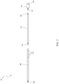
FIG. 7 is a front view of the lower support brace 50 as used with the system 10, according to the preferred embodiment of the present invention; and,
FIG. 8 is a front view of the support plate brace 180 as used with the system 10, according to the preferred embodiment of the present invention.
DESCRIPTIVE KEY
    • 10 extension ladder work platform standoff system
    • 15 extension ladder
    • 20 tray
    • 25 support structure
    • 30 non-slip pad
    • 35 vertical elevated surface
    • 40 user
    • 45 upper support arm
    • 50 lower support brace
    • 55 upper rung
    • 60 lower rung
    • 65 “U” shaped connector
    • 70 spring clip
    • 75 travel path
    • 80 central opening
    • 85 multiple slot opening
    • 90 raised outer rim
    • 95 lower extension of the central opening
    • 100 mounting plate
    • 105 fastener
    • 110 pad block
    • 115 mounting slot
    • 120 side opening
    • 125 first pin opening
    • 130 first half upper support arm
    • 135 first connector
    • 140 second half upper support arm
    • 145 second connector
    • 150 connecting tab
    • 155 first half lower support brace
    • 160 third connector
    • 165 second half lower support brace
    • 170 adjustable length connector
    • 175 length adjustment opening
    • 180 support plate brace
    • 185 second pin opening
DETAILED DESCRIPTION OF THE PREFERRED EMBODIMENT
The best mode for carrying out the invention is presented in terms of its preferred embodiment, herein depicted within FIGS. 1 through 8. However, the invention is not limited to the described embodiment, and a person skilled in the art will appreciate that many other embodiments of the invention are possible without deviating from the basic concept of the invention and that any such work around will also fall under the scope of this invention. It is envisioned that other styles and configurations of the present invention can be easily incorporated into the teachings of the present invention, and only one (1) particular configuration shall be shown and described for purposes of clarity and disclosure and not by way of limitation of scope.
The terms “a” and “an” herein do not denote a limitation of quantity, but rather denote the presence of at least one (1) of the referenced items.
Referring now to FIG. 1, a pictorial view of the extension ladder work platform standoff system 10, according to the preferred embodiment of the present invention is disclosed. The extension ladder work platform standoff system 10 (herein described as the “device”) 10, attaches to a standard extension ladder 15. The system 10 includes three (3) main components: a tray 20; a support structure 25; and a non-slip pad 30. The tray 20 can be used to hold paint cans, paint trays, tools, supplies and the like. The support structure 25 includes multiple supporting members that serve as a brace to hold both the tray 20 and the non-slip pad 30, but also serve to support the extension ladder 15 away from a vertical elevated surface 35 such as a wall, house, gutter or the like. The support provides access to items such as gutters, soffit or fascia without damaging said items as the support structure 25 allows bearing of the weight of the extension ladder 15 and a user 40 against other more suitable and durable surfaces. The non-slip pad 30 supports all bearing weight and provides two important benefits. First, the pad nature of the non-slip pad 30 provides cushioning for any protruding objects on the face of the vertical elevated surface 35 thus preventing damage such as scuffing. Second, the non-slip nature of the non-slip pad 30 ensures that the extension ladder 15 will not slip and fall should the user 40 go slightly off-center axis. Further description of the tray 20, the support structure 25, and the non-slip pad 30 will be provided herein below.
Referring next to FIGS. 2 and 3, a top side perspective view of the system 10, and a bottom side perspective view of the system 10, according to the preferred embodiment of the present invention is depicted. This figure provides clearer definition on the interconnecting nature of the components of the system 10. The support structure 25 includes two (2) upper support arms 45 (of which only one (1) is shown due to illustrative limitations) and two (2) lower support braces 50 (of which only one (1) is shown due to illustrative limitations). The upper support arms 45 is connected at the distal end to the non-slip pad 30 and at the proximal end to an upper rung 55 on the extension ladder 15. The lower support brace 50 is connected at the distal end to the non-slip pad 30 and at the proximal end to a lower rung 60 on the extension ladder 15. The lower rung 60 is envisioned to be two (2) rungs below the upper rung 55 for extension ladder 15 placed at a normal access angle.
The connection of the upper support arms 45 and the lower support brace 50 to the upper rung 55 and the lower rung 60 respectively are facilitated by four (4) “U”-shaped connectors 65 (of which only two (2) are shown due to illustrative limitations). Further description of the “U”-shaped connector 65 will be provided herein below. The tray 20 is connected horizontally across the two (2) upper support arms 45 (of which only one (1) is shown due to illustrative limitations) by use of four (4) spring clips 70 (of which only two (2) is shown due to illustrative limitations). Installation of the tray 20 is accomplished by pushing the tray 20 along a travel path 75 whereupon the tray 20 is held in place by friction fit.
Referring now to FIG. 4a , a front view of the tray 20 as used with the system 10, according to the preferred embodiment of the present invention is shown. The tray 20 is envisioned to be manufactured from a composite material, although other materials such as plastic, steel, aluminum, and the like can be used with equal effectiveness, and as such, the use of any specific material of construction should not be interpreted as a limiting factor of the present invention. The tray 20 is approximately eighteen inches (18 in.) deep and twenty-four inches (24 in.) wide. The tray 20 is provided with a central opening 80 for use in holding paint cans, tool buckets, or other circular objects (note that the central opening 80 is closed on the bottom), a series of multiple slot openings 85 for holding tools such as screwdrivers, pliers, hammers, utility knives, or the like, and a raised outer rim 90, to prevent tools or material from falling off.
Referring next to FIG. 4b , a side view of the tray 20 as used with the system 10, according to the preferred embodiment of the present invention is disclosed. This figure depicts a lower extension of the central opening 95 to allow for secure placement of any round objects within the central opening 80 (as shown in FIG. 4a ). Additionally, the spring clips 70 (two (2) of four (4) total shown) are depicted in a manner which exposed their spring nature and ability to hold the upper support arms 45 (as shown in FIG. 3).
Referring now to FIG. 5a , a rear view of the non-slip pad 30 as used with the system 10, according to the preferred embodiment of the present invention is depicted. The non-slip pad 30 is provided with a mounting plate 100, envisioned to be made of steel or other material of suitable strength. The mounting plate 100 is provided with three (3) fasteners 105 such as screws or rivets for holding the pad block 110 around the perimeter and on the opposite side. Additionally, the mounting plate 100 is provided with four (4) mounting slots 115 for holding the distal end of the two (2) upper support arms 45 (as shown in FIG. 2) and the two (2) lower support braces 50 (as shown in FIGS. 2 and 3). The mounting slots 115 are provided with side openings 120 for acceptance of a fastener such as screw, bolt, or pin (not shown). In at least one (1) embodiment, a pair of mounting slots 115 located on the inside of the mounting plate 100 are configured to secure the two (2) upper support arms 45 and a pair of mounting slots 115 located on the outside of the mounting plate 100 are configured to secure the two (2) lower support braces 50.
Referring next to FIG. 5b , a side view of the non-slip pad 30 as used with the system 10, according to the preferred embodiment of the present invention is shown. This figure provides disclosure of aforementioned side openings 120 located in the mounting slots 115 on the mounting plate 100. The pad block 110 is envisioned to be made of rubber, closed cell polyethylene foam, polyurethane foam, latex foam or the like. The pad block 110 would be approximately two inches (2 in.) deep and three inches (3 in.) high. The length of the pad block 110 would vary on the width of the extension ladder 15 (as shown in FIG. 1) upon which the system 10 is used, but would be approximately thirty inches (30 in.) long in a typical application.
Referring now to FIG. 6, a front view of the upper support arms 45 as used with the system 10, according to the preferred embodiment of the present invention is disclosed. The assembly of the upper support arms 45 includes three (3) major components. The “U”-shaped connector 65 (one (1) of four (4)) is located at one (1) end and is provided with a first pin opening 125 for securement by a pin, cotter pin, or similar device. It is connected to a first half upper support arm 130 by a first connector 135 such as a pinned connection, a threaded connection, a snap connection or the like. Likewise, the first half upper support arm 130 is connected to a second half upper support arm 140 by use of a second connector 145. The far end of the second half upper support arm 140 is provide with a connecting tab 150 which connects to the mounting slots 115 (as shown on FIG. 5a ) of the mounting plate 100 (as shown in FIG. 5b ).
Referring next to FIG. 7, a front view of the lower support brace 50 as used with the system 10, according to the preferred embodiment of the present invention is depicted. The assembly of the lower support brace 50 includes three (3) major components. The “U”-shaped connector 65 (one (1) of four (4)) is located at one (1) end and is provided with the first pin opening 125 for securement by a pin, cotter pin, or similar device. It is connected to a first half lower support brace 155 by a third connector 160 such as a pinned connection, a threaded connection, a snap connection or the like. The first half lower support brace 155 is then connected to a second half lower support brace 165 by use of an adjustable length connector 170. The adjustable length connector 170 allows for adjustment of the overall length of the lower support brace 50 to ensure that the tray 20 (as shown in FIG. 1) remain level. This adjustment would be required by environmental differences such as angle of the extension ladder 15 (as shown in FIG. 1), user preferences, and the like. Length adjustment is accomplished by a series of length adjustment openings 175 using a spring pin (not shown). The far end of the second half upper support arm 140 is provide with another connecting tab 150 which connects to the mounting slots 115 (as shown on FIG. 5a ) of the mounting plate 100 (as shown in FIG. 5b ).
Referring finally to FIG. 8, a front view of the support plate brace 180 as used with the system 10, according to the preferred embodiment of the present invention is depicted. The support plate brace 180 is envisioned to be manufactured from a steel plate with the approximate dimensions of three-quarters of an inch (¾ in.) wide, one-eighth of an inch (′/8 in.) thick and fifteen to eighteen inches (15-18 in.) wide. It is provided with two (2) second pin openings 185 at each end. Each second pin opening 185 is intended to line up with a first pin opening 125 (as shown in FIGS. 6 and 7) of the four (4) “U”-shaped connector 65 (as shown in FIGS. 6 and 7) on both the upper support arms 45 (as shown in FIGS. 6 and 7) and lower support brace 50 (as shown in FIGS. 6 and 7) near the end of the extension ladder 15. Such placement prevents the upper support arms 45 (as shown in FIGS. 6 and 7) and lower support brace 50 (as shown in FIGS. 6 and 7) from moving inward and preventing subsequent collapse of the system 10.
The preferred embodiment of the present invention can be utilized by the common user in a simple and effortless manner with little or no training. It is envisioned that the system 10 would be constructed in general accordance with FIG. 1 through FIG. 8.
After procurement of the system 10 it would be utilized in the following manner. First, attach the upper support arms 45 to the upper rung 55 using two (2) of the “U”-shaped connector 65 along with a pin and the support plate brace 180; attach the lower support brace 50 to the lower rung 60 using the other two (2) of the “U”-shaped connector 65 along with a pin and the other support plate brace 180; adjust the length of the lower support brace 50 using the adjustable length connector 170; attach the opposite end of both upper support arms 45 and both lower support brace 50 to the mounting plate 100 using fasteners 105; snap the tray 20 onto both upper support arms 45 using the spring clips 70 along a travel path 75. Finally, ensure that the extension ladder 15 is on stable grade. At this point in time the system 10 is ready to be utilized.
During utilization, various tools and supplies are placed upon the tray 20 to allow for more efficient and safer work at elevated heights. Any variations in center of gravity of the user 40 are more readily accommodated, the large surface area of the non-slip pad 30 prevents damage to the vertical elevated surface 35 and prevents slippage. After use, the abovementioned process is reversed to remove the system 10 whereupon it is stored for reuse at a future time in a cyclical manner.
The foregoing descriptions of specific embodiments of the present invention have been presented for purposes of illustration and description. They are not intended to be exhaustive or to limit the invention to the precise forms disclosed, and obviously many modifications and variations are possible in light of the above teaching. The embodiments were chosen and described in order to best explain the principles of the invention and its practical application, to thereby enable others skilled in the art to best utilize the invention and various embodiments with various modifications as are suited to the particular use contemplated.

Claims (8)

The invention claimed is:
1. A ladder platform device, comprising:
a tray;
a non-slip pad; and,
a plurality of lengthwise support structures;
wherein lengthwise support structures are removably secured to an underside portion of said tray;
wherein a first end of each said lengthwise support structures are removably secured to a first side of said non-slip pad, a first support structure includes a first upper support arm and a first lower support arm;
wherein a second end of a first pair of each said lengthwise support structures are removably secured to a first ladder rung;
wherein a second end of a second pair of each said lengthwise support structures are removably secured to a second ladder rung, a second support structure includes a second upper support arm and a second lower support arm; and,
wherein the first upper support arm, the second upper support arm, the first lower support arm and the second lower support arm are directly attached to said first side of said non-slip pad at a common horizontal line of attachment
wherein said non-slip pad is leaned against a vertical support structure thereby presenting said tray in a horizontal manner suitable for a usable surface for a user of a ladder;
wherein said non-slip comprises:
a first pad fastener secured to said first side of said non-slip pad;
a second pad fastener secured to said first side of said non-slip pad, adjacent said first pad fastener;
a third pad fastener secured to said first side of said non-slip pad, adjacent said second pad fastener; and,
a fourth pad fastener secured to said first side of said non-slip pad, adjacent said third pad fastener;
wherein said non-slip pad further comprises a pad block disposed on a second side of said non-slip pad, opposite said non-slip pad first side;
wherein said underside portion of said tray further comprises:
a first spring clip adjacent a first tray corner;
a second spring clip adjacent a second tray corner;
a third spring clip adjacent a third tray corner; and,
a fourth spring clip adjacent a fourth tray corner;
wherein said first upper support arm comprises:
a first upper support arm connector, having a first upper support arm connector first side and a first upper support arm connector second side;
a first upper support arm first half, having a first upper support arm first half first end removably secured to said first upper support arm connector second side, and also having a first upper support arm first half second end;
a first upper support arm second half, having a first upper support arm second half first end removably secured to said first upper support arm first half second end, and also having a first upper support arm second half second end; and,
a first upper support arm connection tab secured to said first upper support arm second half second end;
wherein said first upper support arm connector is secured to said first ladder rung;
wherein said first upper support arm is removably secured between said first spring clip and said second spring clip;
wherein said tray further comprises a plurality of apertures and at least one depression.
2. The device of claim 1, wherein said second upper support arm comprises:
a second upper support arm connector, having a second upper support arm connector first side and a second upper support arm connector second side;
a second upper support arm first half, having a second upper support arm first half first end removably secured to said second upper support arm connector second side, and also having a second upper support arm first half second end;
a second upper support arm second half, having a second upper support arm second half first end removably secured to said second upper support arm first half second end, and also having a second upper support arm second half second end; and,
a second upper support arm connection tab secured to said second upper support arm second half second end;
wherein said second upper support arm connector is removably secured to said first ladder rung adjacent said first upper support arm connector;
wherein said second upper support arm is removably secured between said third spring clip and said fourth spring clip;
wherein said second upper support arm connection tab is removably secured to said third pad fastener; and,
wherein a first support brace is secured at a first support brace end between said first upper support arm connector and said second upper support arm connector.
3. The device of claim 2, wherein said first lower support arm comprises:
a first lower support arm connector, having a first lower support arm connector first side and a first lower support arm connector second side;
a first lower support arm first half, having a first lower support arm first half first end removably secured to said first lower support arm connector second side, and also having a first lower support arm first half second end;
a first lower support arm second half, having a first lower support arm second half first end removably secured to said first lower support arm first half second end, and also having a first lower support arm second half second end; and,
a first lower support arm connection tab secured to said first lower support arm second half second end;
wherein said first lower support arm connector is removably secured to said second ladder rung subjacent said first ladder rung; and,
wherein said first lower support arm connection tab is removably secured to said first pad fastener.
4. The device of claim 3, wherein said second lower support arm comprises:
a second lower support arm connector, having a second lower support arm connector first side and a second lower support arm connector second side;
a second lower support arm first half, having a second lower support arm first half first end removably secured to said second lower support arm connector second side, and also having a second lower support arm first half second end;
a second lower support arm second half, having a second lower support arm second half first end removably secured to said second lower support arm first half second end, and also having a second lower support arm second half second end; and,
a second lower support arm connection tab secured to said second lower support arm second half second end;
wherein said second lower support arm connector is removably secured to said second ladder rung adjacent said first lower support arm connector;
wherein said second lower support arm connection tab is removably secured to said fourth pad fastener; and,
wherein a second support brace is secured at each second support brace end between said first lower support arm connector and said second lower support arm connector.
5. A ladder platform device, comprising:
a tray;
a non-slip pad; and,
a plurality of lengthwise adjustable support structures;
wherein at least two of said lengthwise adjustable support structures are removably secured to an underside portion of said tray;
wherein a first end of each said lengthwise adjustable support structures are removably secured to a first side of said non-slip pad, a first support structure includes a first upper support arm and a first lower support arm;
wherein a second end of a first pair of each said lengthwise adjustable support structures are removably secured to a first ladder rung;
wherein a second end of a second pair of each said lengthwise adjustable support structures are removably secured to a second ladder rung, a second support structure includes a second upper support arm and a second lower support arm; and,
wherein the first upper support arm, the second upper support arm, the first lower support arm and the second lower support arm are directly attached to said first side of said non-slip pad at a common horizontal line of attachment
wherein said non-slip pad is leaned against a vertical support structure thereby presenting said tray in a horizontal manner suitable for a usable surface for a user of a ladder;
wherein said non-slip comprises:
a first pad fastener secured to said first side of said non-slip pad;
a second pad fastener secured to said first side of said non-slip pad, adjacent said first pad fastener;
a third pad fastener secured to said first side of said non-slip pad, adjacent said second pad fastener; and,
a fourth pad fastener secured to said first side of said non-slip pad, adjacent said third pad fastener;
wherein said non-slip pad further comprises a pad block disposed on a second side of said non-slip pad, opposite said non-slip pad first side;
wherein said underside portion of said tray further comprises:
a first spring clip adjacent a first tray corner;
a second spring clip adjacent a second tray corner;
a third spring clip adjacent a third tray corner; and,
a fourth spring clip adjacent a fourth tray corner;
wherein said first upper support arm comprises:
a first upper support arm connector, having a first upper support arm connector first side and a first upper support arm connector second side;
a first upper support arm first half, having a first upper support arm first half first end removably secured to said first upper support arm connector second side, and also having a first upper support arm first half second end;
a first upper support arm second half, having a first upper support arm second half first end removably secured to said first upper support arm first half second end, and also having a first upper support arm second half second end; and,
a first upper support arm connection tab secured to said first upper support arm second half second end;
wherein said first upper support arm connector is secured to said first ladder rung;
wherein said first upper support arm is removably secured between said first spring clip and said second spring clip; and,
wherein said underside portion of said tray further comprises:
a first spring clip adjacent a first tray corner;
a second spring clip adjacent a second tray corner;
a third spring clip adjacent a third tray corner; and,
a fourth spring clip adjacent a fourth tray corner;
wherein said first upper support arm comprises:
a first upper support arm connector, having a first upper support arm connector first side and a first upper support arm connector second side;
a first upper support arm first half, having a first upper support arm first half first end removably secured to said first upper support arm connector second side, and also having a first upper support arm first half second end;
a first upper support arm second half, having a first upper support arm second half first end removably secured to said first upper support arm first half second end, and also having a first upper support arm second half second end; and,
a first upper support arm connection tab secured to said first upper support arm second half second end;
wherein said first upper support arm connector is secured to said first ladder rung;
wherein said first upper support arm is removably secured between said first spring clip and said second spring clip;
wherein said tray further comprises a plurality of apertures and at least one depression.
6. The device of claim 5, wherein said second upper support arm comprises:
a second upper support arm connector, having a second upper support arm connector first side and a second upper support arm connector second side;
a second upper support arm first half, having a second upper support arm first half first end removably secured to said second upper support arm connector second side, and also having a second upper support arm first half second end;
a second upper support arm second half, having a second upper support arm second half first end removably secured to said second upper support arm first half second end, and also having a second upper support arm second half second end; and,
a second upper support arm connection tab secured to said second upper support arm second half second end;
wherein said second upper support arm connector is removably secured to said first ladder rung adjacent said first upper support arm connector;
wherein said second upper support arm is removably secured between said third spring clip and said fourth spring clip;
wherein said second upper support arm connection tab is removably secured to said third pad fastener; and,
wherein a first support brace is secured at a first support brace end between said first upper support arm connector and said second upper support arm connector.
7. The device of claim 6, wherein said first lower support arm comprises:
a first lower support arm connector, having a first lower support arm connector first side and a first lower support arm connector second side;
a first lower support arm first half, having a first lower support arm first half first end removably secured to said first lower support arm connector second side, and also having a first lower support arm first half second end;
a first lower support arm second half, having a first lower support arm second half first end removably secured to said first lower support arm first half second end, and also having a first lower support arm second half second end; and,
a first lower support arm connection tab secured to said first lower support arm second half second end;
wherein said first lower support arm connector is removably secured to said second ladder rung subjacent said first ladder rung; and,
wherein said first lower support arm connection tab is removably secured to said first pad fastener.
8. The device of claim 7, wherein said second lower support arm comprises:
a second lower support arm connector, having a second lower support arm connector first side and a second lower support arm connector second side;
a second lower support arm first half, having a second lower support arm first half first end removably secured to said second lower support arm connector second side, and also having a second lower support arm first half second end;
a second lower support arm second half, having a second lower support arm second half first end removably secured to said second lower support arm first half second end, and also having a second lower support arm second half second end; and,
a second lower support arm connection tab secured to said second lower support arm second half second end;
wherein said second lower support arm connector is removably secured to said second ladder rung adjacent said first lower support arm connector;
wherein said second lower support arm connection tab is removably secured to said fourth pad fastener; and,
wherein a second support brace is secured at each second support brace end between said first lower support arm connector and said second lower support arm connector.
US15/792,897 2017-10-25 2017-10-25 Attachment for an extension ladder Expired - Fee Related US10619416B1 (en)

Priority Applications (1)

Application Number Priority Date Filing Date Title
US15/792,897 US10619416B1 (en) 2017-10-25 2017-10-25 Attachment for an extension ladder

Applications Claiming Priority (1)

Application Number Priority Date Filing Date Title
US15/792,897 US10619416B1 (en) 2017-10-25 2017-10-25 Attachment for an extension ladder

Publications (1)

Publication Number Publication Date
US10619416B1 true US10619416B1 (en) 2020-04-14

Family

ID=70223635

Family Applications (1)

Application Number Title Priority Date Filing Date
US15/792,897 Expired - Fee Related US10619416B1 (en) 2017-10-25 2017-10-25 Attachment for an extension ladder

Country Status (1)

Country Link
US (1) US10619416B1 (en)

Cited By (12)

* Cited by examiner, † Cited by third party
Publication number Priority date Publication date Assignee Title
US20210123302A1 (en) * 2019-10-24 2021-04-29 Core Distribution, Inc. Ladder tripod assembly and system
US20210246725A1 (en) * 2020-02-12 2021-08-12 Tricam Industries, Inc. Stepladder tray
US11525305B2 (en) * 2017-08-16 2022-12-13 Robert Loucks Ladder safety stabilizer
US20230023715A1 (en) * 2021-07-13 2023-01-26 Stephen D. ANDREWS Ladder stabilizer
US20230070052A1 (en) * 2021-09-03 2023-03-09 Tony Stone Safety attachment for ladders
US11828107B1 (en) * 2020-01-07 2023-11-28 Robert P. Warunek Ladder platform system
USD1009304S1 (en) 2022-02-07 2023-12-26 Tricam Industries, Inc. Three-step heavy-duty stepladder
USD1009303S1 (en) 2022-02-07 2023-12-26 Tricam Industries, Inc. Two-step heavy-duty stepladder
US20240328254A1 (en) * 2023-03-31 2024-10-03 iGas Inc Ladder with improved safety structures
US12331592B2 (en) 2020-12-22 2025-06-17 Tricam Industries, Llc Deep ladder tray
US12448771B2 (en) * 2022-04-20 2025-10-21 Ddp Specialty Electronic Materials Us, Llc Foam envelope for sealing large volumes
US12553284B2 (en) * 2024-02-06 2026-02-17 Philip F. Lanzafame Removable support platform for ladder

Citations (31)

* Cited by examiner, † Cited by third party
Publication number Priority date Publication date Assignee Title
US799782A (en) * 1904-09-06 1905-09-19 John G Ellinger Ladder-support.
US1004284A (en) * 1911-02-21 1911-09-26 Ferdinand Lehmann Adjustable ladder-support.
US1216214A (en) 1916-05-23 1917-02-13 Walter James Connell Step-ladder attachment.
US2541343A (en) * 1948-02-07 1951-02-13 Leonard F Dakin Supporting means for ladders and scaffolds
US2680554A (en) * 1949-10-15 1954-06-08 Leonard F Dakin Supporting means for ladders and scaffolds
US3179205A (en) * 1962-01-08 1965-04-20 Claude L Rowlette Ladder bracket
US3734236A (en) * 1971-12-16 1973-05-22 G Houtler Adjustable ladder platform
US4331217A (en) * 1980-04-16 1982-05-25 R.L.S. Enterprises, Inc. Ladder step and stabilizer
US4445659A (en) * 1978-05-30 1984-05-01 Paul Lachance Combination bracket and adjustable ladder tray
US4723632A (en) * 1986-09-12 1988-02-09 Gedgoudas Leo C E Extension ladder roof support attachment
US4862994A (en) * 1988-06-22 1989-09-05 Hughes Sr Earl E Ladder platform
USD307187S (en) 1988-09-02 1990-04-10 Bernard Schaf Work platform for extension ladders
US5052581A (en) * 1990-08-13 1991-10-01 Craft Creations Co., Inc. Ladder-supported holding tray
US5165501A (en) * 1991-07-25 1992-11-24 Donahey Howard E Ladder support attachment
US5361868A (en) * 1993-12-10 1994-11-08 Bartos Agnes M Step ladder boot kit
US5647452A (en) * 1995-09-15 1997-07-15 Gauthier; Gilbert E. Scafford jig
USD388883S (en) 1994-08-26 1998-01-06 Thivierge Gary R Ladder platform
US5899296A (en) * 1997-03-21 1999-05-04 Lantz; Harvey D. Step ladder scaffold apparatus
US6691825B2 (en) * 2002-04-24 2004-02-17 Voy Haig Adjustable ladder stabilizer and tool holder
US6698547B1 (en) * 2002-07-05 2004-03-02 Loren G. Uridel Ladder standoff
US6698548B1 (en) 2002-01-29 2004-03-02 Ernest C. Verrill Ladder platform
US20040200667A1 (en) * 2003-04-11 2004-10-14 Babkes Mitchell H. Hinge system for combination hand truck, step ladder and dolly device
US20070181761A1 (en) * 2006-02-03 2007-08-09 Werner Co. Work platform for a ladder and method
US20100200331A1 (en) * 2009-02-07 2010-08-12 Gregory Quinten Hager Toolshelf for extension ladder
USD683054S1 (en) * 2012-07-18 2013-05-21 Jacob's Ladder & Trailer, Inc. Ladder platform
US8469148B2 (en) * 2010-02-22 2013-06-25 Calvidge C. Perry Ladder tray
US20130220951A1 (en) * 2012-02-17 2013-08-29 Donald DUFOUR Shelf apparatus for use with a ladder and scaffold
US8881917B1 (en) * 2012-06-28 2014-11-11 Vajai Sooknanan Scaffold tool rest
US9771756B1 (en) * 2015-04-03 2017-09-26 Matthew Gregoire Ladder footing apparatus
US20170305602A1 (en) * 2016-04-24 2017-10-26 Franklin Steve Mittag Systems and Methods for Attaching a Container
US20180327002A1 (en) * 2017-05-11 2018-11-15 National Steel Car Limited Railroad freight car access fittings

Patent Citations (31)

* Cited by examiner, † Cited by third party
Publication number Priority date Publication date Assignee Title
US799782A (en) * 1904-09-06 1905-09-19 John G Ellinger Ladder-support.
US1004284A (en) * 1911-02-21 1911-09-26 Ferdinand Lehmann Adjustable ladder-support.
US1216214A (en) 1916-05-23 1917-02-13 Walter James Connell Step-ladder attachment.
US2541343A (en) * 1948-02-07 1951-02-13 Leonard F Dakin Supporting means for ladders and scaffolds
US2680554A (en) * 1949-10-15 1954-06-08 Leonard F Dakin Supporting means for ladders and scaffolds
US3179205A (en) * 1962-01-08 1965-04-20 Claude L Rowlette Ladder bracket
US3734236A (en) * 1971-12-16 1973-05-22 G Houtler Adjustable ladder platform
US4445659A (en) * 1978-05-30 1984-05-01 Paul Lachance Combination bracket and adjustable ladder tray
US4331217A (en) * 1980-04-16 1982-05-25 R.L.S. Enterprises, Inc. Ladder step and stabilizer
US4723632A (en) * 1986-09-12 1988-02-09 Gedgoudas Leo C E Extension ladder roof support attachment
US4862994A (en) * 1988-06-22 1989-09-05 Hughes Sr Earl E Ladder platform
USD307187S (en) 1988-09-02 1990-04-10 Bernard Schaf Work platform for extension ladders
US5052581A (en) * 1990-08-13 1991-10-01 Craft Creations Co., Inc. Ladder-supported holding tray
US5165501A (en) * 1991-07-25 1992-11-24 Donahey Howard E Ladder support attachment
US5361868A (en) * 1993-12-10 1994-11-08 Bartos Agnes M Step ladder boot kit
USD388883S (en) 1994-08-26 1998-01-06 Thivierge Gary R Ladder platform
US5647452A (en) * 1995-09-15 1997-07-15 Gauthier; Gilbert E. Scafford jig
US5899296A (en) * 1997-03-21 1999-05-04 Lantz; Harvey D. Step ladder scaffold apparatus
US6698548B1 (en) 2002-01-29 2004-03-02 Ernest C. Verrill Ladder platform
US6691825B2 (en) * 2002-04-24 2004-02-17 Voy Haig Adjustable ladder stabilizer and tool holder
US6698547B1 (en) * 2002-07-05 2004-03-02 Loren G. Uridel Ladder standoff
US20040200667A1 (en) * 2003-04-11 2004-10-14 Babkes Mitchell H. Hinge system for combination hand truck, step ladder and dolly device
US20070181761A1 (en) * 2006-02-03 2007-08-09 Werner Co. Work platform for a ladder and method
US20100200331A1 (en) * 2009-02-07 2010-08-12 Gregory Quinten Hager Toolshelf for extension ladder
US8469148B2 (en) * 2010-02-22 2013-06-25 Calvidge C. Perry Ladder tray
US20130220951A1 (en) * 2012-02-17 2013-08-29 Donald DUFOUR Shelf apparatus for use with a ladder and scaffold
US8881917B1 (en) * 2012-06-28 2014-11-11 Vajai Sooknanan Scaffold tool rest
USD683054S1 (en) * 2012-07-18 2013-05-21 Jacob's Ladder & Trailer, Inc. Ladder platform
US9771756B1 (en) * 2015-04-03 2017-09-26 Matthew Gregoire Ladder footing apparatus
US20170305602A1 (en) * 2016-04-24 2017-10-26 Franklin Steve Mittag Systems and Methods for Attaching a Container
US20180327002A1 (en) * 2017-05-11 2018-11-15 National Steel Car Limited Railroad freight car access fittings

Cited By (17)

* Cited by examiner, † Cited by third party
Publication number Priority date Publication date Assignee Title
US11525305B2 (en) * 2017-08-16 2022-12-13 Robert Loucks Ladder safety stabilizer
US20210123302A1 (en) * 2019-10-24 2021-04-29 Core Distribution, Inc. Ladder tripod assembly and system
US11795760B2 (en) * 2019-10-24 2023-10-24 Core Distribution, Inc. Ladder tripod assembly and system
US11828107B1 (en) * 2020-01-07 2023-11-28 Robert P. Warunek Ladder platform system
US20210246725A1 (en) * 2020-02-12 2021-08-12 Tricam Industries, Inc. Stepladder tray
US12084917B2 (en) * 2020-02-12 2024-09-10 Tricam Industries, Inc. Stepladder tray
US12331592B2 (en) 2020-12-22 2025-06-17 Tricam Industries, Llc Deep ladder tray
US11851950B2 (en) * 2021-07-13 2023-12-26 Ladder Armor Llc Ladder stabilizer
US20230023715A1 (en) * 2021-07-13 2023-01-26 Stephen D. ANDREWS Ladder stabilizer
US20230070052A1 (en) * 2021-09-03 2023-03-09 Tony Stone Safety attachment for ladders
US12378822B2 (en) * 2021-09-03 2025-08-05 Tony Stone Safety attachment for ladders
USD1009303S1 (en) 2022-02-07 2023-12-26 Tricam Industries, Inc. Two-step heavy-duty stepladder
USD1009304S1 (en) 2022-02-07 2023-12-26 Tricam Industries, Inc. Three-step heavy-duty stepladder
US12448771B2 (en) * 2022-04-20 2025-10-21 Ddp Specialty Electronic Materials Us, Llc Foam envelope for sealing large volumes
US20240328254A1 (en) * 2023-03-31 2024-10-03 iGas Inc Ladder with improved safety structures
US12546164B2 (en) * 2023-03-31 2026-02-10 iGas Inc Ladder with improved safety structures
US12553284B2 (en) * 2024-02-06 2026-02-17 Philip F. Lanzafame Removable support platform for ladder

Similar Documents

Publication Publication Date Title
US10619416B1 (en) Attachment for an extension ladder
US7753170B1 (en) Ladder top for retaining a ladder against extrinsic surfaces
US8925685B2 (en) Shelf apparatus for use with a ladder and scaffold
US9890589B2 (en) Step adapter for rung ladders
US10767417B2 (en) Accessory tray for attachment to a folding step ladder
US10006248B2 (en) Step adapter for rung ladders
US5052581A (en) Ladder-supported holding tray
US8033362B1 (en) Paint tray caddy for extension ladders and method of use thereof
US10633918B2 (en) Ladder storage receptacle
US20200048962A1 (en) Configurable ladder system and method
US3051428A (en) Self-leveling holding device
US5123620A (en) Accessory container for ladder
US20170014989A1 (en) Scaffold tray and tool case
US6698548B1 (en) Ladder platform
US9574400B2 (en) Vehicle hitch ladder support device
US10745969B1 (en) Storage device for storing work-tools and hangable to and removable from a ladder
US6105911A (en) Ladder caddy apparatus
US20060163003A1 (en) Ladder-mountable toolbox
US20140083888A1 (en) Extension Ladder Tool Caddie
US10039379B1 (en) Material support and storage rack
US5558306A (en) Inclined surface support platform
US20060226310A1 (en) Method of supporting tools and supplies upon a sloped surface
US9518425B2 (en) Ladder caddy assembly
US20140224703A1 (en) Removable tray accessory for a-frame ladder
US20170198523A1 (en) Ladder accessories

Legal Events

Date Code Title Description
FEPP Fee payment procedure

Free format text: ENTITY STATUS SET TO UNDISCOUNTED (ORIGINAL EVENT CODE: BIG.); ENTITY STATUS OF PATENT OWNER: MICROENTITY

FEPP Fee payment procedure

Free format text: ENTITY STATUS SET TO MICRO (ORIGINAL EVENT CODE: MICR); ENTITY STATUS OF PATENT OWNER: MICROENTITY

FEPP Fee payment procedure

Free format text: ENTITY STATUS SET TO MICRO (ORIGINAL EVENT CODE: MICR); ENTITY STATUS OF PATENT OWNER: MICROENTITY

STCF Information on status: patent grant

Free format text: PATENTED CASE

FEPP Fee payment procedure

Free format text: MAINTENANCE FEE REMINDER MAILED (ORIGINAL EVENT CODE: REM.); ENTITY STATUS OF PATENT OWNER: MICROENTITY

LAPS Lapse for failure to pay maintenance fees

Free format text: PATENT EXPIRED FOR FAILURE TO PAY MAINTENANCE FEES (ORIGINAL EVENT CODE: EXP.); ENTITY STATUS OF PATENT OWNER: MICROENTITY

STCH Information on status: patent discontinuation

Free format text: PATENT EXPIRED DUE TO NONPAYMENT OF MAINTENANCE FEES UNDER 37 CFR 1.362

FP Lapsed due to failure to pay maintenance fee

Effective date: 20240414