US10615744B2 - Intelligent solar cell carrier system for flight and laboratory measurement applications - Google Patents
Intelligent solar cell carrier system for flight and laboratory measurement applications Download PDFInfo
- Publication number
- US10615744B2 US10615744B2 US15/675,772 US201715675772A US10615744B2 US 10615744 B2 US10615744 B2 US 10615744B2 US 201715675772 A US201715675772 A US 201715675772A US 10615744 B2 US10615744 B2 US 10615744B2
- Authority
- US
- United States
- Prior art keywords
- solar cell
- pcb
- measurement system
- temperature
- voltage
- Prior art date
- Legal status (The legal status is an assumption and is not a legal conclusion. Google has not performed a legal analysis and makes no representation as to the accuracy of the status listed.)
- Active, expires
Links
- 238000011545 laboratory measurement Methods 0.000 title 1
- 229910052751 metal Inorganic materials 0.000 claims abstract description 25
- 239000002184 metal Substances 0.000 claims abstract description 25
- 238000009529 body temperature measurement Methods 0.000 claims abstract description 14
- 238000004891 communication Methods 0.000 claims abstract description 9
- 239000000853 adhesive Substances 0.000 claims abstract description 8
- 230000001070 adhesive effect Effects 0.000 claims abstract description 8
- 239000000463 material Substances 0.000 claims abstract description 7
- 238000005259 measurement Methods 0.000 claims description 105
- 230000000903 blocking effect Effects 0.000 claims description 3
- 239000003973 paint Substances 0.000 claims description 3
- RYGMFSIKBFXOCR-UHFFFAOYSA-N Copper Chemical compound [Cu] RYGMFSIKBFXOCR-UHFFFAOYSA-N 0.000 description 10
- 230000008901 benefit Effects 0.000 description 10
- 239000010949 copper Substances 0.000 description 10
- 229910052802 copper Inorganic materials 0.000 description 10
- 229910052782 aluminium Inorganic materials 0.000 description 6
- XAGFODPZIPBFFR-UHFFFAOYSA-N aluminium Chemical compound [Al] XAGFODPZIPBFFR-UHFFFAOYSA-N 0.000 description 6
- 239000000758 substrate Substances 0.000 description 4
- 238000013461 design Methods 0.000 description 3
- 238000005516 engineering process Methods 0.000 description 3
- 230000010006 flight Effects 0.000 description 3
- 238000002955 isolation Methods 0.000 description 3
- 229910000679 solder Inorganic materials 0.000 description 3
- 238000006243 chemical reaction Methods 0.000 description 2
- 150000001875 compounds Chemical class 0.000 description 2
- 238000010276 construction Methods 0.000 description 2
- 230000006870 function Effects 0.000 description 2
- 229920001296 polysiloxane Polymers 0.000 description 2
- 238000004382 potting Methods 0.000 description 2
- 238000011160 research Methods 0.000 description 2
- 239000004593 Epoxy Substances 0.000 description 1
- XUIMIQQOPSSXEZ-UHFFFAOYSA-N Silicon Chemical compound [Si] XUIMIQQOPSSXEZ-UHFFFAOYSA-N 0.000 description 1
- 230000009286 beneficial effect Effects 0.000 description 1
- 238000012512 characterization method Methods 0.000 description 1
- 238000004590 computer program Methods 0.000 description 1
- 238000013500 data storage Methods 0.000 description 1
- 230000001419 dependent effect Effects 0.000 description 1
- 230000000694 effects Effects 0.000 description 1
- 230000005611 electricity Effects 0.000 description 1
- 125000003700 epoxy group Chemical group 0.000 description 1
- 238000002474 experimental method Methods 0.000 description 1
- 238000010438 heat treatment Methods 0.000 description 1
- 230000010354 integration Effects 0.000 description 1
- 239000011159 matrix material Substances 0.000 description 1
- 238000000034 method Methods 0.000 description 1
- 238000012986 modification Methods 0.000 description 1
- 230000004048 modification Effects 0.000 description 1
- 229920000647 polyepoxide Polymers 0.000 description 1
- 229910052710 silicon Inorganic materials 0.000 description 1
- 239000010703 silicon Substances 0.000 description 1
- 239000013464 silicone adhesive Substances 0.000 description 1
- 238000010408 sweeping Methods 0.000 description 1
- 238000012360 testing method Methods 0.000 description 1
Images


Classifications
-
- H—ELECTRICITY
- H02—GENERATION; CONVERSION OR DISTRIBUTION OF ELECTRIC POWER
- H02S—GENERATION OF ELECTRIC POWER BY CONVERSION OF INFRARED RADIATION, VISIBLE LIGHT OR ULTRAVIOLET LIGHT, e.g. USING PHOTOVOLTAIC [PV] MODULES
- H02S50/00—Monitoring or testing of PV systems, e.g. load balancing or fault identification
- H02S50/10—Testing of PV devices, e.g. of PV modules or single PV cells
-
- G—PHYSICS
- G01—MEASURING; TESTING
- G01K—MEASURING TEMPERATURE; MEASURING QUANTITY OF HEAT; THERMALLY-SENSITIVE ELEMENTS NOT OTHERWISE PROVIDED FOR
- G01K1/00—Details of thermometers not specially adapted for particular types of thermometer
- G01K1/14—Supports; Fastening devices; Arrangements for mounting thermometers in particular locations
-
- G—PHYSICS
- G01—MEASURING; TESTING
- G01K—MEASURING TEMPERATURE; MEASURING QUANTITY OF HEAT; THERMALLY-SENSITIVE ELEMENTS NOT OTHERWISE PROVIDED FOR
- G01K7/00—Measuring temperature based on the use of electric or magnetic elements directly sensitive to heat ; Power supply therefor, e.g. using thermoelectric elements
- G01K7/16—Measuring temperature based on the use of electric or magnetic elements directly sensitive to heat ; Power supply therefor, e.g. using thermoelectric elements using resistive elements
-
- Y—GENERAL TAGGING OF NEW TECHNOLOGICAL DEVELOPMENTS; GENERAL TAGGING OF CROSS-SECTIONAL TECHNOLOGIES SPANNING OVER SEVERAL SECTIONS OF THE IPC; TECHNICAL SUBJECTS COVERED BY FORMER USPC CROSS-REFERENCE ART COLLECTIONS [XRACs] AND DIGESTS
- Y02—TECHNOLOGIES OR APPLICATIONS FOR MITIGATION OR ADAPTATION AGAINST CLIMATE CHANGE
- Y02E—REDUCTION OF GREENHOUSE GAS [GHG] EMISSIONS, RELATED TO ENERGY GENERATION, TRANSMISSION OR DISTRIBUTION
- Y02E10/00—Energy generation through renewable energy sources
- Y02E10/50—Photovoltaic [PV] energy
Definitions
- the present invention relates to solar cell measurements, and more particularly, to a solar cell measurement system configured to measure properties of a solar cell.
- NSCAP Advanced Photovoltaics
- AFRL Air Force Research Laboratory
- NNL Naval Research Laboratory
- NAA National Aeronautics and Space Administration
- PCB printed circuit board
- the NSCAP holder is not without limitations. Integration of a solar cell sample into this holder is a non-trivial process that includes: (i) a space-qualified silicone adhesive used to mount the cell to the aluminum plate; (ii) electrical connections that are made to a separate PCB, which fits on top of the aluminum plate: (iii) an analog temperature sensor that is mounted in a thermally conductive potting compound to the backside of the aluminum plate and is also electrically connected to the PCB; and (iv) the solar cell and temperature leads are connected to a costly, custom electrical connector that interfaces with an external source measurement unit (SMU).
- SMU external source measurement unit
- a typical external SMU is a Keithley 2425, which is a bulky and heavy laboratory-grade instrument.
- the bulky footprint of this combined high altitude solar cell instrumentation package limits solar cell measurement opportunities to an expensive, high altitude balloon or aircraft programs such as government sanctioned balloon flights, NASA Learjet or ER-2 aircraft.
- NASA Learjet or ER-2 aircraft may fly on an approximate annual basis, only a small area is set aside for hosted experiments on these aircraft. Therefore, only a small number of samples can be flown per flight, further adding to the cost.
- a high-altitude balloon using the NSCAP package may fly more solar cell samples than the high-altitude aircraft, but the total weight does not decrease, again limiting the number of flights and driving up cost.
- a common cost estimate for flying a NSCAP balloon is approximately $1M to 2M.
- the Learjet and ER-2 fly approximately once a year, and oftentimes, only one of the aircraft will fly. The last ER-2 flight was May 2016 and the Learjet has not flown in almost two years.
- the NSCAP holder also presents technical limitations that remain to be quantified.
- a thermal gradient between the solar cell, silicon adhesive, aluminum plate, and potting compound of the temperature sensor presents a challenge on precise measurement of the solar cell temperature.
- the NSCAP partnership has not demonstrated whether the temperature sensor configuration enables accurate measurement of the solar cell temperature.
- the temperature sensor outputs an analog current that must be converted to a digital voltage value. The conversion of values from analog to digital differs for different external SMUs and introduces variable amounts of error.
- Certain embodiments of the present invention may provide solutions to the problems and needs in the art that have not yet been fully identified, appreciated, or solved by current solar cell measurement systems.
- certain embodiments of the present invention generally pertain to a solar cell measurement system that includes current-voltage measurement electronics and may be operated remotely by a device, such as a smart phone and a software application, by way of Bluetooth technology.
- an apparatus in an embodiment, includes a metal core PCB configured to provide temperature measurements of one or more solar cells.
- the metal core PCB includes a plurality of layers formed on top of a substrate.
- the plurality of layers includes at least two dielectric layers and at least two copper layers.
- the apparatus includes a temperature sensor and the one or more solar cells that are placed on top of one of the at least two copper layers, such that the temperature sensor and the one or more solar cells are electrically isolated from each other.
- an apparatus for carrying, retrieving, and characterizing temperature and current-voltage properties of a solar cell includes a metal core PCB comprising current-voltage and temperature electronics operated by a remote device via a communication unit.
- the apparatus also includes the solar cell, which is embedded onto the metal core PCB by way of a thermally- and electrically-conductive adhesive material.
- the current-voltage and temperature electronics and the solar cell are thermally connected to the PCB, while being electrically isolated from each other, but reside on the same plane of the PCB.
- a solar cell measurement system may include a metal core PCB embedded with integrated circuits and is remotely controlled by a remote device, allowing for temperature measurements and current-voltage measurements of a solar cell.
- the solar cell is embedded onto the metal core PCB by way of a thermally- and electrically-conductive adhesive material, and a temperature sensor embedded on the metal core PCB is electrically isolated from the solar cell while remaining on a same plane.
- FIG. 1 illustrates a measurement unit as a component of the solar cell measurement system, according to an embodiment of the present invention.
- FIG. 2 illustrates a solar cell measurement system, according to an embodiment of the present invention.
- FIG. 3 illustrates a solar cell measurement system with a BLE module, according to an embodiment of the present invention.
- FIG. 4 illustrates a solar cell measurement unit with a remote module, according to an embodiment of the present invention.
- FIG. 5 illustrates a daisy chained solar cell measurement system, according to an embodiment of the present invention.
- FIG. 6 illustrates a baffle that may limit stray light to all or part of a solar cell, according to an embodiment of the present invention.
- FIG. 7 illustrates a PCB stack for the solar cell measurement system, according to an embodiment of the present invention.
- Some embodiments generally pertain to an intelligent solar cell carrier (iSC 2 ) system for carrying, retrieving, and characterizing temperature and current-voltage properties of a solar cell.
- the iSC 2 system may be referred to as a solar cell measurement system for purposes of explanation and simplicity.
- the solar cell measurement system is a low cost measurement device, and in some embodiments, is approximately 2′′H ⁇ 3′′L ⁇ 0.0625′′ W.
- the solar cell measurement system may include a metal core PCB, integrated circuits (IC), and a computer program (or software) that enables accurate and precise temperature and current-voltage measurements of solar cells in any environment such as space, near space, or ground without the need for a full laboratory setup.
- the solar cell measurement system allows for measurement of solar cell properties without the need for an expensive source measurement unit and custom software.
- the solar cell measurement system may interface with a personal computer (PC), smart phones, or tablet via Bluetooth low energy (BLE) technology and an included software application.
- PC personal computer
- BLE Bluetooth low energy
- FIG. 1 illustrates a measurement unit 100 as a component of the solar cell measurement system, according to an embodiment of the present invention.
- measurement unit 100 is a System in Package (SIP) device, which include electronics that are necessary for all measurements (e.g., current-voltage and temperature measurements), heater control, remote communication, and data storage.
- SIP System in Package
- the modules listed below are meant to be used in conjunction with the measurement unit for various applications.
- Measurement unit 100 may include measurement and control electronics used by one or more modules within the solar cell measurement system.
- a microcontroller (or “ ⁇ Controller”) 102 may control IV sweep electronics 104 , temperature measurement electronics (or external temperature (RTD) measurement) 106 , heater control electronics (or heater) 108 , and an embedded memory (e.g., EEPROM) 110 for storing calibration data.
- ⁇ Controller or “ ⁇ Controller”
- EEPROM embedded memory
- Measurement unit 100 may include a bus 114 .
- measurement unit 100 may address selection pins for daisy chaining devices using the I 2 C bus, for example. This may allow for up to 128 devices on a bus.
- measurement unit 100 may use an UART communication bus.
- power regulation electronics 112 provide remote enable/disable, short circuit protection, and a single 5V-12V power rail.
- measurement unit 100 may perform current-voltage (I-V) measurements under light as well as in the dark.
- I-V current-voltage
- a forward biased source voltage is supplied from the main power rail of power source 112 .
- This forward biased source voltage can be enabled or disabled by measurement unit 100 depending on the type of measurement being made.
- a load is applied to the solar cell (not shown) by sweeping a MOSFET in the linear mode. This load is determined by a voltage set by measurement unit 100 , and gradually stepped through the range of values between short circuit current and open circuit voltage.
- An optimized algorithm may determine the step points depending on the cell characteristics.
- the measurement resolution in certain embodiments is partially determined by the minimum and maximum values of the measured solar cell.
- the analog digital converter (ADC) may be a 24-bit module that makes full 4-wire measurements of the device under test (DUT).
- Measurement unit 100 may include electronics, such as temperature measurement electronics 106 , necessary to perform a 4-wire measurement on a temperature sensor (not shown) requiring a current source. This can be an RTD, a diode sensor, or any sensor that varies its resistance with temperature. Measurement unit 100 may also include internal temperature sensors on both microcontroller 102 and the ADC to provide temperature compensated conversions. The accuracy of the temperature measurement is dependent on the sensor, and is capable of ⁇ 0.1° C. accuracy with a resolution of 0.001° C. in some embodiments.
- FIG. 2 illustrates a solar cell measurement system 200 , according to an embodiment of the present invention.
- solar cell measurement system 200 incorporates measurement unit 202 , along with a USB 204 interface for communicating with a remote host such as a computer, smart device, tablet, etc.
- Measurement unit 202 is made using metal core PCB technology.
- the metal core PCB has high thermal conductivity dielectric between the backplane and the top copper layer, and is painted with high reflectance white paint. See, for example, FIG. 7 , which discusses the metal core PCB and stack up of the layers of the metal core PCB in more detail.
- a temperature sensor 206 is mounted near solar cell 208 , providing very small thermal gradients between solar cell 208 and temperature sensor 206 .
- an embedded heater circuit 210 is built into the PCB below solar cell 208 , which can be controlled via solar cell measurement system 200 . Heater 210 may be resized to provide varying heating capability depending on the application.
- Connectors A and B are matching male (A) and female (B) connectors, allowing for daisy-chaining of modules together. Connectors A and B share the same power rails, enable, and communication pins. When connected, the modules may communicate with a host computer device using a single USB connection.
- FIG. 3 illustrates a solar cell measurement system 300 with a BLE module 304 , according to an embodiment of the present invention.
- solar cell measurement system 300 functions and operates similar to the solar cell measurement system 200 of FIG. 2 in terms of metal core PCB construction.
- BLE module 304 does not contain a USB connection. Instead, BLE module 304 is powered by a power source 306 , such as a coin cell battery in some embodiments, and communicates with a host device, such as a computer, tablet, cell phone, etc., using the BLE protocol.
- a power source 306 such as a coin cell battery in some embodiments
- a host device such as a computer, tablet, cell phone, etc.
- the features discussed above in FIG. 2 may also be incorporated in the solar cell measurement unit 300 , and may further include remote accessibility.
- a solar cell 308 is mounted on solar cell measurement system 300 , and may store data within measurement unit 302 and additionally on a BLE communication device via BLE module 304 .
- temperature sensor 310 of FIG. 3 and temperature sensor 206 of FIG. 2 are 4-wire measurements of a remote sensor (RTD in certain embodiments).
- FIG. 4 illustrates a solar cell measurement unit 400 with a remote module 406 , according to an embodiment of the present invention.
- remote module 406 may remove the measurement and control electronics found, as shown in FIG. 1 for example, to a remote location.
- remote module 406 may include solar cell 408 and temperature sensor 410 . Solar cell 408 and temperature sensor 410 may operate and/or function in a similar manner as discussed above in FIGS. 2 and 3 .
- measurement unit 402 may perform 4 wire measurements on remote module 406 via connectors 412 .
- connectors 412 may be a ribbon cable of any type containing at least 10 wires, 2 4-wire measurements, one for temperature sensor 410 and one for solar cell 408 , and two additional wires for heater control.
- 4-wire measurements cable length is not an issue in measurement accuracy.
- the heater (not shown) can still be controlled remotely as well.
- the benefit of the remote measurement embodiment, as shown in FIG. 4 is that a smaller footprint is needed facing the sun. In most uses, space is limited for mounting sun facing samples. By moving the measurement electronics 400 behind cell carrier 406 , more samples may be placed on the same footprint.
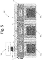
- FIG. 5 illustrates a daisy chained solar cell measurement system 500 , according to an embodiment of the present invention.
- FIG. 5 shows a system 500 composed of three solar cell measurement system 502 1 to 502 3 daisy chained together, a person of ordinary skill in the art would readily appreciate that any number of solar cell measurement systems may be daisy chained together.
- each solar cell measurement system 502 1-3 includes a connector A and connector B configured to connect one solar cell measurement system to another.
- connector 504 may be a universal serial bus (USB) 4-wire cable. This configuration is useful when simultaneous data is required. For example, this embodiment may be utilized when measuring the uniformity of a light source with a matrix of cells connected.
- FIG. 6 illustrates a baffle 600 that may limit stray light to all or part of a solar cell, according to an embodiment of the present invention.
- baffle 600 has been designed to be incorporated into the solar cell measurement systems shown in FIGS. 1-5 .
- baffle 600 may be attached to the solar cell measurement system, and placed directly, or partially, over solar cell 602 .
- Baffle 600 in some embodiments is secured using a tension fit or screws from the back of the PCB module.
- Baffle 600 may incorporate multiple light blocking structures 602 that limit the angle of incidence on solar cell 604 to 5 degrees. It should be appreciated that the angle of incidence may depend based on design choice. In other words, the angle of incidence is not limited to 5 degrees.
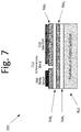
- FIG. 7 illustrates a PCB stack 700 for the solar cell measurement system, according to an embodiment of the present invention.
- PCB stack 700 utilizes a metal core PCB, providing accurate temperature measurements of the solar cells.
- the metal core PCB includes a plurality of layers formed on top of aluminum or copper substrate 702 .
- a first (thermally conductive/electrically insulating) dielectric layer 704 1 is placed on top of substrate 702 .
- Sandwiched between dielectric layers 704 1 , 704 2 is a copper layer 706 1 .
- Another copper layer 706 2 is placed on top of dielectric layer 704 2 .
- This configuration allows for electrical isolation of temperature sensor(s) 708 from solar cell 710 that is being measured.
- the thermally conductive dielectric allows low error temperature measurements of solar cell 710 using sensor 708 .
- temperature sensor 708 is placed on top of copper layer 7062 and is electrically isolated from solar cell 710 . This way, both a current-voltage sweep and temperature measurement can be performed. This configuration may be necessary because as a solar cell 710 is being measured, solar cell 710 produces power by converting sunlight to electricity. If solar cell 710 , which is producing power, is electrically connected to temperature sensor 708 , temperature sensor's 708 temperature measurement can be affected.
- an adhesive-less bond 712 is used to attach solar cell 710 to copper layer 706 2 .
- solar cell 710 may be mounted to metal core PCB 700 by solder or adhered via electrically- and thermally-conducting epoxies, silicones, or pastes (e.g., adhesive-less bond 712 ).
- thermo conductivity and electrical isolation of the temperature sensor and solar cell as shown in FIG. 7 enables accurate temperature measurements of the solar cell.
- a direct thermal path is made between the solar cell, the solder/thermal adhesive, Copper top layer, thermal dielectric, copper layer, solder, and temperature sensor.
- the most thermally-resistive material in the thermal path is the thermal dielectric at 4 W/m-K, for example. Further, all the other materials may have thermal conductivities near 100 W/m-K.
- Embodiments described herein may use an adhesive to mount the solar cell to a substrate with thermal conductivities near 0.2 W/K, making the solar cell measurement system 20 times more thermally-conductive and ultimately enabling a more accurate measurement of the solar cell's temperature.
Landscapes
- Physics & Mathematics (AREA)
- General Physics & Mathematics (AREA)
- Photometry And Measurement Of Optical Pulse Characteristics (AREA)
Abstract
Description
Claims (16)
Priority Applications (1)
| Application Number | Priority Date | Filing Date | Title |
|---|---|---|---|
| US15/675,772 US10615744B2 (en) | 2017-08-13 | 2017-08-13 | Intelligent solar cell carrier system for flight and laboratory measurement applications |
Applications Claiming Priority (1)
| Application Number | Priority Date | Filing Date | Title |
|---|---|---|---|
| US15/675,772 US10615744B2 (en) | 2017-08-13 | 2017-08-13 | Intelligent solar cell carrier system for flight and laboratory measurement applications |
Publications (2)
| Publication Number | Publication Date |
|---|---|
| US20190052225A1 US20190052225A1 (en) | 2019-02-14 |
| US10615744B2 true US10615744B2 (en) | 2020-04-07 |
Family
ID=65275724
Family Applications (1)
| Application Number | Title | Priority Date | Filing Date |
|---|---|---|---|
| US15/675,772 Active 2038-05-03 US10615744B2 (en) | 2017-08-13 | 2017-08-13 | Intelligent solar cell carrier system for flight and laboratory measurement applications |
Country Status (1)
| Country | Link |
|---|---|
| US (1) | US10615744B2 (en) |
Families Citing this family (1)
| Publication number | Priority date | Publication date | Assignee | Title |
|---|---|---|---|---|
| CN113489456A (en) * | 2021-05-21 | 2021-10-08 | 中国科学院空天信息创新研究院 | High-altitude calibration device for space solar cell |
Citations (18)
| Publication number | Priority date | Publication date | Assignee | Title |
|---|---|---|---|---|
| US5125983A (en) * | 1991-04-22 | 1992-06-30 | Electric Power Research Institute, Inc. | Generating electric power from solar radiation |
| US20080135095A1 (en) * | 2006-08-25 | 2008-06-12 | Coolearth Solar, Inc. | Rigging system for supporting and pointing solar concentrator arrays |
| US20090272427A1 (en) * | 2006-12-05 | 2009-11-05 | Andreas Bett | Photovoltaic module and the use thereof |
| US20100300509A1 (en) * | 2009-05-26 | 2010-12-02 | Douglas William Raymond | Solar photovoltaic modules with integral wireless telemetry |
| US20110088744A1 (en) * | 2009-10-21 | 2011-04-21 | Bp Corporation North America Inc. | Photovoltaic Module Failure Detection Devices and Methods |
| CN201887055U (en) * | 2010-11-11 | 2011-06-29 | 苏州快可光伏电子股份有限公司 | Photovoltaic junction box adopting wireless monitoring system |
| US20110316343A1 (en) * | 2010-06-25 | 2011-12-29 | International Business Machines Corporation | Photovoltaic module with integrated diagnostics |
| US20120006383A1 (en) * | 2008-11-20 | 2012-01-12 | Donnelly Sean M | Heat exchanger apparatus and methods of manufacturing cross reference |
| US20120312351A1 (en) * | 2008-10-02 | 2012-12-13 | Raydyne Energy, Inc. | Efficient solar energy concentrator with improved thermal management |
| US20130092216A1 (en) * | 2011-10-17 | 2013-04-18 | Array Power Inc. | Solar Cell Module Junction Box |
| CN202977270U (en) * | 2012-11-20 | 2013-06-05 | 厦门智能达电控有限公司 | Intelligent alternating-current high-voltage isolation switch |
| CN103294102A (en) * | 2012-11-02 | 2013-09-11 | 许昌学院电气信息工程学院 | Solar CVT control method based on temperature detection |
| CN105024623A (en) * | 2015-07-03 | 2015-11-04 | 广西鱼峰水泥股份有限公司 | Method for shortening fault time of sack-making machine |
| US20170115167A1 (en) * | 2015-10-27 | 2017-04-27 | Nuflare Technology, Inc. | Temperature measuring mask and temperature measuring method |
| US20170244358A1 (en) * | 2013-04-13 | 2017-08-24 | Solexel, Inc. | Solar photovoltaic module remote access module switch and real-time temperature monitoring |
| US20170373207A1 (en) * | 2016-06-28 | 2017-12-28 | Lg Electronics Inc. | Solar cell module, method for manufacturing solar cell module, method for manufacturing electronic device having solar cell module |
| US20180175789A1 (en) * | 2009-12-16 | 2018-06-21 | Nagendra Srinivas Cherukupalli | Systems, circuits and methods for monitoring and dynamically configuring solar cells |
| US20180323333A1 (en) * | 2014-05-27 | 2018-11-08 | Sunpower Corporation | Shingled solar cell module |
-
2017
- 2017-08-13 US US15/675,772 patent/US10615744B2/en active Active
Patent Citations (19)
| Publication number | Priority date | Publication date | Assignee | Title |
|---|---|---|---|---|
| US5125983A (en) * | 1991-04-22 | 1992-06-30 | Electric Power Research Institute, Inc. | Generating electric power from solar radiation |
| US20080135095A1 (en) * | 2006-08-25 | 2008-06-12 | Coolearth Solar, Inc. | Rigging system for supporting and pointing solar concentrator arrays |
| US20090272427A1 (en) * | 2006-12-05 | 2009-11-05 | Andreas Bett | Photovoltaic module and the use thereof |
| US7977567B2 (en) * | 2006-12-05 | 2011-07-12 | Fraunhofer-Gesellschaft Zur Forderung Angewandten Forschung E.V. | Photovoltaic module and the use thereof |
| US20120312351A1 (en) * | 2008-10-02 | 2012-12-13 | Raydyne Energy, Inc. | Efficient solar energy concentrator with improved thermal management |
| US20120006383A1 (en) * | 2008-11-20 | 2012-01-12 | Donnelly Sean M | Heat exchanger apparatus and methods of manufacturing cross reference |
| US20100300509A1 (en) * | 2009-05-26 | 2010-12-02 | Douglas William Raymond | Solar photovoltaic modules with integral wireless telemetry |
| US20110088744A1 (en) * | 2009-10-21 | 2011-04-21 | Bp Corporation North America Inc. | Photovoltaic Module Failure Detection Devices and Methods |
| US20180175789A1 (en) * | 2009-12-16 | 2018-06-21 | Nagendra Srinivas Cherukupalli | Systems, circuits and methods for monitoring and dynamically configuring solar cells |
| US20110316343A1 (en) * | 2010-06-25 | 2011-12-29 | International Business Machines Corporation | Photovoltaic module with integrated diagnostics |
| CN201887055U (en) * | 2010-11-11 | 2011-06-29 | 苏州快可光伏电子股份有限公司 | Photovoltaic junction box adopting wireless monitoring system |
| US20130092216A1 (en) * | 2011-10-17 | 2013-04-18 | Array Power Inc. | Solar Cell Module Junction Box |
| CN103294102A (en) * | 2012-11-02 | 2013-09-11 | 许昌学院电气信息工程学院 | Solar CVT control method based on temperature detection |
| CN202977270U (en) * | 2012-11-20 | 2013-06-05 | 厦门智能达电控有限公司 | Intelligent alternating-current high-voltage isolation switch |
| US20170244358A1 (en) * | 2013-04-13 | 2017-08-24 | Solexel, Inc. | Solar photovoltaic module remote access module switch and real-time temperature monitoring |
| US20180323333A1 (en) * | 2014-05-27 | 2018-11-08 | Sunpower Corporation | Shingled solar cell module |
| CN105024623A (en) * | 2015-07-03 | 2015-11-04 | 广西鱼峰水泥股份有限公司 | Method for shortening fault time of sack-making machine |
| US20170115167A1 (en) * | 2015-10-27 | 2017-04-27 | Nuflare Technology, Inc. | Temperature measuring mask and temperature measuring method |
| US20170373207A1 (en) * | 2016-06-28 | 2017-12-28 | Lg Electronics Inc. | Solar cell module, method for manufacturing solar cell module, method for manufacturing electronic device having solar cell module |
Also Published As
| Publication number | Publication date |
|---|---|
| US20190052225A1 (en) | 2019-02-14 |
Similar Documents
| Publication | Publication Date | Title |
|---|---|---|
| Yu et al. | Flexible and wearable hybrid RF and solar energy harvesting system | |
| CN102356475A (en) | Solar panel tracking and performance monitoring through wireless communication | |
| EP3387678B1 (en) | A versatile flexible circuit interconnection for flexible solar cells | |
| CN103792476A (en) | Thermal resistance measuring method for semiconductor device | |
| WO2014099151A1 (en) | Thermal receiver for high power solar concentrators | |
| US10615744B2 (en) | Intelligent solar cell carrier system for flight and laboratory measurement applications | |
| Martínez et al. | Thermal analysis of passively cooled hybrid CPV module using Si cell as heat distributor | |
| Jost et al. | Array of micro multijunction solar cells interconnected by conductive inks | |
| Martínez et al. | Development and outdoor characterization of a hybrid bifacial HCPV module | |
| CN110579516A (en) | nitrogen dioxide gas detection device, manufacturing method thereof and electronic product | |
| Jaakkola et al. | Exploitation of transparent conductive oxides in the implementation of a window-integrated wireless sensor node | |
| TW201447303A (en) | Thermal convection type linear accelerometer | |
| CN116149396A (en) | Temperature control system of arrow-borne flight control combination and preparation method of flexible heating device | |
| EP3333911A1 (en) | Radiation heat sensor | |
| Tsai | Complete PV model considering its thermal dynamics | |
| CN218848638U (en) | Stratospheric airship pod temperature control device | |
| Cornfeld et al. | The 3J-IMM solar cell: Pathways for insertion into space power systems | |
| CN214845605U (en) | Junction temperature testing device | |
| CN207528363U (en) | A kind of power equipment temperature test sensing device | |
| CN207751669U (en) | A kind of energy measurement and calibration system for large scale laser instrument | |
| Mann et al. | Intelligent Solar Cell Carrier (iSC 2) for Solar Cell Calibration Standards | |
| CN214845720U (en) | Multichannel hall array sensor | |
| Siegal | Solar Photovoltaic Cell thermal measurement issues | |
| CN108957150A (en) | A kind of electric-field sensor based on electrostriction effect | |
| KR101426913B1 (en) | cell-voltage sensor of battery. |
Legal Events
| Date | Code | Title | Description |
|---|---|---|---|
| AS | Assignment |
Owner name: THE AEROSPACE CORPORATION, CALIFORNIA Free format text: ASSIGNMENT OF ASSIGNORS INTEREST;ASSIGNORS:MANN, COLIN J.;WALKER, DON;NOCERINO, JOHN C.;AND OTHERS;SIGNING DATES FROM 20170810 TO 20170822;REEL/FRAME:043378/0921 |
|
| FEPP | Fee payment procedure |
Free format text: ENTITY STATUS SET TO SMALL (ORIGINAL EVENT CODE: SMAL); ENTITY STATUS OF PATENT OWNER: SMALL ENTITY Free format text: ENTITY STATUS SET TO MICRO (ORIGINAL EVENT CODE: MICR); ENTITY STATUS OF PATENT OWNER: SMALL ENTITY |
|
| STPP | Information on status: patent application and granting procedure in general |
Free format text: DOCKETED NEW CASE - READY FOR EXAMINATION |
|
| STPP | Information on status: patent application and granting procedure in general |
Free format text: NON FINAL ACTION MAILED |
|
| STPP | Information on status: patent application and granting procedure in general |
Free format text: RESPONSE TO NON-FINAL OFFICE ACTION ENTERED AND FORWARDED TO EXAMINER |
|
| STPP | Information on status: patent application and granting procedure in general |
Free format text: NOTICE OF ALLOWANCE MAILED -- APPLICATION RECEIVED IN OFFICE OF PUBLICATIONS |
|
| STPP | Information on status: patent application and granting procedure in general |
Free format text: NOTICE OF ALLOWANCE MAILED -- APPLICATION RECEIVED IN OFFICE OF PUBLICATIONS |
|
| STPP | Information on status: patent application and granting procedure in general |
Free format text: PUBLICATIONS -- ISSUE FEE PAYMENT RECEIVED |
|
| STCF | Information on status: patent grant |
Free format text: PATENTED CASE |
|
| MAFP | Maintenance fee payment |
Free format text: PAYMENT OF MAINTENANCE FEE, 4TH YR, SMALL ENTITY (ORIGINAL EVENT CODE: M2551); ENTITY STATUS OF PATENT OWNER: SMALL ENTITY Year of fee payment: 4 |