US10606151B1 - Cover for rear-mounted vehicle camera - Google Patents
Cover for rear-mounted vehicle camera Download PDFInfo
- Publication number
- US10606151B1 US10606151B1 US16/267,496 US201916267496A US10606151B1 US 10606151 B1 US10606151 B1 US 10606151B1 US 201916267496 A US201916267496 A US 201916267496A US 10606151 B1 US10606151 B1 US 10606151B1
- Authority
- US
- United States
- Prior art keywords
- domed cover
- lower portion
- camera
- motor
- domed
- Prior art date
- Legal status (The legal status is an assumption and is not a legal conclusion. Google has not performed a legal analysis and makes no representation as to the accuracy of the status listed.)
- Active
Links
- 238000004140 cleaning Methods 0.000 claims abstract description 16
- 230000001681 protective effect Effects 0.000 claims abstract description 11
- 238000007789 sealing Methods 0.000 claims description 6
- 238000009434 installation Methods 0.000 description 5
- 239000000356 contaminant Substances 0.000 description 4
- 239000000428 dust Substances 0.000 description 4
- 150000003839 salts Chemical class 0.000 description 4
- 241000238631 Hexapoda Species 0.000 description 3
- 238000011109 contamination Methods 0.000 description 3
- 230000008901 benefit Effects 0.000 description 2
- 238000010586 diagram Methods 0.000 description 2
- 239000000463 material Substances 0.000 description 2
- 238000000034 method Methods 0.000 description 2
- 238000012986 modification Methods 0.000 description 2
- 230000004048 modification Effects 0.000 description 2
- 230000000007 visual effect Effects 0.000 description 2
- 229920001296 polysiloxane Polymers 0.000 description 1
- 238000005406 washing Methods 0.000 description 1
Images


Classifications
-
- G—PHYSICS
- G03—PHOTOGRAPHY; CINEMATOGRAPHY; ANALOGOUS TECHNIQUES USING WAVES OTHER THAN OPTICAL WAVES; ELECTROGRAPHY; HOLOGRAPHY
- G03B—APPARATUS OR ARRANGEMENTS FOR TAKING PHOTOGRAPHS OR FOR PROJECTING OR VIEWING THEM; APPARATUS OR ARRANGEMENTS EMPLOYING ANALOGOUS TECHNIQUES USING WAVES OTHER THAN OPTICAL WAVES; ACCESSORIES THEREFOR
- G03B17/00—Details of cameras or camera bodies; Accessories therefor
- G03B17/02—Bodies
- G03B17/08—Waterproof bodies or housings
-
- B—PERFORMING OPERATIONS; TRANSPORTING
- B60—VEHICLES IN GENERAL
- B60R—VEHICLES, VEHICLE FITTINGS, OR VEHICLE PARTS, NOT OTHERWISE PROVIDED FOR
- B60R11/00—Arrangements for holding or mounting articles, not otherwise provided for
- B60R11/04—Mounting of cameras operative during drive; Arrangement of controls thereof relative to the vehicle
-
- G—PHYSICS
- G03—PHOTOGRAPHY; CINEMATOGRAPHY; ANALOGOUS TECHNIQUES USING WAVES OTHER THAN OPTICAL WAVES; ELECTROGRAPHY; HOLOGRAPHY
- G03B—APPARATUS OR ARRANGEMENTS FOR TAKING PHOTOGRAPHS OR FOR PROJECTING OR VIEWING THEM; APPARATUS OR ARRANGEMENTS EMPLOYING ANALOGOUS TECHNIQUES USING WAVES OTHER THAN OPTICAL WAVES; ACCESSORIES THEREFOR
- G03B11/00—Filters or other obturators specially adapted for photographic purposes
- G03B11/04—Hoods or caps for eliminating unwanted light from lenses, viewfinders or focusing aids
- G03B11/043—Protective lens closures or lens caps built into cameras
-
- G—PHYSICS
- G03—PHOTOGRAPHY; CINEMATOGRAPHY; ANALOGOUS TECHNIQUES USING WAVES OTHER THAN OPTICAL WAVES; ELECTROGRAPHY; HOLOGRAPHY
- G03B—APPARATUS OR ARRANGEMENTS FOR TAKING PHOTOGRAPHS OR FOR PROJECTING OR VIEWING THEM; APPARATUS OR ARRANGEMENTS EMPLOYING ANALOGOUS TECHNIQUES USING WAVES OTHER THAN OPTICAL WAVES; ACCESSORIES THEREFOR
- G03B17/00—Details of cameras or camera bodies; Accessories therefor
- G03B17/42—Interlocking between shutter operation and advance of film or change of plate or cut-film
- G03B17/425—Interlocking between shutter operation and advance of film or change of plate or cut-film motor drive cameras
-
- G—PHYSICS
- G03—PHOTOGRAPHY; CINEMATOGRAPHY; ANALOGOUS TECHNIQUES USING WAVES OTHER THAN OPTICAL WAVES; ELECTROGRAPHY; HOLOGRAPHY
- G03B—APPARATUS OR ARRANGEMENTS FOR TAKING PHOTOGRAPHS OR FOR PROJECTING OR VIEWING THEM; APPARATUS OR ARRANGEMENTS EMPLOYING ANALOGOUS TECHNIQUES USING WAVES OTHER THAN OPTICAL WAVES; ACCESSORIES THEREFOR
- G03B17/00—Details of cameras or camera bodies; Accessories therefor
- G03B17/56—Accessories
-
- H—ELECTRICITY
- H04—ELECTRIC COMMUNICATION TECHNIQUE
- H04N—PICTORIAL COMMUNICATION, e.g. TELEVISION
- H04N23/00—Cameras or camera modules comprising electronic image sensors; Control thereof
- H04N23/50—Constructional details
- H04N23/51—Housings
-
- H04N5/2252—
-
- B—PERFORMING OPERATIONS; TRANSPORTING
- B60—VEHICLES IN GENERAL
- B60R—VEHICLES, VEHICLE FITTINGS, OR VEHICLE PARTS, NOT OTHERWISE PROVIDED FOR
- B60R11/00—Arrangements for holding or mounting articles, not otherwise provided for
- B60R2011/0042—Arrangements for holding or mounting articles, not otherwise provided for characterised by mounting means
- B60R2011/008—Adjustable or movable supports
- B60R2011/0082—Adjustable or movable supports collapsible, e.g. for storing after use
-
- B—PERFORMING OPERATIONS; TRANSPORTING
- B60—VEHICLES IN GENERAL
- B60R—VEHICLES, VEHICLE FITTINGS, OR VEHICLE PARTS, NOT OTHERWISE PROVIDED FOR
- B60R11/00—Arrangements for holding or mounting articles, not otherwise provided for
- B60R2011/0042—Arrangements for holding or mounting articles, not otherwise provided for characterised by mounting means
- B60R2011/008—Adjustable or movable supports
- B60R2011/0092—Adjustable or movable supports with motorization
-
- B—PERFORMING OPERATIONS; TRANSPORTING
- B60—VEHICLES IN GENERAL
- B60R—VEHICLES, VEHICLE FITTINGS, OR VEHICLE PARTS, NOT OTHERWISE PROVIDED FOR
- B60R2300/00—Details of viewing arrangements using cameras and displays, specially adapted for use in a vehicle
- B60R2300/80—Details of viewing arrangements using cameras and displays, specially adapted for use in a vehicle characterised by the intended use of the viewing arrangement
- B60R2300/8066—Details of viewing arrangements using cameras and displays, specially adapted for use in a vehicle characterised by the intended use of the viewing arrangement for monitoring rearward traffic
Definitions
- the presently disclosed subject matter is directed to vehicle safety. More particularly the present invention relates to movable protective covers for vehicle rear-view cameras.
- rear-view camera A popular option on late model motor vehicles is the rear-view camera.
- Rear-view cameras provide drivers with a view of areas behind their vehicles that rear-view mirrors cannot provide. Highly useful when backing up and parking, rear-view cameras are also safety features that help prevent accidents.
- Rear-view camera contamination can force users to either forgo the enhanced visual aid that comes from their use or to stop their vehicles to remove the offending materials. Contamination can become a never-ending battle while driving under conditions in which dirt, salt, dust, sleet and snow are experienced. A rear-view camera can become excessively blocked in a remarkably short time.
- the principles of the present invention provide for protective devices for rear-view cameras, for rear-view cameras that incorporate such protection, and for motor vehicles having protected rear-view cameras.
- unobstructed views can be made available on a moment's notice without limiting the camera view and without impeding access to the rear of the motor vehicle.
- the protective features are suitable for being implemented at low cost and in configurations that can be rapidly installed and easy to use.
- a camera protection device in accord with the present invention includes a weatherproof housing having a lower portion for holding a camera and an upper portion, a movable protective domed cover, and a mechanism for selectively moving the domed cover in front of the lower portion or above the lower portion.
- the mechanism includes a motor that is operatively connected to the domed cover.
- the camera protection device further includes a cleaning brush that vertically wipes across the lower portion when the mechanism moves the domed cover.
- the mechanism can further include a cable, a pivot for pivoting the domed cover, and a linkage connecting the motor to the domed cover. There may be a belt operatively connecting the motor to the linkage.
- the mechanism is located inside the upper portion.
- a camera that is in accord with the present invention includes a weatherproof housing having a lower portion and an upper portion, a camera body located in the lower portion, a movable protective domed cover, and a mechanism for selectively moving the domed cover in front of the camera body or over the camera body.
- the mechanism includes a motor that is operatively connected to the domed cover.
- the camera further includes a cleaning brush that vertically wipes across the camera lens when the mechanism moves the domed cover.
- the mechanism can further include a cable, a pivot for pivoting the domed cover, and a linkage connecting the motor to the domed cover.
- the mechanism is located inside the upper portion.
- a motor vehicle that is in accord with the present invention includes a rear vehicle portion, a weatherproof housing attached to the rear vehicle portion, wherein the weather proof housing includes a lower portion and an upper portion, a camera body in the lower portion, a movable protective domed cover; and a mechanism for selectively moving the domed cover in front of the camera body in a closed position or above the camera body in an open position.
- the mechanism includes a motor that is operatively connected to the domed cover.
- the mechanism includes a cleaning brush that vertically wipes across the camera lens when the mechanism moves the domed cover.
- the mechanism can further include a cable, a pivot for pivoting the domed cover, and a linkage connecting the motor to the domed cover.
- the mechanism is located inside the upper portion.
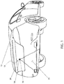
- FIG. 1 is a perspective view of a retractable weather shield 10 that is in accord with the present invention and which is installed on a motor vehicle 15 ;
- FIG. 2 is a front view of a retractable weather shield 10 installed on a rear-view camera mounted on a license plate trim ring 35 ;
- FIG. 3 is a sectional view of the retractable weather shield 10 taken along line I-I of FIG. 2 ;
- FIG. 4 is a sectional view of the retractable weather shield 10 taken along line II-II of FIG. 2 ;
- FIG. 5 is an electrical block diagram of the retractable weather shield 10 .
- FIGS. 1 through 5 The preferred embodiment of the present invention is depicted in FIGS. 1 through 5 .
- the invention is not limited to the specifically described embodiment.
- a person skilled in the art will appreciate that many other embodiments of the invention are possible without deviating from the basic concept of the invention, and that any such work around will fall within the scope of this invention.
- FIG. 1 for a front view of a retractable weather shield 10 that is in accord with the preferred embodiment of the present invention.
- the retractable weather shield 10 is mounted on a rear surface 20 of a motor vehicle 15 , such as on a trim area, a bumper area, a license plate trim ring (as shown on FIG. 2 ), an access handle, or the like.
- the retractable weather shield 10 might be provided as original equipment manufacturer (OEM) equipment or made available as an aftermarket add-on for installation by the user or some third party.
- OEM original equipment manufacturer
- the motor vehicle 15 is depicted as a sport utility vehicle (SUV).
- SUV sport utility vehicle
- other types of motor vehicle 15 including; but not limited to: sedans, pickup trucks, vans, semi's, and the like could also benefit from the teachings of the present invention.
- the use of the retractable weather shield 10 on any particular style, make, or model of motor vehicle 15 is not intended to be a limiting factor of the present invention.
- the rear-view camera 30 is located on the rear of the motor vehicle 15 so as to have a field of view 25 suitable for the intended purpose of the rear-view camera 30 .
- the retractable weather shield 10 can be an integral component of the rear-view camera 30 itself, it can be a separate component that is positioned over an existing rear-view camera 30 , it can be a housing for a rear-view camera 30 , or it can be an integral part of the motor vehicle 15 .
- FIG. 2 for a front view of a retractable weather shield 10 that is mounted on a license plate trim ring 35 .
- a retractable weather shield 10 that is part of a rear surface 20 of the motor vehicle 15 and thus is better-suited for OEM applications.
- the rear-view camera 30 is protected by a lower portion 40 of a weatherproof housing 45 , of the retractable weather shielded 10 .
- That weatherproof housing 45 further includes an upper portion 55 which houses internal electrical and mechanical components as are described below.
- the retractable weather shield 10 further includes a movable protective domed cover 50 which is selectively positioned either directly in front of closed position or above open position the view-port (lens system) of the rear-view camera 30 .
- the domed cover 50 When the rear-view camera 30 is not being used the domed cover 50 is moved downward to cover the lower portion 40 of the weatherproof housing 45 , and thus is positioned directly in front of the rear-view camera 30 in a closed position. This protects the rear-view camera 30 and its view-port from dirt, mud, road grit, dust, salt, insects, snow, and other unwanted contaminants by having such contaminants deposited on the domed cover 50 .
- FIG. 3 for a sectional view of the retractable weather shield 10 taken along line I-I of FIG. 2 .
- the domed cover 50 is opened by being flipped upward. This position would be taken when using the rear-view camera 30 such as when the motor vehicle 15 ( FIG. 1 ) is backing up or parking.
- a weatherproof gasket 60 is provided around the perimeter of the lower portion 40 of the weatherproof housing 45 .
- the weatherproof gasket 60 is envisioned to be rubber, silicone, or another suitable material which provides a weatherproof seal between the domed cover 50 and the lower portion 40 of the weatherproof housing 45 .
- a linear cleaning brush 65 shown at the top of a brush travel path “b” 70 , enables cleaning of the rear-view camera 30 whenever the domed cover 50 is moved.
- the brush travel path “b” 70 is established by vertical guide tracks 75 disposed along the sides of the lower portion 40 of the weatherproof housing 45 .
- FIG. 4 provides improved visual clarity on the electrical and mechanical components within the weatherproof housing 45 .
- the rear-view camera 30 is located within the lower portion 40 of the weatherproof housing 45 and has a weatherproof gasket 60 located around its perimeter.
- Inside the weatherproof housing 45 is an electric motor 110 having integral limit switches.
- the electric motor 110 drives a hinge linkage mechanism 115 from a raised linkage position 120 (as shown) to a lowered linkage position 125 which positions the domed cover 50 in a closed state (as shown in FIG. 1 and FIG. 2 ).
- the linkage mechanism 115 causes the cleaning brush 65 to travel along the guide tracks 75 . That linkage mechanism 115 is driven by a cable 80 which is wound around a reel 85 .
- the cable 80 moves the position of the cleaning brush 65 to an upper brush position 90 when the domed cover 50 is open.
- the cable 80 also moves the cleaning brush 65 to a lower brush position 95 when the domed cover 50 is closed.
- the domed cover 50 pivots on a hinge point 100 as the domed cover 50 moves along rotational travel path “r” 105 when transitioning between the open position (when the rear-view camera 30 is being utilized) and the closed position (when the rear-view camera 30 is not being utilized, but is being protected from buildup of road grit, dust, salt, insects, snow, and any unwanted contaminants).
- a connecting drive belt 130 coupled between the electric motor 110 and the reel 85 simultaneously drives the cleaning brush 65 , as described, when the domed cover 50 is being moved.
- FIG. 5 for an electrical block diagram of the retractable weather shield 10 .
- the rear-view camera 30 is connected to a 12 VDC supply 135 and to a camera video signal connection 140 . It is envisioned that the 12 VDC supply 135 is energized whenever the rear-view camera 30 is powered on, such as when the motor vehicle 15 ( FIG. 1 ) is in reverse.
- a motor control circuit 145 connects to the 12 VDC supply 135 via a splice point 150 either as part of the wiring harness or as part of an aftermarket add-on installation. The motor control circuit 145 conditions the electric motor 110 for operation as described above.
- the preferred embodiment of the present invention can be utilized by the common user in a simple and effortless manner with little or no training. It is envisioned that the retractable weather shield 10 would be constructed in general accordance with FIG. 1 through FIG. 5 . The user would procure the retractable weather shield 10 either as part of new vehicle purchase as OEM equipment or as an aftermarket add-on component for installation by the user or a skilled third party.
- the rear-view camera 30 would be positioned within the lower portion 40 of the weatherproof housing 45 ; the splice point 150 would be made in the 12 VDC supply 135 to connect the motor control circuit 145 ; and proper operation of the domed cover 50 would be verified.
- the connecting drive belt 130 is driven by the electric motor 110 to rotate the reel 85 and thus the cable 80 ; the cleaning brush 65 then travels along the guide tracks 75 as driven by the cable 80 to clean and wipe the rear-view camera 30 ; whereupon a video signal with no rearward obstructions is provided to existing on-board displays to aid in rearward vehicle guidance.
- the electric motor 110 is driven by the motor control circuit 145 to close the domed cover 50 ; simultaneously the connecting drive belt 130 is driven by the electric motor 110 to rotate the reel 85 and thus the cable 80 ; the cleaning brush 65 travels along the guide tracks 75 as driven by the cable 80 to clean and wipe the rear-view camera 30 and comes to rest at the upper brush position 90 .
- the domed cover 50 may be raised manually by hand to clean the rear-view camera 30 such as when washing the motor vehicle 15 or when needed for various reasons.
Abstract
A camera protection device, a protected camera and a vehicle having a protected camera, all include a weatherproof housing having a lower portion for holding a camera and an upper portion, a movable protective domed cover, and a mechanism for selectively moving the domed cover in front of the lower portion in a closed position or above the lower portion in an open position. The mechanism includes a motor that is operatively connected to the domed cover. A cleaning brush vertically wipes across the lower portion when the mechanism moves the domed cover. A seal seals between the domed cover and the lower portion when the domed portion is in front of the lower portion in a closed position. The mechanism includes a cable, a pivot for pivoting the domed cover, and a linkage connecting the motor to the domed cover. A belt operatively connects the motor to the linkage.
Description
The presently disclosed subject matter is directed to vehicle safety. More particularly the present invention relates to movable protective covers for vehicle rear-view cameras.
A popular option on late model motor vehicles is the rear-view camera. Rear-view cameras provide drivers with a view of areas behind their vehicles that rear-view mirrors cannot provide. Highly useful when backing up and parking, rear-view cameras are also safety features that help prevent accidents.
While popular and useful, rear-view cameras suffer from major disadvantages that can become readily apparent to those who use them. It only takes a small amount of road grit, dust, salt, insects, snow, and the like to render them almost or totally useless. Such contamination can occur during or after inclement weather or while experiencing dirty conditions.
Rear-view camera contamination can force users to either forgo the enhanced visual aid that comes from their use or to stop their vehicles to remove the offending materials. Contamination can become a never-ending battle while driving under conditions in which dirt, salt, dust, sleet and snow are experienced. A rear-view camera can become excessively blocked in a remarkably short time.
In the prior art some manufacturers provided washer systems that clean rear-view cameras. While useful, such washer systems take time to operate, can smear camera views and in general are not instantly available when a clear rearward view is needed.
Accordingly, there exists a need to protect motor vehicle rear-view cameras from contaminants such that unobstructed views can be made available on a moment's notice. Preferably such unobstructed views would be provided in a manner suitable for being implemented at low cost and in configurations that can be rapidly installed and easy to use. Ideally, such unobstructed views would be provided without limiting the camera view and without impeding access to the rear of the motor vehicle.
The principles of the present invention provide for protective devices for rear-view cameras, for rear-view cameras that incorporate such protection, and for motor vehicles having protected rear-view cameras. When using the subject invention unobstructed views can be made available on a moment's notice without limiting the camera view and without impeding access to the rear of the motor vehicle. The protective features are suitable for being implemented at low cost and in configurations that can be rapidly installed and easy to use.
A camera protection device in accord with the present invention includes a weatherproof housing having a lower portion for holding a camera and an upper portion, a movable protective domed cover, and a mechanism for selectively moving the domed cover in front of the lower portion or above the lower portion.
Beneficially the mechanism includes a motor that is operatively connected to the domed cover. Also, beneficially the camera protection device further includes a cleaning brush that vertically wipes across the lower portion when the mechanism moves the domed cover. Preferably, there is a seal for sealing between the domed cover and lower portion when the domed portion is in front of the lower portion in a closed position. The mechanism can further include a cable, a pivot for pivoting the domed cover, and a linkage connecting the motor to the domed cover. There may be a belt operatively connecting the motor to the linkage. Preferably, the mechanism is located inside the upper portion.
A camera that is in accord with the present invention includes a weatherproof housing having a lower portion and an upper portion, a camera body located in the lower portion, a movable protective domed cover, and a mechanism for selectively moving the domed cover in front of the camera body or over the camera body.
Beneficially, the mechanism includes a motor that is operatively connected to the domed cover. Also beneficially the camera further includes a cleaning brush that vertically wipes across the camera lens when the mechanism moves the domed cover. Preferably, there is a seal for sealing between the domed cover and lower portion when the domed portion is in front of the camera body in a closed position. The mechanism can further include a cable, a pivot for pivoting the domed cover, and a linkage connecting the motor to the domed cover. There may be a belt operatively connecting the motor to the linkage. Preferably, the mechanism is located inside the upper portion.
A motor vehicle that is in accord with the present invention includes a rear vehicle portion, a weatherproof housing attached to the rear vehicle portion, wherein the weather proof housing includes a lower portion and an upper portion, a camera body in the lower portion, a movable protective domed cover; and a mechanism for selectively moving the domed cover in front of the camera body in a closed position or above the camera body in an open position.
Beneficially the mechanism includes a motor that is operatively connected to the domed cover. Also, beneficially the mechanism includes a cleaning brush that vertically wipes across the camera lens when the mechanism moves the domed cover. Preferably, there is a seal for sealing between the domed cover and the lower portion when the domed portion is in front of the camera body in a closed position. The mechanism can further include a cable, a pivot for pivoting the domed cover, and a linkage connecting the motor to the domed cover. There may be a belt operatively connecting the motor to the linkage. Preferably, the mechanism is located inside the upper portion.
The advantages and features of the present invention will become better understood with reference to the following detailed description and claims when taken in conjunction with the accompanying drawings in which:
-
- 10 retractable weather shield
- 15 motor vehicle
- 20 rear facing surface
- 25 field of view
- 30 rear-view camera
- 35 license plate trim ring
- 40 lower portion
- 45 weatherproof housing
- 50 movable domed cover
- 55 upper portion
- 60 weatherproof gasket
- 65 cleaning brush
- 70 brush travel path “b”
- 75 guide track
- 80 cable
- 85 reel
- 90 upper brush position
- 95 lower brush position
- 100 hinge point
- 105 rotational travel path “r”
- 110 electric motor
- 115 hinge linkage mechanism
- 120 raised linkage position
- 125 lowered linkage position
- 130 connecting drive belt
- 135 12 VDC supply
- 140 camera video signal connection
- 145 motor control circuit
- 150 splice point
The preferred embodiment of the present invention is depicted in FIGS. 1 through 5 . However, the invention is not limited to the specifically described embodiment. A person skilled in the art will appreciate that many other embodiments of the invention are possible without deviating from the basic concept of the invention, and that any such work around will fall within the scope of this invention.
In the figures like numbers refer to like elements throughout. Additionally, the terms “a” and “an” as used herein do not denote a limitation of quantity, but rather denote the presence of at least one of the referenced items.
Refer now to FIG. 1 for a front view of a retractable weather shield 10 that is in accord with the preferred embodiment of the present invention. The retractable weather shield 10 is mounted on a rear surface 20 of a motor vehicle 15, such as on a trim area, a bumper area, a license plate trim ring (as shown on FIG. 2 ), an access handle, or the like. It is envisioned that the retractable weather shield 10 might be provided as original equipment manufacturer (OEM) equipment or made available as an aftermarket add-on for installation by the user or some third party.
For purposes of illustration the motor vehicle 15 is depicted as a sport utility vehicle (SUV). However, it is to be understood that other types of motor vehicle 15 including; but not limited to: sedans, pickup trucks, vans, semi's, and the like could also benefit from the teachings of the present invention. As such the use of the retractable weather shield 10 on any particular style, make, or model of motor vehicle 15 is not intended to be a limiting factor of the present invention.
Still referring to FIG. 1 , the rear-view camera 30 is located on the rear of the motor vehicle 15 so as to have a field of view 25 suitable for the intended purpose of the rear-view camera 30. It is envisioned that the retractable weather shield 10 can be an integral component of the rear-view camera 30 itself, it can be a separate component that is positioned over an existing rear-view camera 30, it can be a housing for a rear-view camera 30, or it can be an integral part of the motor vehicle 15.
Refer next to FIG. 2 for a front view of a retractable weather shield 10 that is mounted on a license plate trim ring 35. Such a placement is well-suited for aftermarket installation. This is in contrast to FIG. 1 which shows a retractable weather shield 10 that is part of a rear surface 20 of the motor vehicle 15 and thus is better-suited for OEM applications.
In any event the rear-view camera 30 is protected by a lower portion 40 of a weatherproof housing 45, of the retractable weather shielded 10. That weatherproof housing 45 further includes an upper portion 55 which houses internal electrical and mechanical components as are described below. The retractable weather shield 10 further includes a movable protective domed cover 50 which is selectively positioned either directly in front of closed position or above open position the view-port (lens system) of the rear-view camera 30.
When the rear-view camera 30 is not being used the domed cover 50 is moved downward to cover the lower portion 40 of the weatherproof housing 45, and thus is positioned directly in front of the rear-view camera 30 in a closed position. This protects the rear-view camera 30 and its view-port from dirt, mud, road grit, dust, salt, insects, snow, and other unwanted contaminants by having such contaminants deposited on the domed cover 50.
Refer now to FIG. 3 for a sectional view of the retractable weather shield 10 taken along line I-I of FIG. 2 . The domed cover 50 is opened by being flipped upward. This position would be taken when using the rear-view camera 30 such as when the motor vehicle 15 (FIG. 1 ) is backing up or parking. A weatherproof gasket 60 is provided around the perimeter of the lower portion 40 of the weatherproof housing 45. The weatherproof gasket 60 is envisioned to be rubber, silicone, or another suitable material which provides a weatherproof seal between the domed cover 50 and the lower portion 40 of the weatherproof housing 45.
Still referring to FIG. 3 , a linear cleaning brush 65, shown at the top of a brush travel path “b” 70, enables cleaning of the rear-view camera 30 whenever the domed cover 50 is moved. The brush travel path “b” 70 is established by vertical guide tracks 75 disposed along the sides of the lower portion 40 of the weatherproof housing 45.
Refer next to FIG. 4 for a sectional view taken along lines II-II of FIG. 2 . FIG. 4 provides improved visual clarity on the electrical and mechanical components within the weatherproof housing 45. As noted, the rear-view camera 30 is located within the lower portion 40 of the weatherproof housing 45 and has a weatherproof gasket 60 located around its perimeter. Inside the weatherproof housing 45 is an electric motor 110 having integral limit switches. The electric motor 110 drives a hinge linkage mechanism 115 from a raised linkage position 120 (as shown) to a lowered linkage position 125 which positions the domed cover 50 in a closed state (as shown in FIG. 1 and FIG. 2 ).
The linkage mechanism 115 causes the cleaning brush 65 to travel along the guide tracks 75. That linkage mechanism 115 is driven by a cable 80 which is wound around a reel 85. The cable 80 moves the position of the cleaning brush 65 to an upper brush position 90 when the domed cover 50 is open. The cable 80 also moves the cleaning brush 65 to a lower brush position 95 when the domed cover 50 is closed.
The domed cover 50 pivots on a hinge point 100 as the domed cover 50 moves along rotational travel path “r” 105 when transitioning between the open position (when the rear-view camera 30 is being utilized) and the closed position (when the rear-view camera 30 is not being utilized, but is being protected from buildup of road grit, dust, salt, insects, snow, and any unwanted contaminants). A connecting drive belt 130 coupled between the electric motor 110 and the reel 85 simultaneously drives the cleaning brush 65, as described, when the domed cover 50 is being moved.
Refer finally to FIG. 5 for an electrical block diagram of the retractable weather shield 10. The rear-view camera 30 is connected to a 12 VDC supply 135 and to a camera video signal connection 140. It is envisioned that the 12 VDC supply 135 is energized whenever the rear-view camera 30 is powered on, such as when the motor vehicle 15 (FIG. 1 ) is in reverse. A motor control circuit 145 connects to the 12 VDC supply 135 via a splice point 150 either as part of the wiring harness or as part of an aftermarket add-on installation. The motor control circuit 145 conditions the electric motor 110 for operation as described above.
The preferred embodiment of the present invention can be utilized by the common user in a simple and effortless manner with little or no training. It is envisioned that the retractable weather shield 10 would be constructed in general accordance with FIG. 1 through FIG. 5 . The user would procure the retractable weather shield 10 either as part of new vehicle purchase as OEM equipment or as an aftermarket add-on component for installation by the user or a skilled third party.
During installation the following process would be followed. The rear-view camera 30 would be positioned within the lower portion 40 of the weatherproof housing 45; the splice point 150 would be made in the 12 VDC supply 135 to connect the motor control circuit 145; and proper operation of the domed cover 50 would be verified.
During use the user or driver of the motor vehicle 15 would place the motor vehicle 15 in reverse; the energized 12 VDC supply 135 would drive the motor control circuit 145 and the electric motor 110 via power supplied by the splice point 150; the electric motor 110 would move the hinge linkage mechanism 115 into a raised linkage position 120, thus moving the domed cover 50 (FIG. 4 ) to an open position. Simultaneously, the connecting drive belt 130 is driven by the electric motor 110 to rotate the reel 85 and thus the cable 80; the cleaning brush 65 then travels along the guide tracks 75 as driven by the cable 80 to clean and wipe the rear-view camera 30; whereupon a video signal with no rearward obstructions is provided to existing on-board displays to aid in rearward vehicle guidance.
When the motor vehicle 15 is placed in a forward gear position the above process is reversed: the electric motor 110 is driven by the motor control circuit 145 to close the domed cover 50; simultaneously the connecting drive belt 130 is driven by the electric motor 110 to rotate the reel 85 and thus the cable 80; the cleaning brush 65 travels along the guide tracks 75 as driven by the cable 80 to clean and wipe the rear-view camera 30 and comes to rest at the upper brush position 90. It is also noted that the domed cover 50 may be raised manually by hand to clean the rear-view camera 30 such as when washing the motor vehicle 15 or when needed for various reasons.
The foregoing descriptions of an embodiment of the present invention were presented for purposes of illustration and description. They are not intended to be exhaustive or to limit the invention to the precise forms disclosed. Obviously, many modifications and variations are possible in light of the above teaching. The embodiment was chosen and described in order to best explain the principles of the invention and its practical application to thereby enable others skilled in the art to best utilize the invention and various embodiments with various modifications as are suited to the particular use contemplated.
Claims (14)
1. A camera protection device, comprising:
a weatherproof housing having a lower portion for holding a camera and an upper portion;
a movable protective domed cover;
a mechanism for selectively moving said domed cover in front of the lower portion in a closed position or above the lower portion in an open position; and,
a cleaning brush that vertically wipes across said lower portion when said mechanism moves said domed cover,
wherein said mechanism includes a motor operatively connected to said domed cover.
2. The camera protection device according to claim 1 , further includes a seal for sealing between said domed cover and said lower portion when said a domed portion is in front of said lower portion in a closed position.
3. The camera protection device according to claim 1 , wherein said mechanism further includes a cable, a pivot for said domed cover, and a linkage connecting said motor to said domed cover.
4. The camera protection device according to claim 3 , further includes a belt operatively connecting said motor to said linkage.
5. The camera protection device according to claim 4 , wherein said mechanism is located inside said upper portion.
6. A camera, comprising:
a weatherproof housing having a lower portion and an upper portion;
a camera body in said lower portion;
a movable protective domed cover;
a mechanism for selectively moving said domed cover in front of the camera body or above the camera body; and,
a cleaning brush that vertically wipes across said lower portion when said mechanism moves said domed cover,
wherein said mechanism includes a motor operatively connected to said domed cover.
7. The camera protection device according to claim 6 , further includes a seal for sealing between said domed cover and said lower portion when a domed portion is in front of the camera body in a closed position.
8. The camera according to claim 6 , wherein said mechanism further includes a cable, a pivot for said domed cover, and a linkage connecting said motor to said domed cover.
9. The camera according to claim 8 , further includes a belt operatively connecting said motor to said linkage.
10. A motor vehicle, comprising:
a rear vehicle portion;
a weatherproof housing disposed on said rear vehicle portion, said weather proof housing having a lower portion and an upper portion;
a camera body in said lower portion;
a movable protective domed cover;
a mechanism for selectively moving said domed cover in front of the camera body or over the camera body; and,
a cleaning brush that vertically wipes across said lower portion when said mechanism moves said domed cover,
wherein said mechanism includes a motor operatively connected to said domed cover.
11. The motor vehicle protection device according to claim 10 , further includes a seal for sealing between said domed cover and said lower portion when a domed portion is in front of the camera body in a closed position.
12. The motor vehicle according to claim 10 , wherein said mechanism further includes a cable, a pivot for said domed cover, and a linkage connecting said motor to said domed cover.
13. The motor vehicle according to claim 12 , further includes a belt operatively connecting said motor to said linkage.
14. The motor vehicle according to claim 13 , wherein said mechanism is located inside said upper portion.
Priority Applications (1)
| Application Number | Priority Date | Filing Date | Title |
|---|---|---|---|
| US16/267,496 US10606151B1 (en) | 2019-02-05 | 2019-02-05 | Cover for rear-mounted vehicle camera |
Applications Claiming Priority (1)
| Application Number | Priority Date | Filing Date | Title |
|---|---|---|---|
| US16/267,496 US10606151B1 (en) | 2019-02-05 | 2019-02-05 | Cover for rear-mounted vehicle camera |
Publications (1)
| Publication Number | Publication Date |
|---|---|
| US10606151B1 true US10606151B1 (en) | 2020-03-31 |
Family
ID=69951535
Family Applications (1)
| Application Number | Title | Priority Date | Filing Date |
|---|---|---|---|
| US16/267,496 Active US10606151B1 (en) | 2019-02-05 | 2019-02-05 | Cover for rear-mounted vehicle camera |
Country Status (1)
| Country | Link |
|---|---|
| US (1) | US10606151B1 (en) |
Cited By (4)
| Publication number | Priority date | Publication date | Assignee | Title |
|---|---|---|---|---|
| CN112108415A (en) * | 2020-09-16 | 2020-12-22 | 柳州银联电子科技有限公司 | Intelligent collision-prevention early warning monitoring equipment for automobile |
| CN112449039A (en) * | 2020-06-30 | 2021-03-05 | 上海福赛梦扬科技有限公司 | Cell-phone camera structure that protection camera and multi-angle were shot |
| US11226540B2 (en) | 2019-07-10 | 2022-01-18 | Danny Ray Duke | Shield for an exterior vehicular component |
| US20220222805A1 (en) * | 2014-09-17 | 2022-07-14 | Gary B. Levin | Apparatus and method for onboard stereoscopic inspection of vehicle tires |
Citations (9)
| Publication number | Priority date | Publication date | Assignee | Title |
|---|---|---|---|---|
| US7813639B2 (en) | 2005-04-20 | 2010-10-12 | Autonetworks Technologies, Ltd. | Camera cover |
| US9291879B2 (en) | 2014-08-25 | 2016-03-22 | Ford Global Technologies, Llc | Hidden camera system for vehicle |
| US9298065B1 (en) | 2014-12-01 | 2016-03-29 | Ford Global Technologies, Pllc | Hidden camera system with enclosure incorporating a flexible seal |
| US9444984B2 (en) | 2010-06-11 | 2016-09-13 | Huf Hulsbeck & Furst Gmbh & Co. Kg | Device having a camera unit |
| US9442350B2 (en) | 2014-12-04 | 2016-09-13 | Ford Global Technologies, Llc | Hidden camera assembly with microprocessor control |
| US20170036600A1 (en) * | 2015-08-03 | 2017-02-09 | Velvac Incorporated | Dual camera fifth wheel system and method |
| US9744914B2 (en) | 2011-04-05 | 2017-08-29 | Huf Hulsbeck & Furst Gmbh & Co. Kg | Device for a vehicle having a camera unit located in a protective housing |
| US9866736B2 (en) | 2013-04-18 | 2018-01-09 | Huf Hulsbeck & Furst Gmbh & Co. Kg | Device having a camera unit and a double-walled housing |
| US9955052B2 (en) | 2015-04-24 | 2018-04-24 | Huf Huelsbeck & Fuerst Gmbh & Co. Kg | Device having a camera unit and a cover element |
-
2019
- 2019-02-05 US US16/267,496 patent/US10606151B1/en active Active
Patent Citations (11)
| Publication number | Priority date | Publication date | Assignee | Title |
|---|---|---|---|---|
| US7813639B2 (en) | 2005-04-20 | 2010-10-12 | Autonetworks Technologies, Ltd. | Camera cover |
| US9444984B2 (en) | 2010-06-11 | 2016-09-13 | Huf Hulsbeck & Furst Gmbh & Co. Kg | Device having a camera unit |
| US9531924B2 (en) | 2010-06-11 | 2016-12-27 | Huf Hulsbeck & Furst Gmbh & Co. Kg | Device having a camera unit |
| US9584706B2 (en) | 2010-06-11 | 2017-02-28 | Huf Hulsbeck & Furst Gmbh & Co. Kg | Device having a camera unit |
| US9744914B2 (en) | 2011-04-05 | 2017-08-29 | Huf Hulsbeck & Furst Gmbh & Co. Kg | Device for a vehicle having a camera unit located in a protective housing |
| US9866736B2 (en) | 2013-04-18 | 2018-01-09 | Huf Hulsbeck & Furst Gmbh & Co. Kg | Device having a camera unit and a double-walled housing |
| US9291879B2 (en) | 2014-08-25 | 2016-03-22 | Ford Global Technologies, Llc | Hidden camera system for vehicle |
| US9298065B1 (en) | 2014-12-01 | 2016-03-29 | Ford Global Technologies, Pllc | Hidden camera system with enclosure incorporating a flexible seal |
| US9442350B2 (en) | 2014-12-04 | 2016-09-13 | Ford Global Technologies, Llc | Hidden camera assembly with microprocessor control |
| US9955052B2 (en) | 2015-04-24 | 2018-04-24 | Huf Huelsbeck & Fuerst Gmbh & Co. Kg | Device having a camera unit and a cover element |
| US20170036600A1 (en) * | 2015-08-03 | 2017-02-09 | Velvac Incorporated | Dual camera fifth wheel system and method |
Cited By (4)
| Publication number | Priority date | Publication date | Assignee | Title |
|---|---|---|---|---|
| US20220222805A1 (en) * | 2014-09-17 | 2022-07-14 | Gary B. Levin | Apparatus and method for onboard stereoscopic inspection of vehicle tires |
| US11226540B2 (en) | 2019-07-10 | 2022-01-18 | Danny Ray Duke | Shield for an exterior vehicular component |
| CN112449039A (en) * | 2020-06-30 | 2021-03-05 | 上海福赛梦扬科技有限公司 | Cell-phone camera structure that protection camera and multi-angle were shot |
| CN112108415A (en) * | 2020-09-16 | 2020-12-22 | 柳州银联电子科技有限公司 | Intelligent collision-prevention early warning monitoring equipment for automobile |
Similar Documents
| Publication | Publication Date | Title |
|---|---|---|
| US10606151B1 (en) | Cover for rear-mounted vehicle camera | |
| CN108349440B (en) | Mobile image recording device and vehicle provided with such a device | |
| CA2726186C (en) | Side mirror system with video display | |
| US7355629B2 (en) | Internally mounted, movable camera for vehicles | |
| US6819231B2 (en) | Parking and/or maneuvering assistance device | |
| US6151065A (en) | Concealed integrated vehicular camera safety system | |
| EP0711681B1 (en) | Back-vision system for vehicles | |
| US4277804A (en) | System for viewing the area rearwardly of a vehicle | |
| US20070103780A1 (en) | Optical surface clearing arrangement | |
| KR20180102462A (en) | Apparatus Cleaning Dust of Moving Camera Lens | |
| US3704063A (en) | Rearview mirror device | |
| CN110861582B (en) | Vehicle image pickup unit | |
| JPH0450041A (en) | Car with video camera | |
| CN211726709U (en) | Vehicle-mounted camera cleaning device | |
| WO1998046452A1 (en) | A rearview mirror shielding device | |
| KR102661601B1 (en) | Mobile image recording devices and vehicles provided with such devices | |
| JP6552559B2 (en) | Camera monitoring system | |
| EP3632748A1 (en) | Rear view assembly and vehicle with such rear view assembly | |
| JPH04175072A (en) | Monitoring camera device | |
| KR200342863Y1 (en) | Rainwater interception type rear mirror | |
| TR201805479U5 (en) | HEAVY DUTY MIRROR WITH WIPER | |
| JPH06255453A (en) | Waterdrop preventive device of rear view mirror | |
| KR19980058616A (en) | Side mirror with automatic dedusting device | |
| JPH0625064U (en) | In-vehicle surveillance camera | |
| CN117302114A (en) | Sensor cleaning device |
Legal Events
| Date | Code | Title | Description |
|---|---|---|---|
| FEPP | Fee payment procedure |
Free format text: ENTITY STATUS SET TO UNDISCOUNTED (ORIGINAL EVENT CODE: BIG.); ENTITY STATUS OF PATENT OWNER: MICROENTITY |
|
| FEPP | Fee payment procedure |
Free format text: ENTITY STATUS SET TO MICRO (ORIGINAL EVENT CODE: MICR); ENTITY STATUS OF PATENT OWNER: MICROENTITY |
|
| FEPP | Fee payment procedure |
Free format text: ENTITY STATUS SET TO MICRO (ORIGINAL EVENT CODE: MICR); ENTITY STATUS OF PATENT OWNER: MICROENTITY |
|
| STCF | Information on status: patent grant |
Free format text: PATENTED CASE |
|
| FEPP | Fee payment procedure |
Free format text: MAINTENANCE FEE REMINDER MAILED (ORIGINAL EVENT CODE: REM.); ENTITY STATUS OF PATENT OWNER: MICROENTITY |