US10603832B2 - Die with aligning mechanism, and manufacturing device and method for enameled wire - Google Patents
Die with aligning mechanism, and manufacturing device and method for enameled wire Download PDFInfo
- Publication number
- US10603832B2 US10603832B2 US15/892,559 US201815892559A US10603832B2 US 10603832 B2 US10603832 B2 US 10603832B2 US 201815892559 A US201815892559 A US 201815892559A US 10603832 B2 US10603832 B2 US 10603832B2
- Authority
- US
- United States
- Prior art keywords
- die
- traveling wire
- wire
- traveling
- travel direction
- Prior art date
- Legal status (The legal status is an assumption and is not a legal conclusion. Google has not performed a legal analysis and makes no representation as to the accuracy of the status listed.)
- Active
Links
- 230000007246 mechanism Effects 0.000 title claims abstract description 66
- 238000004519 manufacturing process Methods 0.000 title claims description 39
- 238000000034 method Methods 0.000 title description 7
- 230000002401 inhibitory effect Effects 0.000 claims abstract description 8
- 239000011248 coating agent Substances 0.000 claims description 66
- 238000000576 coating method Methods 0.000 claims description 66
- 239000000463 material Substances 0.000 claims description 49
- 230000008859 change Effects 0.000 description 9
- 230000008569 process Effects 0.000 description 6
- 238000005096 rolling process Methods 0.000 description 5
- 239000004020 conductor Substances 0.000 description 4
- 238000009413 insulation Methods 0.000 description 4
- 239000010410 layer Substances 0.000 description 4
- 239000002966 varnish Substances 0.000 description 4
- 238000000137 annealing Methods 0.000 description 3
- 229910052751 metal Inorganic materials 0.000 description 3
- 239000002184 metal Substances 0.000 description 3
- 239000002344 surface layer Substances 0.000 description 3
- 238000005491 wire drawing Methods 0.000 description 3
- RYGMFSIKBFXOCR-UHFFFAOYSA-N Copper Chemical compound [Cu] RYGMFSIKBFXOCR-UHFFFAOYSA-N 0.000 description 2
- XEEYBQQBJWHFJM-UHFFFAOYSA-N Iron Chemical compound [Fe] XEEYBQQBJWHFJM-UHFFFAOYSA-N 0.000 description 2
- 229910052782 aluminium Inorganic materials 0.000 description 2
- XAGFODPZIPBFFR-UHFFFAOYSA-N aluminium Chemical compound [Al] XAGFODPZIPBFFR-UHFFFAOYSA-N 0.000 description 2
- 238000010586 diagram Methods 0.000 description 2
- 230000000694 effects Effects 0.000 description 2
- 239000004962 Polyamide-imide Substances 0.000 description 1
- 239000004642 Polyimide Substances 0.000 description 1
- 229910052802 copper Inorganic materials 0.000 description 1
- 239000010949 copper Substances 0.000 description 1
- 230000008021 deposition Effects 0.000 description 1
- 238000006073 displacement reaction Methods 0.000 description 1
- 239000002320 enamel (paints) Substances 0.000 description 1
- 238000010438 heat treatment Methods 0.000 description 1
- 229910052742 iron Inorganic materials 0.000 description 1
- 238000003754 machining Methods 0.000 description 1
- 239000007769 metal material Substances 0.000 description 1
- 238000012986 modification Methods 0.000 description 1
- 230000004048 modification Effects 0.000 description 1
- 230000002093 peripheral effect Effects 0.000 description 1
- 229920003055 poly(ester-imide) Polymers 0.000 description 1
- 229920002312 polyamide-imide Polymers 0.000 description 1
- 229920001721 polyimide Polymers 0.000 description 1
- 229920005989 resin Polymers 0.000 description 1
- 239000011347 resin Substances 0.000 description 1
- 238000007493 shaping process Methods 0.000 description 1
Images


Classifications
-
- B—PERFORMING OPERATIONS; TRANSPORTING
- B29—WORKING OF PLASTICS; WORKING OF SUBSTANCES IN A PLASTIC STATE IN GENERAL
- B29C—SHAPING OR JOINING OF PLASTICS; SHAPING OF MATERIAL IN A PLASTIC STATE, NOT OTHERWISE PROVIDED FOR; AFTER-TREATMENT OF THE SHAPED PRODUCTS, e.g. REPAIRING
- B29C48/00—Extrusion moulding, i.e. expressing the moulding material through a die or nozzle which imparts the desired form; Apparatus therefor
- B29C48/25—Component parts, details or accessories; Auxiliary operations
- B29C48/30—Extrusion nozzles or dies
-
- B—PERFORMING OPERATIONS; TRANSPORTING
- B29—WORKING OF PLASTICS; WORKING OF SUBSTANCES IN A PLASTIC STATE IN GENERAL
- B29C—SHAPING OR JOINING OF PLASTICS; SHAPING OF MATERIAL IN A PLASTIC STATE, NOT OTHERWISE PROVIDED FOR; AFTER-TREATMENT OF THE SHAPED PRODUCTS, e.g. REPAIRING
- B29C48/00—Extrusion moulding, i.e. expressing the moulding material through a die or nozzle which imparts the desired form; Apparatus therefor
- B29C48/03—Extrusion moulding, i.e. expressing the moulding material through a die or nozzle which imparts the desired form; Apparatus therefor characterised by the shape of the extruded material at extrusion
- B29C48/06—Rod-shaped
-
- H—ELECTRICITY
- H01—ELECTRIC ELEMENTS
- H01B—CABLES; CONDUCTORS; INSULATORS; SELECTION OF MATERIALS FOR THEIR CONDUCTIVE, INSULATING OR DIELECTRIC PROPERTIES
- H01B13/00—Apparatus or processes specially adapted for manufacturing conductors or cables
- H01B13/06—Insulating conductors or cables
- H01B13/065—Insulating conductors with lacquers or enamels
-
- B—PERFORMING OPERATIONS; TRANSPORTING
- B29—WORKING OF PLASTICS; WORKING OF SUBSTANCES IN A PLASTIC STATE IN GENERAL
- B29C—SHAPING OR JOINING OF PLASTICS; SHAPING OF MATERIAL IN A PLASTIC STATE, NOT OTHERWISE PROVIDED FOR; AFTER-TREATMENT OF THE SHAPED PRODUCTS, e.g. REPAIRING
- B29C48/00—Extrusion moulding, i.e. expressing the moulding material through a die or nozzle which imparts the desired form; Apparatus therefor
- B29C48/15—Extrusion moulding, i.e. expressing the moulding material through a die or nozzle which imparts the desired form; Apparatus therefor incorporating preformed parts or layers, e.g. extrusion moulding around inserts
- B29C48/154—Coating solid articles, i.e. non-hollow articles
-
- B—PERFORMING OPERATIONS; TRANSPORTING
- B29—WORKING OF PLASTICS; WORKING OF SUBSTANCES IN A PLASTIC STATE IN GENERAL
- B29C—SHAPING OR JOINING OF PLASTICS; SHAPING OF MATERIAL IN A PLASTIC STATE, NOT OTHERWISE PROVIDED FOR; AFTER-TREATMENT OF THE SHAPED PRODUCTS, e.g. REPAIRING
- B29C48/00—Extrusion moulding, i.e. expressing the moulding material through a die or nozzle which imparts the desired form; Apparatus therefor
- B29C48/15—Extrusion moulding, i.e. expressing the moulding material through a die or nozzle which imparts the desired form; Apparatus therefor incorporating preformed parts or layers, e.g. extrusion moulding around inserts
- B29C48/156—Coating two or more articles simultaneously
-
- B—PERFORMING OPERATIONS; TRANSPORTING
- B29—WORKING OF PLASTICS; WORKING OF SUBSTANCES IN A PLASTIC STATE IN GENERAL
- B29C—SHAPING OR JOINING OF PLASTICS; SHAPING OF MATERIAL IN A PLASTIC STATE, NOT OTHERWISE PROVIDED FOR; AFTER-TREATMENT OF THE SHAPED PRODUCTS, e.g. REPAIRING
- B29C48/00—Extrusion moulding, i.e. expressing the moulding material through a die or nozzle which imparts the desired form; Apparatus therefor
- B29C48/25—Component parts, details or accessories; Auxiliary operations
- B29C48/30—Extrusion nozzles or dies
- B29C48/32—Extrusion nozzles or dies with annular openings, e.g. for forming tubular articles
- B29C48/34—Cross-head annular extrusion nozzles, i.e. for simultaneously receiving moulding material and the preform to be coated
-
- H—ELECTRICITY
- H01—ELECTRIC ELEMENTS
- H01B—CABLES; CONDUCTORS; INSULATORS; SELECTION OF MATERIALS FOR THEIR CONDUCTIVE, INSULATING OR DIELECTRIC PROPERTIES
- H01B13/00—Apparatus or processes specially adapted for manufacturing conductors or cables
- H01B13/0036—Details
-
- B—PERFORMING OPERATIONS; TRANSPORTING
- B05—SPRAYING OR ATOMISING IN GENERAL; APPLYING FLUENT MATERIALS TO SURFACES, IN GENERAL
- B05C—APPARATUS FOR APPLYING FLUENT MATERIALS TO SURFACES, IN GENERAL
- B05C11/00—Component parts, details or accessories not specifically provided for in groups B05C1/00 - B05C9/00
- B05C11/02—Apparatus for spreading or distributing liquids or other fluent materials already applied to a surface ; Controlling means therefor; Control of the thickness of a coating by spreading or distributing liquids or other fluent materials already applied to the coated surface
- B05C11/021—Apparatus for spreading or distributing liquids or other fluent materials already applied to the surface of an elongated body, e.g. a wire, a tube
-
- B—PERFORMING OPERATIONS; TRANSPORTING
- B05—SPRAYING OR ATOMISING IN GENERAL; APPLYING FLUENT MATERIALS TO SURFACES, IN GENERAL
- B05C—APPARATUS FOR APPLYING FLUENT MATERIALS TO SURFACES, IN GENERAL
- B05C3/00—Apparatus in which the work is brought into contact with a bulk quantity of liquid or other fluent material
- B05C3/02—Apparatus in which the work is brought into contact with a bulk quantity of liquid or other fluent material the work being immersed in the liquid or other fluent material
- B05C3/12—Apparatus in which the work is brought into contact with a bulk quantity of liquid or other fluent material the work being immersed in the liquid or other fluent material for treating work of indefinite length
- B05C3/15—Apparatus in which the work is brought into contact with a bulk quantity of liquid or other fluent material the work being immersed in the liquid or other fluent material for treating work of indefinite length not supported on conveying means
-
- B—PERFORMING OPERATIONS; TRANSPORTING
- B05—SPRAYING OR ATOMISING IN GENERAL; APPLYING FLUENT MATERIALS TO SURFACES, IN GENERAL
- B05C—APPARATUS FOR APPLYING FLUENT MATERIALS TO SURFACES, IN GENERAL
- B05C5/00—Apparatus in which liquid or other fluent material is projected, poured or allowed to flow on to the surface of the work
- B05C5/02—Apparatus in which liquid or other fluent material is projected, poured or allowed to flow on to the surface of the work the liquid or other fluent material being discharged through an outlet orifice by pressure, e.g. from an outlet device in contact or almost in contact, with the work
- B05C5/0241—Apparatus in which liquid or other fluent material is projected, poured or allowed to flow on to the surface of the work the liquid or other fluent material being discharged through an outlet orifice by pressure, e.g. from an outlet device in contact or almost in contact, with the work for applying liquid or other fluent material to elongated work, e.g. wires, cables, tubes
-
- B—PERFORMING OPERATIONS; TRANSPORTING
- B05—SPRAYING OR ATOMISING IN GENERAL; APPLYING FLUENT MATERIALS TO SURFACES, IN GENERAL
- B05D—PROCESSES FOR APPLYING FLUENT MATERIALS TO SURFACES, IN GENERAL
- B05D1/00—Processes for applying liquids or other fluent materials
- B05D1/26—Processes for applying liquids or other fluent materials performed by applying the liquid or other fluent material from an outlet device in contact with, or almost in contact with, the surface
- B05D1/265—Extrusion coatings
-
- B—PERFORMING OPERATIONS; TRANSPORTING
- B05—SPRAYING OR ATOMISING IN GENERAL; APPLYING FLUENT MATERIALS TO SURFACES, IN GENERAL
- B05D—PROCESSES FOR APPLYING FLUENT MATERIALS TO SURFACES, IN GENERAL
- B05D1/00—Processes for applying liquids or other fluent materials
- B05D1/40—Distributing applied liquids or other fluent materials by members moving relatively to surface
-
- B—PERFORMING OPERATIONS; TRANSPORTING
- B05—SPRAYING OR ATOMISING IN GENERAL; APPLYING FLUENT MATERIALS TO SURFACES, IN GENERAL
- B05D—PROCESSES FOR APPLYING FLUENT MATERIALS TO SURFACES, IN GENERAL
- B05D7/00—Processes, other than flocking, specially adapted for applying liquids or other fluent materials to particular surfaces or for applying particular liquids or other fluent materials
- B05D7/20—Processes, other than flocking, specially adapted for applying liquids or other fluent materials to particular surfaces or for applying particular liquids or other fluent materials to wires
-
- B—PERFORMING OPERATIONS; TRANSPORTING
- B29—WORKING OF PLASTICS; WORKING OF SUBSTANCES IN A PLASTIC STATE IN GENERAL
- B29C—SHAPING OR JOINING OF PLASTICS; SHAPING OF MATERIAL IN A PLASTIC STATE, NOT OTHERWISE PROVIDED FOR; AFTER-TREATMENT OF THE SHAPED PRODUCTS, e.g. REPAIRING
- B29C48/00—Extrusion moulding, i.e. expressing the moulding material through a die or nozzle which imparts the desired form; Apparatus therefor
- B29C48/25—Component parts, details or accessories; Auxiliary operations
- B29C48/30—Extrusion nozzles or dies
- B29C48/302—Extrusion nozzles or dies being adjustable, i.e. having adjustable exit sections
-
- B—PERFORMING OPERATIONS; TRANSPORTING
- B29—WORKING OF PLASTICS; WORKING OF SUBSTANCES IN A PLASTIC STATE IN GENERAL
- B29K—INDEXING SCHEME ASSOCIATED WITH SUBCLASSES B29B, B29C OR B29D, RELATING TO MOULDING MATERIALS OR TO MATERIALS FOR MOULDS, REINFORCEMENTS, FILLERS OR PREFORMED PARTS, e.g. INSERTS
- B29K2705/00—Use of metals, their alloys or their compounds, for preformed parts, e.g. for inserts
-
- H—ELECTRICITY
- H01—ELECTRIC ELEMENTS
- H01B—CABLES; CONDUCTORS; INSULATORS; SELECTION OF MATERIALS FOR THEIR CONDUCTIVE, INSULATING OR DIELECTRIC PROPERTIES
- H01B13/00—Apparatus or processes specially adapted for manufacturing conductors or cables
- H01B13/06—Insulating conductors or cables
- H01B13/16—Insulating conductors or cables by passing through or dipping in a liquid bath; by spraying
-
- Y—GENERAL TAGGING OF NEW TECHNOLOGICAL DEVELOPMENTS; GENERAL TAGGING OF CROSS-SECTIONAL TECHNOLOGIES SPANNING OVER SEVERAL SECTIONS OF THE IPC; TECHNICAL SUBJECTS COVERED BY FORMER USPC CROSS-REFERENCE ART COLLECTIONS [XRACs] AND DIGESTS
- Y10—TECHNICAL SUBJECTS COVERED BY FORMER USPC
- Y10S—TECHNICAL SUBJECTS COVERED BY FORMER USPC CROSS-REFERENCE ART COLLECTIONS [XRACs] AND DIGESTS
- Y10S118/00—Coating apparatus
- Y10S118/18—Wire and cord die
-
- Y—GENERAL TAGGING OF NEW TECHNOLOGICAL DEVELOPMENTS; GENERAL TAGGING OF CROSS-SECTIONAL TECHNOLOGIES SPANNING OVER SEVERAL SECTIONS OF THE IPC; TECHNICAL SUBJECTS COVERED BY FORMER USPC CROSS-REFERENCE ART COLLECTIONS [XRACs] AND DIGESTS
- Y10—TECHNICAL SUBJECTS COVERED BY FORMER USPC
- Y10S—TECHNICAL SUBJECTS COVERED BY FORMER USPC CROSS-REFERENCE ART COLLECTIONS [XRACs] AND DIGESTS
- Y10S118/00—Coating apparatus
- Y10S118/22—Wire and cord miscellaneous
Definitions
- the invention relates to a die with alignment mechanism, an enameled wire manufacturing equipment, and an enameled wire manufacturing method.
- a varnish layer is formed by applying a coating material such as insulating coating material around a metal wire rod (traveling wire) formed of, e.g., copper or aluminum (see, e.g., JP 2014/144384 A).
- a coating material applicator used to form such varnish layer has an applicator portion for applying a coating material to a surface of the traveling wire and a die with a through-hole for passing the traveling wire through.
- this coating material applicator when the traveling wire with a coating material applied by the applicator portion passes through the through-hole, an excessive coating material applied to the surface of the traveling wire is removed and a thickness of the coating material is thereby adjusted.
- the traveling wire pass through the center of the through-hole of the die.
- the traveling wire may, e.g., vibrate or twist or, in the horizontal-type equipment, become a catenary shape under its own weight. Due to such vibration, twist or catenary shape of the traveling wire, it is difficult to feed the traveling wire so as to pass through the center of the through-hole of the die.
- a process of forming the shape and diameter of the traveling wire is performed by a wire drawing machine or a rolling mill.
- a process of forming the shape and diameter of the traveling wire and the process of forming a varnish layer by applying a coating material are performed in the same production line, vibration or twist, etc., of the traveling wire sometimes occurs due to a difference in the travel speed, etc., of the traveling wire between the processes, resulting in that the traveling wire is less likely to pass through the center of the through-hole of the die.
- a die with alignment mechanism comprising:
- a die comprising a through-hole through which a traveling wire travels
- a movable member that moves the die so that a central axis of the through-hole is aligned with a travel direction of the traveling wire without inhibiting the rotational movement of the die produced by the bearing member when the travel direction changes in a direction orthogonal to the travel direction.
- a die with alignment mechanism wherein the movable member comprises a main body and a movable portion, the main body comprising a recessed portion for fitting the bearing member and a hole portion provided on a bottom surface of the recessed portion to allow a portion of the die to penetrate through, and the movable portion being arranged on the forward side of the main body in the travel direction to move the main body in a direction orthogonal to the travel direction of the traveling wire.
- a die with alignment mechanism wherein the die has one end face and another end face opposite thereto and comprises a flange portion including the one end face and a stem portion including the other end face and extending from the flange portion, and the though-hole is provided from the one end face to the other end face.
- a die with alignment mechanism wherein the bearing member comprises a bearing portion for rotationally moving the die in the circumferential direction of the traveling wire and has an annular outer shape.
- a die with alignment mechanism further comprising a receiving member that is arranged between the movable member and the die and comprises a raised portion protruding in the travel direction of the traveling wire and abutting against the bearing member.
- a die with alignment mechanism further comprising a guide member that is arranged to be in contact with the movable member and comprises a guide surface for guiding the movable member.
- a die with alignment mechanism wherein the movable portion of the movable member comprises rollers.
- a die with alignment mechanism wherein the movable portion of the movable member comprises ball rollers.
- a die with alignment mechanism wherein the receiving member is configured that the raised portion is provided on the base that is arranged adjacent to the flange portion of the die.
- a die with alignment mechanism wherein the receiving member is configured that the base has a larger outer diameter than the flange portion.
- a die with alignment mechanism wherein the guide member comprises an opening.
- an enameled wire manufacturing equipment comprising:
- a coating application mechanism for applying a coating material around a traveling wire
- a die with alignment mechanism that is arranged on the forward side of the coating application mechanism and comprises a die comprising a through-hole through which a traveling wire travels, a bearing member for rotationally moving the die in a circumferential direction of the traveling wire, and a movable member that moves the die so that a central axis of the through-hole is aligned with a travel direction of the traveling wire without inhibiting the rotational movement of the die produced by the bearing member when the travel direction changes in a direction orthogonal to the travel direction.
- an enameled wire manufacturing method comprising:
- a die with alignment mechanism that comprises a die comprising a through-hole through which a traveling wire travels, a bearing member for rotationally moving the die in a circumferential direction of the traveling wire, and a movable member that moves the die so that a central axis of the through-hole is aligned with a travel direction of the traveling wire without inhibiting the rotational movement of the die produced by the bearing member when the travel direction changes in a direction orthogonal to the travel direction.
- a die with alignment mechanism can be provided that allows a traveling wire to easily pass through a center of a through-hole of the die in a horizontal-type equipment, as well as an enameled wire manufacturing equipment and an enameled wire manufacturing method which use the die with alignment mechanism.
- FIGS. 1A and 1B are schematic diagrams illustrating a general configuration of an enameled wire manufacturing equipment in the first (or second) embodiment of the present invention
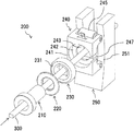
- FIG. 2 is an exploded perspective view showing a configuration of a die with alignment mechanism mounted on the enameled wire manufacturing equipment in the first embodiment
- FIG. 3 is a side view showing the configuration of the die with alignment mechanism mounted on the enameled wire manufacturing equipment in the first embodiment
- FIG. 4 is a side view showing a configuration of a die with alignment mechanism mounted on the enameled wire manufacturing equipment in the second embodiment.
- FIGS. 5A and 5B are cross sectional views showing configurations of enameled wires.
- FIGS. 1A and 1B are schematic diagrams illustrating a general configuration of the enameled wire manufacturing equipment 100 .
- the equipment described in the first embodiment is a horizontal-type enameled wire manufacturing equipment configured to apply a coating material to a substantially horizontally traveling wire, and is not a vertical-type enameled wire manufacturing equipment configured to apply a coating material to a substantially vertically traveling wire.
- the horizontal-type enameled wire manufacturing equipment is sometimes referred to as “a horizontal-type equipment”.
- the enameled wire manufacturing equipment 100 has a feeder 110 , a coating application unit 120 , a curing furnace 130 , a winder 140 , and pulleys 150 and 151 .
- a traveling wire 300 comprising a conductor formed of a metal rod is fed from the feeder 110 .
- the travel direction of the traveling wire 300 is indicated by arrows.
- a right-left direction on the paper of FIG. 1 is a horizontal direction.
- FIGS. 5A and 5B show cross sections of example enameled wires obtained in the first embodiment, wherein FIG. 5A shows an example enameled wire (insulated wire, covered wire) 320 having an insulation cover 310 around a rectangular conductor 301 and FIG. 5B shows an example enameled wire (insulated wire, covered wire) 320 formed by providing the insulation cover 310 around a round conductor 301 .
- the traveling wire 300 fed from the feeder 110 is conveyed into the coating application unit 120 .
- an insulating coating material is applied to the outer surface of the traveling wire 300 , and the thickness and shape of the applied insulating coating material are adjusted to a predetermined thickness and shape by a die with alignment mechanism (described later).
- the coating material used here can be appropriately selected from enamel coating materials containing resins formed of polyimide, polyamide-imide and polyester-imide, etc.
- the traveling wire 300 with the coating material applied in the coating application unit 120 is conveyed into the curing furnace 130 .
- the coating material applied to the outer surface of the traveling wire 300 in the coating application unit 120 is baked (cured) by heating in the curing furnace 130 and an insulating cover is thereby formed around the traveling wire 300 .
- the traveling wire 300 is guided by the pulleys 150 and 151 and repeatedly passes through the coating application unit 120 and the curing furnace 130 .
- the coating material is repeatedly applied and baked until the total thickness of the insulation cover reaches a predetermined thickness.
- the traveling wire 300 passes a position next to the position in the previous cycle (passes a position adjacent in the vertical direction on the paper) in the coating application unit 120 and the curing furnace 130 as shown in FIG. 1B , so application and baking of the coating material are repeatedly performed.
- the traveling wire 300 on which the insulation cover 310 with a predetermined thickness is formed is taken up on the winder 140 .
- the enameled wire (insulated wire, covered wire) 320 is thereby manufactured.
- the enameled wire manufacturing equipment 100 may be provided with other processing units such as a rolling mill, a wire drawing machine or an annealing furnace between the feeder 110 and the coating application unit 120 on the same production line.
- the enameled wire 320 may be manufactured by, e.g., shaping the traveling wire 300 fed from the feeder 110 by a rolling mill or a wire drawing machine from a round wire into a rectangular wire, subsequently annealing the shaped traveling wire 300 in an annealing furnace, and then repeatedly applying and baking a coating material as described above.
- FIG. 2 is an exploded perspective view showing a configuration of a die with alignment mechanism 200 mounted on the coating application unit 120 of the enameled wire manufacturing equipment 100 .
- FIG. 3 is a side view showing the configuration of the die with alignment mechanism 200 .
- the coating application unit 120 shown in FIG. 1 has a coating application mechanism and the die with alignment mechanism 200 shown in FIG. 2 in this order along the travel direction of the traveling wire 300 .
- the coating application mechanism has a coating material tank and an applicator roll for applying a coating material to the outer surface of the traveling wire 300 .
- the coating material tank contains a coating material.
- the applicator roll is arranged inside the coating material tank so as to be partially dipped in the coating material.
- the traveling wire 300 travels in a state of being fitted in a groove provided on the outer peripheral portion of the applicator roll.
- the applicator roll rotates in synchronization with the travel of the traveling wire 300 , and the coating material attached in the groove of the applicator roll is applied to the outer surface of the traveling wire 300 .
- the die with alignment mechanism 200 shown in FIG. 2 is arranged on the forward side of the applicator roll in the travel direction of the traveling wire 300 (hereinafter, sometimes simply referred to as “forward side” or “downstream side”).
- the applicator roll is a roller member in contact with the traveling wire 300 just before the die with alignment mechanism 200 .
- the die with alignment mechanism 200 is provided with a die 210 having a through-hole 215 through which the traveling wire 300 travels, a bearing member 230 for rotationally moving the die 210 in a circumferential direction of the traveling wire 300 , and a movable member 240 which moves the die 210 so that a central axis of the through-hole 215 is aligned with the travel direction of the traveling wire 300 without inhibiting the rotational movement of the die 210 produced by the bearing member 230 when the travel direction changes in a direction orthogonal to the travel direction.
- the die with alignment mechanism 200 has, e.g., the die 210 , a receiving member 220 , the bearing member 230 , the movable member 240 and a guide member 250 , as shown in FIG. 2 .
- the die with alignment mechanism 200 can be also regarded as a die mechanism with an alignment function.
- the die 210 has an end face 211 and another end face 212 opposite thereto, a flange portion 213 including the end face 211 , a stem portion 214 including the other end face 212 and extending forward from the flange portion 213 in the travel direction, and the through-hole 215 through which the traveling wire 300 travels from the end face 211 to the other end face 212 .
- the die 210 is configured so that an excessive coating material applied to the traveling wire 300 (a portion of the coating material) is removed (scraped off) by passage of the traveling wire 300 through the through-hole 215 , resulting in that the thickness and shape of the coating material applied around the traveling wire are adjusted.
- the coating material scraped by the die 210 is recovered into the coating material tank.
- the shape of the through-hole 215 can be appropriately adjusted depending on, e.g., the shape of the traveling wire 300 or a thickness of a coating film to be formed by one application.
- an aligning force acts on the traveling wire 300 to pass through the center of the through-hole 215 of the die 210 (a force causing the traveling wire 300 to travel so that the central axis of the traveling wire 300 at a portion passing through the through-hole 215 coincides with the central axis of the through-hole 215 ).
- the traveling wire 300 passes through the center of the through-hole 215 of the die 210 due to the aligning force and the coating material is uniformly applied to the outer surface of the traveling wire 300 .
- the aligning force there are some factors which inhibits the aligning force, as described below.
- change (misalignment) of the actual travel direction with respect to the (ideal) feeding direction of the traveling wire 300 i.e., with respect to the horizontal direction inhibits the aligning force.
- the traveling wire 300 vibrates as the traveling wire 300 travels, and the travel direction of the traveling wire 300 deviates. Vibration within a vertical plane as a plane orthogonal to the axial direction of the applicator roll, i.e., deviation in a vertical direction orthogonal to the travel direction of the traveling wire 300 is particularly large.
- the traveling wire 300 droops under its own weight and curves in a catenary shape on the forward side of a point where the traveling wire 300 leaves the applicator roll (the foremost edge of the contact portion between the traveling wire 300 and the applicator roll). Also due to such curve, the travel direction of the traveling wire 300 deviates downwardly from a certain horizontal direction.
- the travel direction of the traveling wire 300 also vibrates within a horizontal plane, i.e., deviates in a horizontal direction. Furthermore, the travel direction is displaced in a horizontal direction (parallel displacement).
- rotational movement (twist) of the traveling wire 300 along with its travel also inhibits the aligning force.
- an upper portion of a space between the traveling wire 300 and the inner surface of the through-hole 215 is sometimes squashed by a weight of the die 210 .
- the aligning force is also inhibited by the weight of the die 210 .
- the traveling wire 300 does not pass through the center of the through-hole 215 and it is thus not possible to uniformly apply a coating material to the outer surface of the traveling wire 300 .
- vibration, twist and catenary shape of the traveling wire 300 occur and prevent uniform application of the coating material to the outer surface of the traveling wire 300 due largely to the first and second factors.
- the traveling wire 300 sometimes does not pass through the center of the through-hole 215 and it is not possible to uniformly apply the coating material to the outer surface of the traveling wire 300 .
- the central axis of the through-hole 215 can be aligned with the travel direction of the traveling wire 300 without inhibiting the rotational movement of the die 210 in the circumferential direction and the die 210 can follow the change in the travel direction of the traveling wire 300 or the rotational movement so that the aligning force is less likely to be inhibited, when the travel direction of the traveling wire 300 changes in a direction orthogonal to the travel direction or the traveling wire 300 twists in the circumferential direction.
- the traveling wire 300 can pass through the center of the through-hole 215 of the die 210 (it is possible to feed the traveling wire 300 so that misalignment between the central axis of the traveling wire 300 and the central axis of the through-hole 215 is reduced at least as compared to when the position and orientation of the die 210 are fixed and the die 210 is not aligned).
- the aligning force is less likely to be inhibited by the third factor since misalignment between the central axis of the traveling wire and the central axis of the through-hole 215 can be reduced by hanging the die with alignment mechanism 200 in such a manner that the weight of the die with alignment mechanism 200 is cancelled.
- the receiving member 220 has a base 221 arranged adjacent to the flange portion 213 of the die 210 , and a raised portion 222 which is arranged on the base 221 and protrudes on the forward side in the travel direction of the traveling wire 300 .
- the receiving member 220 is arranged so that the base 221 is in contact with the flange portion 213 of the die 210 .
- the receiving member 220 has an annular outer shape such as ring shape and is provided with a hole at the center for allowing the stem portion 214 of the die 210 to penetrate through.
- the hole preferably has such an outer diameter that, e.g., the inner surface of the hole can be in contact with the surface of the stem portion 214 .
- the receiving member 220 can be held by the die 210 in a state in which the stem portion 214 penetrates through the hole of the receiving member 220 . Therefore, when the traveling wire 300 rotationally moves in the circumferential direction, the receiving member 220 and the die 210 can follow the rotational movement of the traveling wire 300 while integrally moving together.
- the receiving member 220 is preferably configured such that the outer diameter of the base 221 is larger than the outer diameter of the flange portion 213 of the die 210 .
- An excessive coating material applied to the outer surface of the traveling wire 300 is removed when the traveling wire 300 passes through the through-hole 215 of the die 210 . Since the base 221 of the receiving member 220 has a larger outer diameter than the flange portion 213 of the die 210 , the excessive coating material removed by the die 210 can be prevented from flowing from the end face 211 side of the die 210 into the bearing member 230 (described later).
- the receiving member 220 can prevent such a phenomenon that the excessive coating material removed from the outer surface of the traveling wire 300 by the die 210 is attached to the bearing member 230 and the attached coating material inhibits rotational movement of the bearing member 230 .
- the die with alignment mechanism 200 it is possible to effectively change the position and orientation of the die 210 to follow the rotational movement of the traveling wire 300 (i.e., twist of the traveling wire 300 ).
- the receiving member 220 has the raised portion 222 which protrudes on the forward side in the travel direction of the traveling wire 300 . Since the raised portion 222 is arranged to be in contact with a bearing portion 231 of the bearing member 230 (described later), a rotational force produced by rotational movement of the bearing portion 231 in the circumferential direction of the traveling wire 300 can be transferred to the die 210 via the receiving member 220 . Therefore, in the die with alignment mechanism 200 , it is possible to change the position and orientation of the die 210 so that the die 210 follows the rotational movement of the traveling wire 300 in the circumferential direction of the traveling wire 300 .
- the raised portion 222 is preferably configured so that the outer diameter of a traverse section at a portion in contact with the bearing portion 231 has such a size that the raised portion 222 can contact with the bearing portion 231 .
- the raised portion 222 is preferably configured that the traverse section has a shape (e.g., an annular shape) allowing for contact with the bearing portion 231 .
- the bearing member 230 has the bearing portion 231 which is arranged adjacent to the raised portion 222 of the receiving member 220 and rotationally moves the die 210 in the circumferential direction of the traveling wire 300 . That is, the bearing member 230 is fitted to a recessed portion 241 provided on the movable member 240 (described later) in a state in which the bearing portion 231 is in contact with the raised portion 222 of the receiving member 220 .
- the bearing portion 231 has rolling elements (balls), and inner and outer races which are arranged to face each other while sandwiching the rolling elements. Specifically, it is possible to use, e.g., a radial bearing or an axial bearing, etc.
- the bearing portion 231 rotates in the circumferential direction of the traveling wire 300 , and the bearing member 230 thus can rotationally moves the die 210 in the circumferential direction so that the die 210 follows twist of the traveling wire 300 in the circumferential direction.
- the bearing member 230 has an annular outer shape such as ring shape and is provided with a hole at the center for allowing the stem portion 214 of the die 210 to penetrate through.
- the hole preferably has such an outer diameter that, e.g., the inner surface of the hole can be in contact with the surface of the stem portion 214 .
- the movable member 240 has a main body 244 and a movable portion 245 .
- the main body 244 has the recessed portion 241 which is formed on a surface facing the flange portion 213 of the die 210 as well as the receiving member 220 and receives the bearing member 230 fitted thereto, and a hole portion 243 which is provided on a bottom surface 242 of the recessed portion 241 and allows the stem portion 214 to penetrate through.
- the movable portion 245 is arranged on a side of the main body 244 in the travel direction (on the forward side with respect to the surface on which the recessed portion 241 is provided) and moves the main body 244 in a direction orthogonal to the travel direction of the traveling wire 300 .
- the bearing member 230 is fitted to the recessed portion 241 of the movable member 240 .
- the die 210 is held in a state in which the stem portion 214 penetrates through all the receiving member 220 , the bearing member 230 and the movable member 240 .
- the die 210 , the receiving member 220 , the bearing member 230 and the movable member 240 are connected and integrated into a die with alignment mechanism.
- the die 210 , the receiving member 220 , the bearing member 230 and the movable member 240 are preferably, arranged concentrically.
- a notched portion 247 with an opening larger than the diameter or thickness of the traveling wire 300 is preferably provided on the movable member 240 as shown in FIG. 2 to facilitate work of fitting the die 210 , the receiving member 220 and the bearing member 230 and work of arranging the traveling wire 300 through the movable member 240 .
- the movable member 240 can move the die 210 so that the central axis of the through-hole 215 is aligned with the travel direction of the traveling wire 300 without inhibiting the rotational movement of the die 210 when the travel direction changes in a direction orthogonal to the travel direction.
- the guide member 250 has a guide surface 251 which is arranged in contact with the movable portion 245 of the movable member 240 and guides the movable member 240 so that the die 210 can move along with the change in the travel direction of the traveling wire 300 .
- the guide member 250 is fixedly arranged on the forward side of the movable member 240 .
- the guide member 250 also has an opening which is arranged along the travel direction and penetrates from the guide surface 251 to a surface opposite to the guide surface 251 , and the opening has a substantially U-shaped cross section.
- the traveling wire 300 inserted through the die 210 travels through the opening of the guide member 250 and is then fed to the curing furnace 130 for the next process.
- the guide member 250 can be formed by, e.g., machining a metal material such as iron or SUS. Since the guide member 250 has a substantially U cross-sectional shape, the die 210 can be easily placed through the opening.
- the movable portion 245 of the movable member 240 is preferably constructed from rollers.
- the movable portion 245 is composed of, e.g., two different rollers 245 a and 245 b which are aligned vertically as shown in FIG. 3 .
- the die 210 is arranged so that the stem portion 214 is placed between the rollers 245 a and 245 b and the other end face 212 of the stem portion 214 is located inside the opening of the guide member 250 .
- the roller 245 a is composed of a columnar roller main body and a surface layer portion having a smaller width than the roller main body and arranged around the roller main body.
- the width of the surface layer portion of the roller 245 a is equal to the width of the opening provided on the guide member 250 , and the width of the roller main body of the roller 245 a is greater than the width of the opening of the guide member 250 .
- the movable member 240 abuts against the guide member 250 in a state that the surface layer portion of the roller 245 a is fitted to the opening of the guide member 250 and the roller main body of the roller 245 a is in contact with the guide surface 251 of the guide member 250 .
- the roller 245 b may be formed of only a roller main body to be in contact with the guide surface 251 , or may have the same structure as the roller 245 a.
- the position and orientation of the die 210 can be changed to follow the change of the travel direction of the traveling wire 300 while preventing the movable member 240 from separating from the guide member 250 when the traveling wire 300 deviates in a vertical direction orthogonal to the travel direction of the traveling wire 300 or when the traveling wire 300 droops under its own weight and curves in a catenary shape, and the aligning force is thus less likely to be inhibited.
- the die with alignment mechanism 200 can performs alignment so that the traveling wire 300 passes through the center of the through-hole 215 of the die 210 .
- the guide member 250 also serves as a stopper member for the die 210 , the receiving member 220 , the bearing member 230 and the movable member 240 on the forward side.
- the guide surface 251 preferably has a curved shape which is convex toward the forward side in the travel direction of the traveling wire 300 .
- the guide surface 251 having such a curved shape guides the die 210 and the movable member 240 when the travel direction of the traveling wire 300 changes in a vertical direction, and it is effective to control the position and orientation of the die 210 and the movable member 240 . As a result, it is possible to control the position and orientation of the die 210 so that the traveling wire 300 can pass through the center of the through-hole 215 .
- the curved shape of the guide surface 251 is not limited to that described above.
- the curved shape of the guide surface 251 only needs to be a shape capable of guiding the die 210 so that misalignment between the central axis of the traveling wire 300 and the central axis of the through-hole 215 of the die 210 is reduced when the travel direction of the traveling wire 300 changes, as compared to when the position and orientation of the die 210 are fixed.
- a cross-sectional shape of the guide surface 251 within a vertical plane is preferably convex toward the forward side in the travel direction of the traveling wire 300 .
- the movable member 240 also has a suspending portion 246 for lifting (hanging) the die 210 , the receiving member 220 , the bearing member 230 and the movable member 240 so that a weight externally applied to the traveling wire 300 , i.e., weights of the die 210 , the receiving member 220 , the bearing member 230 and the movable member 240 are cancelled out.
- An example of the hanging mechanism connected to the suspending portion 246 is a mechanism with a structure in which a mass having the same weight as the die 210 , etc., is connected to the suspending portion 246 by a wire-like body via a sheave.
- Another example of the hanging mechanism connected to the suspending portion 246 is a mechanism with a structure in which the movable member 240 is suspended, via an elastic body such as spring, from a fixed member arranged above the suspending portion 246 .
- the suspending portion 246 and the hanging mechanism may be omitted.
- FIG. 4 is a side view showing a configuration of the die with alignment mechanism 200 mounted on the enameled wire manufacturing equipment in the second embodiment.
- the die with alignment mechanism 200 shown in FIG. 4 is different from the die with alignment mechanism 200 shown in FIG. 3 only in the structure of the movable member 240 .
- members and structures, etc., corresponding those in the first embodiment are denoted by the same reference numerals to simplify the explanation. Hereinafter, the difference from the first embodiment will be mainly described.
- the movable member 240 has the movable portion 245 which is formed of ball rollers 245 c arranged at positions facing the guide surface 251 of the guide member 250 .
- the movable member 240 is configured that, e.g., plural ball rollers 245 c are aligned in a vertical direction, as shown in FIG. 4 .
- the tips of the ball rollers 245 c are in contact with the guide surface 251 .
- the die 210 is arranged so that the stem portion 214 is placed between the ball rollers 245 c and the other end face 212 of the stem portion 214 is located inside the opening of the guide member 250 .
- the die with alignment mechanism 200 shown in FIG. 4 can control the position and orientation of the die 210 and the movable member 240 to follow the change of the traveling wire 300 in the vertical, horizontal and circumferential directions.
- the die with alignment mechanism 200 can control the position and orientation of the die 210 so that the traveling wire 300 passes through the center of the through-hole 215 .
- the die with alignment mechanism 200 by using the die with alignment mechanism 200 , it is possible to feed the traveling wire 300 to pass through the center of the through-hole 215 when, e.g., the travel direction of the traveling wire 300 changes inside the coating application unit 120 (it is possible to feed the traveling wire 300 so that misalignment between the central axis of the traveling wire 300 and the central axis of the through-hole 215 is reduced at least as compared to when the position and orientation of the die 210 are fixed).
- the die with alignment mechanism 200 has been described using an example in which the receiving member 220 is provided as a separate component and arranged between the die 210 and the movable member 240 so as to be in contact with the bearing member 230 , it is not limited thereto.
- a die having the receiving member 220 integrated with the die 210 may be used.
- a die having the receiving member 220 integrated with the die 210 is, e.g., a die in which a raised portion convex toward the forward side in the travel direction and in contact with the bearing member 230 is provided on the surface of the flange portion 213 of the die 210 .
- the stem portion 214 is provided on the surface of the raised portion which is provided on the surface of the flange portion 213 .
- the die with alignment mechanism 200 has been described using an example in which the base 221 of the receiving member 220 has a larger outer diameter than the flange portion 213 of the die 210 , it is not limited thereto.
- the flange portion 213 may be configured to have an outer diameter large enough to prevent the excessive coating material removed by the die 210 from flowing from the end face 211 side of the die 210 into the bearing member 230 .
- the die with alignment mechanism 200 having fewer components can be provided without departing from the gist of the invention.
Landscapes
- Engineering & Computer Science (AREA)
- Mechanical Engineering (AREA)
- Manufacturing & Machinery (AREA)
- Coating Apparatus (AREA)
- Processes Specially Adapted For Manufacturing Cables (AREA)
- Application Of Or Painting With Fluid Materials (AREA)
- Manufacture Of Motors, Generators (AREA)
Abstract
Description
Claims (5)
Applications Claiming Priority (2)
| Application Number | Priority Date | Filing Date | Title |
|---|---|---|---|
| JP2017-107028 | 2017-05-30 | ||
| JP2017107028A JP6868194B2 (en) | 2017-05-30 | 2017-05-30 | Die with centering mechanism, enamel wire manufacturing equipment and enamel wire manufacturing method |
Publications (2)
| Publication Number | Publication Date |
|---|---|
| US20180345560A1 US20180345560A1 (en) | 2018-12-06 |
| US10603832B2 true US10603832B2 (en) | 2020-03-31 |
Family
ID=64459217
Family Applications (1)
| Application Number | Title | Priority Date | Filing Date |
|---|---|---|---|
| US15/892,559 Active US10603832B2 (en) | 2017-05-30 | 2018-02-09 | Die with aligning mechanism, and manufacturing device and method for enameled wire |
Country Status (3)
| Country | Link |
|---|---|
| US (1) | US10603832B2 (en) |
| JP (1) | JP6868194B2 (en) |
| CN (1) | CN108986995B (en) |
Cited By (1)
| Publication number | Priority date | Publication date | Assignee | Title |
|---|---|---|---|---|
| EP4659871A1 (en) * | 2024-06-06 | 2025-12-10 | MAG machines GmbH | Method and device for producing coated wires with a stripper for stripping excess coating material from a wire wetted with coating material |
Families Citing this family (7)
| Publication number | Priority date | Publication date | Assignee | Title |
|---|---|---|---|---|
| CN112735672B (en) * | 2020-12-21 | 2022-06-24 | 湖北首通电磁线科技股份有限公司 | Manufacturing and forming process of alloy enameled wire |
| CN114220610B (en) * | 2021-10-24 | 2023-12-22 | 浙江三行电气科技有限公司 | Painting assembly, painting device and painting forming method |
| CN114360815B (en) * | 2022-01-25 | 2024-01-12 | 先登高科电气股份有限公司 | Self-centering painting mold with high degree of freedom |
| CN118737582B (en) * | 2024-08-02 | 2024-12-06 | 常州超越特种电缆有限公司 | Solidifying device for cable preparation |
| EP4699707A1 (en) * | 2024-08-20 | 2026-02-25 | MAG machines GmbH | Coating device for applying at least one layer of a coating material to a wire |
| CN119500471B (en) * | 2025-01-16 | 2025-05-30 | 浙江应利成材料科技有限公司 | Uniform oiling device and oiling method for enameled wire production |
| CN120920299B (en) * | 2025-10-16 | 2025-12-09 | 江苏华脉光电科技有限公司 | Intelligent anti-corrosion cable paste coating device and method for micro optical cable stranded wires |
Citations (9)
| Publication number | Priority date | Publication date | Assignee | Title |
|---|---|---|---|---|
| US3752614A (en) * | 1971-02-02 | 1973-08-14 | Bremertron Kl Corp | Adjustable extrusion head |
| US4174935A (en) * | 1977-12-14 | 1979-11-20 | General Electric Company | Extrusion apparatus for producing elongated core members covered with concentric coatings |
| US5338171A (en) * | 1991-04-17 | 1994-08-16 | Kabushiki Kaisha Komatsu Seisakusho | Die-clamping apparatus with aligning device |
| US5674318A (en) * | 1994-10-11 | 1997-10-07 | Milliman; James A. | Cross-head die apparatus |
| JP2000169192A (en) * | 1998-12-01 | 2000-06-20 | Fujikura Ltd | Resin coating equipment |
| US20080038392A1 (en) * | 2006-07-27 | 2008-02-14 | Michelin Recherche Et Technique S.A. | Cord sheathing device with a mobile die |
| US20120164315A1 (en) * | 2010-12-24 | 2012-06-28 | Masayoshi Goto | Coating die and manufacturing method of enameled wire using same |
| JP2014144384A (en) | 2013-01-25 | 2014-08-14 | Hitachi Metals Ltd | Coating applying apparatus, coating applying method and manufacturing method of enamel wire |
| US9111664B2 (en) * | 2010-01-08 | 2015-08-18 | Hitachi Metals, Ltd. | Manufacturing method of enameled flat wire using die for flat wire coating |
Family Cites Families (7)
| Publication number | Priority date | Publication date | Assignee | Title |
|---|---|---|---|---|
| KR100941187B1 (en) * | 2008-04-22 | 2010-02-10 | 글로벌광통신 (주) | Nozzle head of extruder |
| JP5158614B2 (en) * | 2008-06-12 | 2013-03-06 | Smc株式会社 | Pipe fitting |
| JP2010188254A (en) * | 2009-02-17 | 2010-09-02 | Fujifilm Corp | Coating apparatus and coating method |
| JP5407050B2 (en) * | 2012-05-02 | 2014-02-05 | 住友電工ウインテック株式会社 | Dies with bearing, insulated wire manufacturing apparatus and insulated wire manufacturing method |
| JP5976383B2 (en) * | 2012-05-02 | 2016-08-23 | 住友電工ウインテック株式会社 | Dies, insulated wire manufacturing apparatus, and insulated wire manufacturing method |
| CN204695869U (en) * | 2015-05-15 | 2015-10-07 | 重庆泰山电缆有限公司 | Cable graphite applying system |
| CN105869784B (en) * | 2016-06-06 | 2017-09-22 | 易初特种电线电缆(昆山)有限公司 | A kind of electric wire rotating mould |
-
2017
- 2017-05-30 JP JP2017107028A patent/JP6868194B2/en active Active
-
2018
- 2018-02-07 CN CN201810122586.7A patent/CN108986995B/en active Active
- 2018-02-09 US US15/892,559 patent/US10603832B2/en active Active
Patent Citations (9)
| Publication number | Priority date | Publication date | Assignee | Title |
|---|---|---|---|---|
| US3752614A (en) * | 1971-02-02 | 1973-08-14 | Bremertron Kl Corp | Adjustable extrusion head |
| US4174935A (en) * | 1977-12-14 | 1979-11-20 | General Electric Company | Extrusion apparatus for producing elongated core members covered with concentric coatings |
| US5338171A (en) * | 1991-04-17 | 1994-08-16 | Kabushiki Kaisha Komatsu Seisakusho | Die-clamping apparatus with aligning device |
| US5674318A (en) * | 1994-10-11 | 1997-10-07 | Milliman; James A. | Cross-head die apparatus |
| JP2000169192A (en) * | 1998-12-01 | 2000-06-20 | Fujikura Ltd | Resin coating equipment |
| US20080038392A1 (en) * | 2006-07-27 | 2008-02-14 | Michelin Recherche Et Technique S.A. | Cord sheathing device with a mobile die |
| US9111664B2 (en) * | 2010-01-08 | 2015-08-18 | Hitachi Metals, Ltd. | Manufacturing method of enameled flat wire using die for flat wire coating |
| US20120164315A1 (en) * | 2010-12-24 | 2012-06-28 | Masayoshi Goto | Coating die and manufacturing method of enameled wire using same |
| JP2014144384A (en) | 2013-01-25 | 2014-08-14 | Hitachi Metals Ltd | Coating applying apparatus, coating applying method and manufacturing method of enamel wire |
Cited By (2)
| Publication number | Priority date | Publication date | Assignee | Title |
|---|---|---|---|---|
| EP4659871A1 (en) * | 2024-06-06 | 2025-12-10 | MAG machines GmbH | Method and device for producing coated wires with a stripper for stripping excess coating material from a wire wetted with coating material |
| WO2025252967A1 (en) * | 2024-06-06 | 2025-12-11 | Mag Machines Gmbh | Method and device for producing coated wires using a stripping device for stripping excess coating material from a wire wetted with coating material |
Also Published As
| Publication number | Publication date |
|---|---|
| JP6868194B2 (en) | 2021-05-12 |
| JP2018206491A (en) | 2018-12-27 |
| CN108986995A (en) | 2018-12-11 |
| US20180345560A1 (en) | 2018-12-06 |
| CN108986995B (en) | 2021-07-02 |
Similar Documents
| Publication | Publication Date | Title |
|---|---|---|
| US10603832B2 (en) | Die with aligning mechanism, and manufacturing device and method for enameled wire | |
| CN104303244B (en) | Die with bearing, device for manufacturing insulated wire, and method for manufacturing insulated wire | |
| US20140360756A1 (en) | Electrically insulated wire | |
| JP6160091B2 (en) | Paint coating apparatus, paint coating method, and enameled wire manufacturing method | |
| KR101615838B1 (en) | Braided wire manufacturing method and braided wire manufacturing device | |
| CN1823394A (en) | Tape winding device for wire and a system for manufacturing tape wound insulated cores | |
| CN105750359A (en) | Self-balancing straightening device and wire ranging system | |
| US20160027551A1 (en) | Assembled conductor and manufacturing method for assembled conductor | |
| US20180023229A1 (en) | Braiding Machine | |
| CN104851526A (en) | Line passing device of high-speed stranding machine | |
| US20140291159A1 (en) | Partial plating device and partial plating method | |
| JP6516107B2 (en) | Coating apparatus, coating method and method of producing enameled wire | |
| JP5976383B2 (en) | Dies, insulated wire manufacturing apparatus, and insulated wire manufacturing method | |
| KR101789545B1 (en) | Guide roller for wires | |
| KR101890264B1 (en) | Apparatus for taping polyimide tape of cable | |
| JP2018018596A (en) | Die unit and manufacturing method of enamel wire | |
| JP2013232380A (en) | Die, apparatus for manufacturing insulated wire, and method for manufacturing insulated wire | |
| JP2006079869A (en) | Die for enamel wire coating and die holder jig | |
| US1579709A (en) | Method of and apparatus for serving material upon alpha core | |
| JP6962223B2 (en) | Enamel wire manufacturing method and manufacturing equipment | |
| JP2025105182A (en) | Varnish application mechanism, enameled wire manufacturing device, and enameled wire manufacturing method | |
| JP6620652B2 (en) | Coil winding method | |
| US10734135B2 (en) | Small-diameter insulated wire | |
| CN114974745B (en) | A processing device for ultra-fine enameled wire | |
| US10760028B2 (en) | Oil tempered wires |
Legal Events
| Date | Code | Title | Description |
|---|---|---|---|
| FEPP | Fee payment procedure |
Free format text: ENTITY STATUS SET TO UNDISCOUNTED (ORIGINAL EVENT CODE: BIG.); ENTITY STATUS OF PATENT OWNER: LARGE ENTITY |
|
| AS | Assignment |
Owner name: HITACHI METALS, LTD., JAPAN Free format text: ASSIGNMENT OF ASSIGNORS INTEREST;ASSIGNORS:FUNAYAMA, YASUHIRO;ISHIHARA, JUNJI;MIYACHI, SHINSUKE;AND OTHERS;REEL/FRAME:044894/0932 Effective date: 20180202 |
|
| STPP | Information on status: patent application and granting procedure in general |
Free format text: NON FINAL ACTION MAILED |
|
| STPP | Information on status: patent application and granting procedure in general |
Free format text: RESPONSE TO NON-FINAL OFFICE ACTION ENTERED AND FORWARDED TO EXAMINER |
|
| STPP | Information on status: patent application and granting procedure in general |
Free format text: NOTICE OF ALLOWANCE MAILED -- APPLICATION RECEIVED IN OFFICE OF PUBLICATIONS |
|
| STPP | Information on status: patent application and granting procedure in general |
Free format text: PUBLICATIONS -- ISSUE FEE PAYMENT RECEIVED |
|
| STPP | Information on status: patent application and granting procedure in general |
Free format text: PUBLICATIONS -- ISSUE FEE PAYMENT VERIFIED |
|
| STCF | Information on status: patent grant |
Free format text: PATENTED CASE |
|
| MAFP | Maintenance fee payment |
Free format text: PAYMENT OF MAINTENANCE FEE, 4TH YEAR, LARGE ENTITY (ORIGINAL EVENT CODE: M1551); ENTITY STATUS OF PATENT OWNER: LARGE ENTITY Year of fee payment: 4 |