US10597048B2 - Carbody of railcar - Google Patents
Carbody of railcar Download PDFInfo
- Publication number
- US10597048B2 US10597048B2 US15/524,831 US201515524831A US10597048B2 US 10597048 B2 US10597048 B2 US 10597048B2 US 201515524831 A US201515524831 A US 201515524831A US 10597048 B2 US10597048 B2 US 10597048B2
- Authority
- US
- United States
- Prior art keywords
- supporting rod
- rotating body
- vertical direction
- support target
- target member
- Prior art date
- Legal status (The legal status is an assumption and is not a legal conclusion. Google has not performed a legal analysis and makes no representation as to the accuracy of the status listed.)
- Active, expires
Links
Images


Classifications
-
- B—PERFORMING OPERATIONS; TRANSPORTING
- B61—RAILWAYS
- B61D—BODY DETAILS OR KINDS OF RAILWAY VEHICLES
- B61D17/00—Construction details of vehicle bodies
- B61D17/04—Construction details of vehicle bodies with bodies of metal; with composite, e.g. metal and wood body structures
- B61D17/043—Construction details of vehicle bodies with bodies of metal; with composite, e.g. metal and wood body structures connections between superstructure sub-units
- B61D17/045—The sub-units being construction modules
-
- B—PERFORMING OPERATIONS; TRANSPORTING
- B61—RAILWAYS
- B61D—BODY DETAILS OR KINDS OF RAILWAY VEHICLES
- B61D17/00—Construction details of vehicle bodies
- B61D17/04—Construction details of vehicle bodies with bodies of metal; with composite, e.g. metal and wood body structures
- B61D17/048—Interior walls, e.g. separation walls between compartments
-
- B—PERFORMING OPERATIONS; TRANSPORTING
- B61—RAILWAYS
- B61D—BODY DETAILS OR KINDS OF RAILWAY VEHICLES
- B61D17/00—Construction details of vehicle bodies
- B61D17/04—Construction details of vehicle bodies with bodies of metal; with composite, e.g. metal and wood body structures
- B61D17/12—Roofs
-
- B—PERFORMING OPERATIONS; TRANSPORTING
- B61—RAILWAYS
- B61D—BODY DETAILS OR KINDS OF RAILWAY VEHICLES
- B61D17/00—Construction details of vehicle bodies
- B61D17/04—Construction details of vehicle bodies with bodies of metal; with composite, e.g. metal and wood body structures
- B61D17/18—Internal lining, e.g. insulating
-
- B—PERFORMING OPERATIONS; TRANSPORTING
- B61—RAILWAYS
- B61D—BODY DETAILS OR KINDS OF RAILWAY VEHICLES
- B61D37/00—Other furniture or furnishings
-
- B—PERFORMING OPERATIONS; TRANSPORTING
- B61—RAILWAYS
- B61F—RAIL VEHICLE SUSPENSIONS, e.g. UNDERFRAMES, BOGIES OR ARRANGEMENTS OF WHEEL AXLES; RAIL VEHICLES FOR USE ON TRACKS OF DIFFERENT WIDTH; PREVENTING DERAILING OF RAIL VEHICLES; WHEEL GUARDS, OBSTRUCTION REMOVERS OR THE LIKE FOR RAIL VEHICLES
- B61F5/00—Constructional details of bogies; Connections between bogies and vehicle underframes; Arrangements or devices for adjusting or allowing self-adjustment of wheel axles or bogies when rounding curves
- B61F5/02—Arrangements permitting limited transverse relative movements between vehicle underframe or bolster and bogie; Connections between underframes and bogies
- B61F5/16—Centre bearings or other swivel connections between underframes and bolsters or bogies
- B61F5/18—King-bolts
-
- B—PERFORMING OPERATIONS; TRANSPORTING
- B61—RAILWAYS
- B61F—RAIL VEHICLE SUSPENSIONS, e.g. UNDERFRAMES, BOGIES OR ARRANGEMENTS OF WHEEL AXLES; RAIL VEHICLES FOR USE ON TRACKS OF DIFFERENT WIDTH; PREVENTING DERAILING OF RAIL VEHICLES; WHEEL GUARDS, OBSTRUCTION REMOVERS OR THE LIKE FOR RAIL VEHICLES
- B61F1/00—Underframes
- B61F1/08—Details
- B61F1/14—Attaching or supporting vehicle body-structure
Definitions
- the present invention relates to a carbody of a railcar.
- a passenger room where passengers stay is formed by attaching interior materials to a structure produced by joining metals to one another by welding.
- the structure is produced while giving priority to strength and the like for the purpose of withstanding loads generated by movements, braking, and the like of the railcar.
- the interior materials are seen by the passengers, appearances thereof need to be kept. Since the structure is assembled by welding, manufacturing tolerance is set to be large. However, regarding the interior materials, even a small level difference is conspicuous, so that the appearances thereof cannot be kept. Therefore, liners are stacked on and adhere to an attachment surface of the structure, the interior materials being attached to the attachment surface, and with this, the attachment positions of the interior materials are adjusted.
- PTL 1 discloses that: a first metal fitting is attached to a roof bodyshell; a second metal fitting is attached to the first metal fitting by a bolt while adjusting the position of the second meal fitting in a vertical direction; and a support target member (for example, a lightning appliance or a hanger rod receiver) is attached to the second metal fitting.
- a support target member for example, a lightning appliance or a hanger rod receiver
- this method using the liners depends on the technique of a worker, and adjustment work takes time. Further, according to the method of PTL 1, since the second metal fitting is attached to the first metal fitting by the bolt, positioning of the first metal fitting and the second metal fitting in the vertical direction depends on axial force of the bolt. When a load acting on the support target member in the vertical direction is high, strength of attachment of the second metal fitting to the first metal fitting needs to be improved.
- An object of the present invention is to provide a carbody of a railcar, the carbody being capable of stably determining a vertical distance between a roof bodyshell and a support target member without requiring work skills, and obtaining strength of the carbody.
- a carbody of a railcar includes: a roof bodyshell; a supporting body provided under the roof bodyshell, the supporting body being attached to the roof bodyshell in a state of being positioned in the vertical direction; a rotating body which is threadedly engaged with the supporting body and rotates relative to the supporting body about an axis extending in a vertical direction to be displaced relative to the supporting body in the vertical direction; and a support target member supported by the roof bodyshell through the supporting body and the rotating body, the support target member being attached to the rotating body in a state of being positioned in the vertical direction, a vertical distance between the roof bodyshell and the support target member being adjustable by displacement of the rotating body relative to the supporting body and the roof bodyshell.
- a carbody of a railcar includes: a roof bodyshell; a supporting body provided under the roof bodyshell; a rotating body which is threadedly engaged with the supporting body and rotates relative to the supporting body about an axis extending in a vertical direction to be displaced relative to the supporting body in the vertical direction, the rotating body being attached to the roof bodyshell in a state of being positioned in the vertical direction; and a support target member supported by the roof bodyshell through the supporting body and the rotating body, the support target member being attached to the supporting body in a state of being positioned in the vertical direction, a vertical distance between the roof bodyshell and the support target member being adjustable by displacement of the supporting body relative to the rotating body.
- the rotating body is threadedly engaged with the supporting body. Only by rotating the rotating body relative to the supporting body, the supporting body and the rotating body can be displaced relative to each other in the vertical direction. Therefore, the vertical distance between the roof bodyshell and the support target member can be adjusted by such simple work. As long as the supporting body and the rotating body are not rotated relative to each other, relative positions of the supporting body and the rotating body in the vertical direction do not change. Therefore, the vertical distance between the roof bodyshell and the support target member can be stably determined. Further, since the rotating body is threadedly engaged with the supporting body so as to rotate relative to the supporting body about the axis extending in the vertical direction, strength with respect to load acting in the vertical direction is satisfactory.
- the present invention can provide a carbody of a railcar, the carbody being capable of stably determining a vertical distance between a roof bodyshell and a support target member without requiring work skills, and obtaining strength of the carbody.
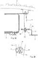
- FIG. 1A is a major component sectional view showing a carbody of a railcar according to Embodiment 1.
- FIG. 1B is an enlarged perspective view showing a part of the carbody of FIG. 1A when viewed from below.
- FIG. 2A is a major component sectional view for explaining assembling of the carbody shown in FIG. 1 .
- FIG. 2B is an enlarged perspective view showing a part of the carbody of FIG. 2A when viewed from below.
- FIG. 3A is a major component sectional view for explaining assembling of the carbody shown in FIG. 1 .
- FIG. 3B is an enlarged perspective view showing a part of the carbody of FIG. 3A when viewed from below.
- FIG. 4A is a major component sectional view for explaining assembling of the carbody shown in FIG. 1 .
- FIG. 4B is an enlarged perspective view showing a part of the carbody of FIG. 4A when viewed from below.
- FIG. 5 is a major component sectional view showing the carbody of the railcar according to Embodiment 2.
- FIG. 6 is a plan view showing a part of the carbody shown in FIG. 5 .
- FIG. 7 is a major component sectional view showing the carbody of the railcar according to Embodiment 3.
- FIG. 1A is a major component sectional view showing a carbody 1 of a railcar according to Embodiment 1.
- FIG. 1B is an enlarged perspective view showing a part of the carbody 1 of FIG. 1A when viewed from below.
- the carbody 1 of the railcar of the present embodiment includes a roof bodyshell 2 .
- the roof bodyshell 2 includes a circular-arc corrugated plate 3 and a plurality of carlines 4 .
- the corrugated plate 3 is convex upward when viewed from a railcar longitudinal direction (hereinafter may also be referred to as a rail direction or a forward/rearward direction).
- the plurality of carlines 4 are fixed to a lower surface of the corrugated plate 3 , extends in a railcar width direction (hereinafter may also be referred to as a sleeper direction or a crosswise direction), and are arranged at intervals in the railcar longitudinal direction.
- a first reinforcing member 5 extending in the railcar longitudinal direction is fixed to lower surfaces of the carlines 4 .
- the first reinforcing member 5 includes: a horizontal bottom wall portion 5 a ; a pair of side wall portions 5 b projecting upward from both respective railcar width direction ends of the bottom wall portion 5 a ; and flange portions 5 c projecting from respective upper ends of the side wall portions 5 b in directions away from each other.
- Circular holes each having a complete round shape are formed at the bottom wall portion 5 a of the first reinforcing member 5 at intervals in the railcar longitudinal direction. Nuts communicating with the respective circular holes are welded to an upper surface of the bottom wall portion 5 a . It should be noted that internal threads may be formed on inner peripheral surfaces of the circular holes.
- Supporting rods 10 (supporting bodies) provided under the roof bodyshell 2 are fixed to the first reinforcing member 5 .
- Each of the supporting rods 10 has an axis extending in a vertical direction. Specifically, a below-described upper end portion 10 b of the supporting rod 10 is threadedly engaged with the circular hole of the first reinforcing member 5 .
- a second reinforcing member 6 having a frame plate shape is sandwiched between the supporting rod 10 and the first reinforcing member 5 . To be specific, the first reinforcing member 5 and the second reinforcing member 6 are fastened together by the supporting rod 10 .
- An air conditioning duct 7 located at a middle in the railcar width direction is fixed to the second reinforcing member 6 .
- a ventilation hole 7 aa is formed at a railcar width direction end portion of a lower wall portion 7 a of the air conditioning duct 7 .
- a guide member 8 configured to guide wind flowing out from the ventilation hole 7 a is attached to the lower wall portion 7 a of the air conditioning duct 7 .
- a middle ceiling plate 9 is attached to a middle portion of a lower surface of the lower wall portion 7 a of the air conditioning duct 7 , the middle portion being not covered with the guide member 8 .
- a space under the middle ceiling plate 9 is a passenger room where passengers stay.
- the supporting rod 10 includes: a columnar rod main body portion 10 a ; the upper end portion 10 b provided at an upper side of the rod main body portion 10 a ; and a lower end portion 10 c provided at a lower side of the rod main body portion 10 a .
- the upper end portion 10 b is an upper external thread portion that is smaller in diameter than the rod main body portion 10 a and projects upward from the rod main body portion 10 a .
- the lower end portion 10 c is a lower external thread portion that is smaller in diameter than the rod main body portion 10 a and projects downward from the rod main body portion 10 a .
- the upper end portion 10 b of the supporting rod 10 is threadedly engaged with the bottom wall portion 5 a of the first reinforcing member 5 .
- the supporting rod 10 is attached to the roof bodyshell 2 so as to be positioned in the vertical direction and a horizontal direction.
- a rotating body 11 having a circular plate shape is threadedly engaged with the lower end portion 10 c of the supporting rod 10 so as to be rotatable.
- a middle internal thread hole 11 a (see FIG. 2B ) having an axis extending in the vertical direction is formed at a center of the rotating body 11 , and the middle internal thread hole 11 a is threadedly engaged with the lower end portion 10 c .
- the rotating body 11 by rotating the rotating body 11 relative to the supporting rod 10 about the axis extending in the vertical direction, the rotating body 11 is displaced relative to the supporting rod 10 in the vertical direction.
- Roughness for example, knurling
- a side ceiling plate bracket 13 (support target member) fixed to a side ceiling plate 12 is attached to the rotating body 11 .
- the side ceiling plate bracket 13 is supported by the roof bodyshell 2 through the supporting rod 10 and the rotating body 11 .
- the side ceiling plate 12 is located away from the middle ceiling plate 9 and the guide member 8 outward in the railcar width direction and is arranged outside the supporting rod 10 in the railcar width direction and under the supporting rod 10 . It is desirable that a vertical position (height position) of a lower surface of the side ceiling plate 12 coincide with a vertical position (height position) of a lower surface of the middle ceiling plate 9 .
- the vertical position of the lower surface of the side ceiling plate 12 and the vertical position of the lower surface of the middle ceiling plate 9 need to be adjusted to reduce a displacement length L between the vertical position of the lower surface of the side ceiling plate 12 and the vertical position of the lower surface of the middle ceiling plate 9 .
- the side ceiling plate bracket 13 includes: a horizontal upper wall portion 13 a ; a side wall portion 13 b hanging down from a railcar width direction outer end portion of the upper wall portion 13 a ; and a horizontal lower wall portion 13 c projecting from a lower end portion of the side wall portion 13 b outward in the railcar width direction.
- the lower wall portion 13 c of the side ceiling plate bracket 13 is fixed to the side ceiling plate 12 .
- the upper wall portion 13 a of the side ceiling plate bracket 13 is fixed to the rotating body 11 from below. Specifically, by fastening nuts N 1 and N 2 to the lower end portion 10 c of the supporting rod 10 from under the upper wall portion 13 a , the side ceiling plate bracket 13 is fixed to the rotating body 11 (see FIGS.
- the side ceiling plate bracket 13 is attached to the rotating body 11 so as to be positioned in the vertical direction.
- the rotating body 11 is provided such that when viewed from below, a part of the rotating body 11 protrudes from an end edge of the side ceiling plate bracket 13 in the horizontal direction. With this, a worker can rotate the rotating body 11 by hand from below, the rotating body 11 being located at an upper side of the side ceiling plate bracket 13 .
- a grab rail bracket 16 (support target member) supporting a grab rail 15 to which a hanging strap 14 (strap) is attached is attached to the rotating body 11 (see FIGS. 4A and 4B ).
- the grab rail bracket 16 is supported by the roof bodyshell 2 through the rotating body 11 and the supporting rod 10 .
- the grab rail bracket 16 includes: a plurality of attaching portions 16 b attached to the rotating body 11 ; a main body portion 16 c extending downward from the attaching portions 16 b ; a hook portion 16 d formed at a lower end portion of the main body portion 16 c , the grab rail 15 being placed on the hook portion 16 d from above; and a fixing portion 16 e projecting from an intermediate portion of the main body portion 16 c in the horizontal direction, a lighting base plate 17 being fixed to the fixing portion 16 e.
- Attachment holes 16 a that are elongated holes each having a long axis extending in the railcar longitudinal direction are formed at the respective attaching portions 16 b of the grab rail bracket 16 .
- the plurality of (in the present embodiment, four) attaching portions 16 b of the grab rail bracket 16 are connected to a region of the lower surface of the rotating body 11 , the region being located around the axis of the supporting rod 10 .
- the attachment holes 16 a of the plurality of attaching portions 16 b are arranged at intervals on a virtual circle around the axis of the supporting rod 10 .
- a plurality of attachment holes 11 b (see FIG.
- each having an axis extending in the vertical direction are formed at the rotating body 11 .
- the plurality of attachment holes 11 b are arranged outside the middle internal thread hole 11 a in a radial direction at intervals in a circumferential direction.
- Each of the attachment holes 11 b is smaller in diameter than the middle internal thread hole 11 a .
- the plurality of attachment holes 11 b are arranged at regular intervals on a virtual circle around the axis of the supporting rod 10 .
- Internal threads are formed on inner peripheral surfaces of the attachment holes 11 b of the rotating body 11 . It should be noted that instead of forming the internal threads on the attachment holes 11 b , nuts communicating with the respective attachment holes 11 b may be fixed to an upper surface of the rotating body 11 .
- the attachment holes 11 b are eight attachment holes arranged on the virtual circle such that the adjacent attachment holes are spaced apart from each other by 45°.
- the rotating body 11 is adjustable in the vertical direction by rotating the rotating body 11 relative to the supporting rod 10 . Therefore, the height of the grab rail bracket 16 can be adjusted with a higher degree of accuracy.
- Adjustment holes 13 aa , 13 ab , and 13 ac are formed at the upper wall portion 13 a of the side ceiling plate bracket 13 .
- the attachment hole 16 a , the adjustment hole 13 ab , and the attachment hole 11 b communicate with one another, and a fastening member B 1 (for example, a bolt) is fastened to the attachment hole 11 b through the attachment hole 16 a and the adjustment hole 13 ab .
- the grab rail bracket 16 and the side ceiling plate bracket 13 are fastened together by the fastening member B 1 . With this, the grab rail bracket 16 is attached to the rotating body 11 so as to be positioned in the vertical direction.
- a lighting device 18 (for example, a fluorescent light) is attached to the lighting base plate 17 .
- the lighting base plate 17 is arranged so as to close a gap between the guide member 8 and the side ceiling plate 12 from below. Specifically, when viewed from below, the lighting base plate 17 overlaps an end portion of the guide member 8 , the end portion being adjacent to a railcar width direction middle side of the lighting base plate 17 , and also overlaps an end portion of the side ceiling plate 12 , the end portion being adjacent to a railcar width direction outer side of the lighting base plate 17 .
- a plurality of lighting base plates 17 are lined up in the railcar longitudinal direction, and each of the grab rail brackets 16 projects downward toward the passenger room from a boundary between the lighting base plates 17 adjacent to each other in the railcar longitudinal direction.
- FIGS. 2 to 4 are diagrams for explaining assembling of the carbody 1 shown in FIG. 1 .
- a first adjustment hole 13 aa As shown in FIGS. 2A and 2B , a first adjustment hole 13 aa , second adjustment holes 13 ab , and a third adjustment hole 13 ac are formed at the upper wall portion 13 a of the side ceiling plate bracket 13 .
- the lower end portion 10 c of the supporting rod 10 is inserted through the first adjustment hole 13 aa .
- a diameter of the first adjustment hole 13 aa is larger than an outer diameter of the lower end portion 10 c of the supporting rod 10 .
- a plurality of second adjustment holes 13 ab are arranged outside the first adjustment hole 13 aa in the radial direction at intervals in the circumferential direction.
- Each of the second adjustment holes 13 ab is larger than the attachment hole 11 b of the rotating body 11 .
- the plurality of second adjustment holes 13 ab are arranged at regular intervals on a virtual circle around the axis of the supporting rod 10 .
- a temporary fastening member B 2 (for example, a bolt) is inserted through the third adjustment hole 13 ac .
- the third adjustment hole 13 ac is formed at such a position as to communicate with a temporary fastening hole 11 c of the rotating body 11 , the position being located in a region outside the first adjustment hole 13 aa in the radial direction.
- the lower end portion 10 c of the supporting rod 10 is inserted through the first adjustment hole 13 aa of the upper wall portion 13 a of the ceiling plate bracket 13 , and the upper wall portion 13 a is brought into contact with the lower surface of the rotating body 11 . Then, the vertical position of the rotating body 11 is adjusted so as to reduce the displacement between the vertical position of the lower surface of the side ceiling plate 12 and the vertical position of the lower surface of the middle ceiling plate 9 . Specifically, by rotating the rotating body 11 relative to the supporting rod 10 by hand of a worker, the rotating body 11 is displaced relative to the supporting rod 10 in the vertical direction.
- the nut N 1 is threadedly engaged with the lower end portion 10 c of the supporting rod 10 , and with this, the upper wall portion 13 a of the side ceiling plate bracket 13 is sandwiched between the rotating body 11 and the nut N 1 .
- the side ceiling plate bracket 13 is attached to the rotating body 11 so as to be positioned in the vertical direction.
- the temporary fastening member B 2 is fastened to the temporary fastening hole 11 c of the rotating body 11 through the third adjustment hole 13 ac , and with this, the side ceiling plate bracket 13 is positioned relative to the rotating body 11 in the horizontal direction so as not to move relative to the rotating body 11 .
- the fastening member B 1 is fastened to the attachment hole 11 b through the attachment hole 16 a and the second adjustment hole 13 ab .
- the grab rail bracket 16 is fastened to the rotating body 11 together with the side ceiling plate bracket 13 by the fastening member B 1 .
- a plurality of fastening members B 1 are arranged at regular intervals on a virtual circle around the axis of the supporting rod 10 .
- the lighting base plate 17 is attached to the fixing portion 16 e of the grab rail bracket 16 .
- the grab rail 15 is supported by the hook portion 16 d of the grab rail bracket 16 .
- the rotating body 11 is threadedly engaged with the supporting rod 10 . Only by rotating the rotating body 11 relative to the supporting rod 10 , the rotating body 11 can be displaced relative to the supporting rod 10 in the vertical direction. Therefore, the vertical distance from the support target member (the side ceiling plate bracket 13 , the grab rail bracket 16 , or the like) to the roof bodyshell 2 can be adjusted by such simple work. As long as the rotating body 11 is not rotated relative to the supporting rod 10 , relative positions of the supporting rod 10 and the rotating body 11 in the vertical direction do not change. Therefore, the vertical distance between the roof bodyshell 2 and the support target member can be stably determined. Further, since the rotating body 11 is configured to be threadedly engaged with the supporting rod 10 so as to rotate relative to the supporting rod 10 around the axis extending in the vertical direction, strength with respect to load acting in the vertical direction is satisfactory.
- the support target members (the side ceiling plate bracket 13 , the grab rail bracket 16 , and the like) are fastened by the plurality of fastening members B 1 to a region of the lower surface of the rotating body 11 , the region being located around the axis of the supporting rod 10 . Therefore, even when load in the vertical direction is applied to the support target member, the supporting rod 10 can stably receive the load along the axis. Thus, load resistance improves.
- the first to third adjustment holes 13 aa , 13 ab , and 13 ac are formed at the side ceiling plate bracket 13 and are larger than the lower end portion 10 c of the supporting rod 10 , and the attachment hole 11 b and temporary fastening hole 11 c of the rotating body 11 .
- FIG. 5 is a major component sectional view showing a carbody 101 of the railcar according to Embodiment 2.
- FIG. 6 is a plan view showing major components of the carbody 101 shown in FIG. 5 .
- a receiving tray member 120 is fixed to the roof bodyshell 2 .
- the receiving tray member 120 includes: a recess 120 a that is open upward; and a flange portion 120 b horizontally projecting from an upper end edge of the recess 120 a .
- the recess 120 a is rectangular in plan view.
- a rectangular nut N 3 (rotating body) is accommodated in the recess 120 a .
- the nut N 3 has such a size as to interfere with side surfaces of the recess 120 a and therefore be not rotatable by a predetermined angle or more.
- a hole 120 aa that is smaller than the nut N 3 is formed at a bottom wall portion of the recess 120 a , so that the nut N 3 does not fall off.
- a supporting rod 110 having an axis extending in the vertical direction is inserted through the hole 120 aa of the receiving tray member 120 .
- the supporting rod 110 includes: a columnar rod main body portion 110 a ; an upper end portion 110 b provided at an upper side of the rod main body portion 110 a ; a lower end portion 110 c provided at a lower side of the rod main body portion 110 a ; and a flange portion 110 d projecting from the main body portion 110 a outward in the radial direction.
- the upper end portion 110 b is an upper external thread portion that is smaller in diameter than the rod main body portion 110 a and projects upward from the rod main body portion 110 a .
- the lower end portion 110 c is a lower external thread portion that is smaller in diameter than the rod main body portion 110 a and projects downward from the rod main body portion 110 a.
- a nut N 4 is threadedly engaged with an intermediate portion of the upper end portion 110 b of the supporting rod 110 .
- a part of the upper end portion 110 b of the supporting rod 110 which part is located higher the nut N 4 (rotating body) is inserted upward through the hole 120 aa of the receiving tray member 120 to be fastened by the nut N 3 from above.
- a cover 125 is attached to the receiving tray member 120 so as to cover the upper end portion 110 b of the supporting rod 110 from above with a gap between the cover 125 and the upper end portion 110 b . Since the upper end portion 110 b of the supporting rod 110 is smaller in diameter than the hole 120 aa , the position of the supporting rod 110 is adjustable in the horizontal direction.
- the nuts N 3 and N 4 and the supporting rod 110 are positioned relative to the receiving tray member 120 in the horizontal direction.
- the nuts N 3 and N 4 (rotating bodies) and the supporting rod 110 are positioned relative to the roof bodyshell 2 in the vertical direction and the horizontal direction.
- the supporting rod 110 By rotating the supporting rod 110 relative to the nuts N 3 and N 4 , the supporting rod 110 is displaced relative to the receiving tray member 120 in the vertical direction.
- the flange portion 110 d of the supporting rod 110 can be displaced relative to the roof bodyshell 2 in the vertical direction.
- a ceiling plate 111 (support target member) is fixed to the flange portion 110 d of the supporting rod 110 . Therefore, by rotating the supporting rod 110 relative to the nuts N 3 and N 4 , the vertical distance between the roof bodyshell 2 and the ceiling plate 111 can be adjusted.
- An adapter 121 (rotating body) is threadedly engaged with the lower end portion 110 c of the supporting rod 110 .
- the adapter 121 has a columnar shape extending in the vertical direction.
- a recess 121 a is formed on an upper end surface of the adapter 121 , and internal threads are formed on an inner peripheral surface of the recess 121 a .
- the lower end portion 110 c of the supporting rod 110 is threadedly engaged with the recess 121 a .
- a pin hole 121 b is formed at the adapter 121 so as to penetrate the adapter 121 in the horizontal direction.
- a pipe 122 (support target member) is fitted to the adapter 121 from below.
- the pipe 122 is, for example, a bracket portion of the grab rail to which the hanging strap is attached.
- a pin hole 122 a is formed at the pipe 122 so as to penetrate the pipe 122 in the horizontal direction.
- a pin 123 is inserted through the pin hole 122 a of the pipe 122 and the pin hole 121 b of the adapter 121 .
- the pin 123 includes: a shaft portion 123 a on which threads are not formed; a head portion 123 b formed at one end portion of the shaft portion 123 a ; and a through hole 123 c formed at the other end portion of the shaft portion 123 a and extending in a direction perpendicular to an axial direction, a retaining pin 124 being attached to the through hole 123 c .
- the cover 125 is attached to an upper end portion of the pipe 122 so as to cover the pin 123 and the adapter 121 .
- the supporting rod 110 can be displaced relative to the roof bodyshell 2 in the vertical direction. Therefore, the vertical distance from the ceiling plate 111 to the roof bodyshell 2 can be adjusted by such simple work. Further, only by rotating the adapter 121 relative to the supporting rod 110 , the adapter 121 can be displaced relative to the ceiling plate 111 and the roof bodyshell 2 in the vertical direction. Therefore, the vertical distance from the adapter 121 to the ceiling plate 111 can be adjusted by such simple work.
- the vertical distance from the ceiling plate 111 (first support target member) to the roof bodyshell 2 and the vertical distance from the pipe 122 (second support target member) to the ceiling plate 111 (first support target member) can be individually adjusted on the same axis while using the supporting rod 110 .
- FIG. 7 is a major component sectional view showing a carbody 201 of a railcar according to Embodiment 3.
- the first reinforcing member 5 extending in the railcar longitudinal direction is fixed to the lower surface of the roof bodyshell 2
- a supporting rod 210 having an axis extending in the vertical direction is fixed to the first reinforcing member 5 .
- the supporting rod 210 includes: a columnar rod main body portion 210 a ; a flange portion 210 b projecting from an upper end of the rod main body portion 210 a in the horizontal direction; and a lower end portion 210 c provided at a lower side of the rod main body portion 210 a .
- the lower end portion 210 c is an external thread portion that is smaller in diameter than the rod main body portion 210 a and projecting downward from the rod main body portion 210 a.
- the flange portion 210 b of the supporting rod 210 is fixed to the first reinforcing member 5 by fastening members B 3 (for example, bolts).
- the first reinforcing member 5 is provided with elongated holes into which the fastening members B 3 are inserted, and the position of the supporting rod 210 is adjustable in the railcar longitudinal direction.
- An adapter 221 (rotating body) is threadedly engaged with the lower end portion 210 c of the supporting rod 210 .
- the adapter 221 has a cylindrical shape extending in the vertical direction, and internal threads are formed on upper and low inner peripheral surfaces of the adapter 221 .
- the adapter 221 includes: a cylindrical portion 221 a ; an upper screw seat portion 221 b fitted to and connected to the cylindrical portion 221 a from above, internal threads being formed on an inner peripheral surface of the upper screw seat portion 221 b ; and a lower screw seat portion 221 c fitted to and connected to the cylindrical portion 221 a from below, internal threads being formed on an inner peripheral surface of the lower screw seat portion 221 c .
- the upper screw seat portion 221 b includes: a tubular portion 221 ba fitted to the cylindrical portion 221 a from above; and a flange portion 221 bb projecting from an upper end of the tubular portion 221 ba in the horizontal direction.
- the lower screw seat portion 221 c includes: a tubular portion 221 ca fitted to the cylindrical portion 221 a from below; and a flange portion 221 cb projecting from a lower end of the tubular portion 221 ca in the horizontal direction.
- Two nuts N 5 and N 6 are threadedly engaged with the lower end portion 210 c of the supporting rod 210 , and the upper screw seat portion 221 b of the adapter 221 is threadedly engaged with a part of the lower end portion 210 c , the part being located lower than the nuts N 5 and N 6 .
- the adapter 221 By rotating the adapter 221 relative to the supporting rod 210 , the adapter 221 is displaced relative to the supporting rod 210 in the vertical direction. In a state where the vertical position of the adapter 221 is determined, the nuts N 5 and N 6 are tightened with respect to the adapter 221 .
- An external thread portion 222 a of a bracket portion 222 of the grab rail is threadedly engaged with the lower screw seat portion 221 c of the adapter 221 through a ceiling plate 211 from below.
- a ceiling plate 211 is sandwiched between the bracket portion 222 and the adapter 221 , both the bracket portion 222 and the ceiling plate 211 are attached to the adapter 221 .
- the ceiling plate 211 is provided with an elongated hole extending in the railcar width direction (sleeper direction), and the position of the bracket portion 222 in the railcar width direction is adjustable.
- the adapter 221 can be displaced relative to the roof bodyshell 2 in the vertical direction. Therefore, the vertical distance from each of the ceiling plate 211 and the bracket portion 222 to the roof bodyshell 2 can be adjusted by such simple work.
- the present invention is not limited to the above embodiments, and modifications, additions, and eliminations of components may be made within the scope of the present invention.
- the above embodiments may be combined arbitrarily. For example, a part of components or methods in one embodiment may be applied to another embodiment.
- the supporting rod may be not solid but hollow.
- the supporting rod may not have a circular cross section.
- a supporting body not having a rod shape may be used.
- other fixtures such as a rivet may be used as the fastening member.
- the support target member may be an interior display device, a baggage holder device, a stanchion pole, or the like in addition to the above.
Abstract
Description
-
- 1, 101, 201 carbody
- 2 roof bodyshell
- 10, 110, 210 supporting rod
- 11 rotating body
- 13 side ceiling plate bracket (support target member)
- 13 aa first adjustment hole
- 13 ab second adjustment hole
- 16 grab rail bracket (support target member)
- 111, 211 ceiling plate (support target member)
- 121, 221 adapter (rotating body)
- 122 pipe (support target member)
- N3, N4 nut (rotating body)
Claims (4)
Applications Claiming Priority (3)
| Application Number | Priority Date | Filing Date | Title |
|---|---|---|---|
| JP2014224948A JP6450150B2 (en) | 2014-11-05 | 2014-11-05 | Railway car body |
| JP2014-224948 | 2014-11-05 | ||
| PCT/JP2015/004956 WO2016072043A1 (en) | 2014-11-05 | 2015-09-29 | Railway vehicle body |
Publications (2)
| Publication Number | Publication Date |
|---|---|
| US20170320503A1 US20170320503A1 (en) | 2017-11-09 |
| US10597048B2 true US10597048B2 (en) | 2020-03-24 |
Family
ID=55908791
Family Applications (1)
| Application Number | Title | Priority Date | Filing Date |
|---|---|---|---|
| US15/524,831 Active 2036-07-22 US10597048B2 (en) | 2014-11-05 | 2015-09-29 | Carbody of railcar |
Country Status (4)
| Country | Link |
|---|---|
| US (1) | US10597048B2 (en) |
| JP (1) | JP6450150B2 (en) |
| CN (1) | CN107074252B (en) |
| WO (1) | WO2016072043A1 (en) |
Families Citing this family (4)
| Publication number | Priority date | Publication date | Assignee | Title |
|---|---|---|---|---|
| GB2546836B (en) * | 2016-06-24 | 2019-06-26 | Bombardier Transp Gmbh | Method of assembling a ceiling framework to a roof structure of a vehicle body of a rail vehicle |
| CN109606409B (en) * | 2019-01-30 | 2024-02-02 | 重庆中车长客轨道车辆有限公司 | Vehicle armrest mounting structure and vehicle |
| JP6994095B1 (en) * | 2020-09-16 | 2022-01-14 | 日本車輌製造株式会社 | Railroad vehicle |
| CN115123325B (en) * | 2022-07-29 | 2024-03-22 | 中车唐山机车车辆有限公司 | Top plate structure of rail vehicle and rail vehicle |
Citations (6)
| Publication number | Priority date | Publication date | Assignee | Title |
|---|---|---|---|---|
| US4570545A (en) | 1983-09-19 | 1986-02-18 | The Budd Company | Connecting means for a stanchion in a railway car |
| US5365662A (en) | 1992-07-10 | 1994-11-22 | Inventio Ag | Method for manufacturing an internal structure for integral railway coach bodies |
| CN201712615U (en) | 2010-07-27 | 2011-01-19 | 唐山轨道客车有限责任公司 | Hoisting structure |
| JP2012126185A (en) | 2010-12-14 | 2012-07-05 | Kawasaki Heavy Ind Ltd | Interior article mounting structure of railway vehicle |
| WO2012137706A1 (en) | 2011-04-05 | 2012-10-11 | 株式会社青山製作所 | Interior member mounting structure for railway car |
| CN102913520A (en) | 2012-10-31 | 2013-02-06 | 中国北车集团大连机车车辆有限公司 | Bolt adjusting assembly and railway vehicle |
Family Cites Families (3)
| Publication number | Priority date | Publication date | Assignee | Title |
|---|---|---|---|---|
| DE20315057U1 (en) * | 2003-09-26 | 2005-02-10 | Deisenroth, Ulf | Modular protection space system, in particular for the transport of persons and / or objects |
| CN101804818B (en) * | 2009-11-16 | 2011-09-21 | 唐山轨道客车有限责任公司 | Top slab connecting structure inside railway train roof |
| CN201777257U (en) * | 2010-09-14 | 2011-03-30 | 南车南京浦镇车辆有限公司 | Multi-purpose railway vehicle roof framework |
-
2014
- 2014-11-05 JP JP2014224948A patent/JP6450150B2/en active Active
-
2015
- 2015-09-29 WO PCT/JP2015/004956 patent/WO2016072043A1/en active Application Filing
- 2015-09-29 US US15/524,831 patent/US10597048B2/en active Active
- 2015-09-29 CN CN201580059643.6A patent/CN107074252B/en active Active
Patent Citations (7)
| Publication number | Priority date | Publication date | Assignee | Title |
|---|---|---|---|---|
| US4570545A (en) | 1983-09-19 | 1986-02-18 | The Budd Company | Connecting means for a stanchion in a railway car |
| US5365662A (en) | 1992-07-10 | 1994-11-22 | Inventio Ag | Method for manufacturing an internal structure for integral railway coach bodies |
| NO300203B1 (en) | 1992-07-10 | 1997-04-28 | Inventio Ag | Procedure for integrated manufacture of inner lining for bodywork and bodywork made according to the same |
| CN201712615U (en) | 2010-07-27 | 2011-01-19 | 唐山轨道客车有限责任公司 | Hoisting structure |
| JP2012126185A (en) | 2010-12-14 | 2012-07-05 | Kawasaki Heavy Ind Ltd | Interior article mounting structure of railway vehicle |
| WO2012137706A1 (en) | 2011-04-05 | 2012-10-11 | 株式会社青山製作所 | Interior member mounting structure for railway car |
| CN102913520A (en) | 2012-10-31 | 2013-02-06 | 中国北车集团大连机车车辆有限公司 | Bolt adjusting assembly and railway vehicle |
Non-Patent Citations (2)
| Title |
|---|
| Dec. 22, 2015 Search Report issued in International Patent Application No. PCT/JP2015/004956. |
| Dec. 22, 2015 Written Opinion issued in International Patent Application No. PCT/JP2015/004956. |
Also Published As
| Publication number | Publication date |
|---|---|
| US20170320503A1 (en) | 2017-11-09 |
| CN107074252A (en) | 2017-08-18 |
| WO2016072043A1 (en) | 2016-05-12 |
| CN107074252B (en) | 2019-11-29 |
| JP2016088285A (en) | 2016-05-23 |
| JP6450150B2 (en) | 2019-01-09 |
Similar Documents
| Publication | Publication Date | Title |
|---|---|---|
| US10597048B2 (en) | Carbody of railcar | |
| US11136124B2 (en) | Fastening system for fastening a component on a fuselage structure | |
| US9809325B2 (en) | Aircraft system component carrier system and mounting method | |
| US9963232B2 (en) | Aircraft floor panel with ball transfer unit | |
| US20190276153A1 (en) | Noncircular base frame tube cross-sections | |
| US9293746B2 (en) | Methods and systems for supporting a battery | |
| US20180206936A1 (en) | Bushing, support arm, and support system for a medical technical stand apparatus | |
| JP2021505788A (en) | Modular support frames for LED panels and LED walls containing such support frames | |
| US9331465B2 (en) | Aerial marker assemblies, components and related methods | |
| CN209025978U (en) | Captive nut, battery component and vehicle | |
| US9669928B2 (en) | Multipart fastening device for fastening a device to a reinforcing element and to the outer skin of a vehicle | |
| US20190031078A1 (en) | Load Bearing Rail and Tie-Down Ring Assembly | |
| JP2015093562A (en) | Fitting structure and fitting method for rolling stock interior trim | |
| CN108069333B (en) | Aero-engine spray pipe lifting device | |
| CN107834461B (en) | Cable bracket and manufacturing process | |
| US9914386B2 (en) | Load bearing rail and tie-down ring assembly | |
| CN111152806B (en) | Roof air guide sleeve, railway vehicle and roof air guide sleeve installation method | |
| US7950614B1 (en) | Medical equipment overhead mounting structure | |
| US5088675A (en) | Overhead hanger | |
| ES2879924T3 (en) | Loading beam configuration for a car body of a vehicle | |
| US20130170113A1 (en) | Bracket and electronic device | |
| CN109305318A (en) | Large aircraft organism safe is tethered at handle | |
| CN108838602B (en) | Welding tool for vehicle body framework | |
| CN219317981U (en) | Foot margin assembly | |
| CN103842249B (en) | Aircraft fuselage and the method realizing floor in this fuselage |
Legal Events
| Date | Code | Title | Description |
|---|---|---|---|
| AS | Assignment |
Owner name: KAWASAKI JUKOGYO KABUSHIKI KAISHA, JAPAN Free format text: ASSIGNMENT OF ASSIGNORS INTEREST;ASSIGNORS:KATO, EIICHI;GOTO, TSUNETOSHI;MIURA, SHINICHI;AND OTHERS;REEL/FRAME:042571/0372 Effective date: 20170511 |
|
| STPP | Information on status: patent application and granting procedure in general |
Free format text: DOCKETED NEW CASE - READY FOR EXAMINATION |
|
| STPP | Information on status: patent application and granting procedure in general |
Free format text: NON FINAL ACTION MAILED |
|
| STPP | Information on status: patent application and granting procedure in general |
Free format text: RESPONSE TO NON-FINAL OFFICE ACTION ENTERED AND FORWARDED TO EXAMINER |
|
| STPP | Information on status: patent application and granting procedure in general |
Free format text: NOTICE OF ALLOWANCE MAILED -- APPLICATION RECEIVED IN OFFICE OF PUBLICATIONS |
|
| STPP | Information on status: patent application and granting procedure in general |
Free format text: PUBLICATIONS -- ISSUE FEE PAYMENT VERIFIED |
|
| STCF | Information on status: patent grant |
Free format text: PATENTED CASE |
|
| AS | Assignment |
Owner name: KAWASAKI RAILCAR MANUFACTURING CO.,LTD., JAPAN Free format text: ASSIGNMENT OF ASSIGNORS INTEREST;ASSIGNOR:KAWASAKI JUKOGYO KABUSHIKI KAISHA;REEL/FRAME:060107/0954 Effective date: 20211001 |
|
| MAFP | Maintenance fee payment |
Free format text: PAYMENT OF MAINTENANCE FEE, 4TH YEAR, LARGE ENTITY (ORIGINAL EVENT CODE: M1551); ENTITY STATUS OF PATENT OWNER: LARGE ENTITY Year of fee payment: 4 |