US1056553A - Support for radiators and the like. - Google Patents
Support for radiators and the like. Download PDFInfo
- Publication number
- US1056553A US1056553A US71421912A US1912714219A US1056553A US 1056553 A US1056553 A US 1056553A US 71421912 A US71421912 A US 71421912A US 1912714219 A US1912714219 A US 1912714219A US 1056553 A US1056553 A US 1056553A
- Authority
- US
- United States
- Prior art keywords
- plate
- radiator
- wall
- bracket
- screw
- Prior art date
- Legal status (The legal status is an assumption and is not a legal conclusion. Google has not performed a legal analysis and makes no representation as to the accuracy of the status listed.)
- Expired - Lifetime
Links
- 230000015572 biosynthetic process Effects 0.000 description 1
- 230000000295 complement effect Effects 0.000 description 1
- 239000004020 conductor Substances 0.000 description 1
- 238000010276 construction Methods 0.000 description 1
- XLYOFNOQVPJJNP-UHFFFAOYSA-N water Substances O XLYOFNOQVPJJNP-UHFFFAOYSA-N 0.000 description 1
Images
Classifications
-
- F—MECHANICAL ENGINEERING; LIGHTING; HEATING; WEAPONS; BLASTING
- F24—HEATING; RANGES; VENTILATING
- F24D—DOMESTIC- OR SPACE-HEATING SYSTEMS, e.g. CENTRAL HEATING SYSTEMS; DOMESTIC HOT-WATER SUPPLY SYSTEMS; ELEMENTS OR COMPONENTS THEREFOR
- F24D19/00—Details
- F24D19/02—Arrangement of mountings or supports for radiators
Definitions
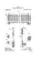
- Figure 1 shows in front elevation a wall radiator and hangers therefor, of a form provided by the invention
- Fig. 2 is a front. elevation of one of the hangers illustrated in Fig. 1
- Fig. 3 is a central vertical section of the hanger illustrated in Fig. 2;
- Figs. 4, 5 and 6 are detail sectional viewsy taken on the lines Ll--4, 5-5 and 6 6, Spectively, of Fig. 3.'
- FIG. 10 For the purpose of illustrating the invention the drawings show an improved form ot hanger adapted to be used for supporting a wall radiator.
- a radiator is represented at 10. It comprises a plurality of sections, as 11, '12. These sections are. connected end to end, and each has upper and lower horizontal tlues designated 13 and 14, respectively.
- this hanger complrises -a pla-te 17 adapted to be secured against the wall in an upright position, as by the provision of screw holes 18 and 19 'for receiving lag screws or bolts, not shown.
- the plate 17 is so disposed upon the wall, and is of such length, that its higher end is at a lower elevation than the upper edge ot' the radiator, and is there.- forc concealed when the radiator is in place.
- the bracket 20 is mounted on the wall plate 17 adjacent 963,580, dated July 5,1910.
- This means of l securing the bracket 20 in place comprises a vertically extended bolt-receiving slot 22 in the Wall plate 17, and serrations 23 formed in the front face of the Wall plate at each side of the slot.
- Complementary serrations 24. are formed upon the inner end of the bracket 20, and a bolt 25 is extended through the bracket and through vthe slot 22.
- the seat 21 is preferably provided with means for permitting longitudinal movement of the radiator on the bracket without; friction. As shown, a plurality of ball sockets 28 are formed in the seat 21,
- each socket 1s preferably made with Haring walls, as indicated at 30 and 31 (Fig. 6), and a channel 32 extends downwardly from the foot of the socket through the bracket 20.
- Openings for the escape of scale from t-he lower ends of the channels 32 are conveniently provided by forming a recess 33 in' the under side of the bracket 20, whereby the under side of the bolt 25 is exposed for a portion of its length intermediate its ends, as indicated abiti- (Fig. 3), and by the formation of grooves 35, 36, in the ⁇ bracket, about the bolt, each groove communicating with one of the channels 32 and with the re.-
- the radiator is peris permitted to find its way out of the sockets 28 through the vchannels 32 andl grooves and 36.
- a chamber 39 is formed in the plate 17 adjacent its higher end, and that part of the plate in front of the chamber is provided with a longitudinal slot extending to the end of the plate.
- the extension member 37 is of T shape in cross-section, as most clearly shown in Fig. 5, and is provided adjacent its lower end with a/bac-kwardly extending lug 41, having a screw-threaded apL erture 42.
- the narrower part of the extension 37 tits in the slot 40, while its wider portion and the lug 41 run in the chamber 39.
- a vertically arranged adjusting screw 48' is provided.
- This adjusting screw extends downwardly through an opening 44 in the higherl end of the plate 17. Its lower end enters a socket 45 formed in the bottom wall of the chamber'39.
- the screw 43 is fixed against longitudinal movement with respect to the plate 17, by having a circumferential groove 46 formed in the screw adjacent'its lower end, and by passing a pin 47 (Fig.
- the invention provides a convenient and efficient ⁇ means'forsupport-ing a wall radiaend being lower than the upper edge of the radiator, a bracket projecting outwardly from the plate adjacent its lower end and constituting a supporting seat for the radiator, a hooked member adapted for engagement with the-upper edge of the radiator and having a downwardly extending shank in telescopic sliding engagement with the higher end of the said plate, and an adjusting screw reacting between the shank of the hooked member and the plate.
- a plate adapted to be secured te the wall in an upright position and havin a vertical slideway adjacent its upper en means fixed to the plate adjacent its lower end for engaging and supporting the lower portion of the radiator, a hooked member engageable with an upper part. of the radiator having a shank ruiming in the vertical slideway of the plate, and a vertically disposed adjusting screw reacting between an end wall of the said slideway of the plate and the shank of the said hooked member.
- a hanger tor wall radiators in combination, a plate adapted to be secured to the wall in an upright position, a pair of brackets connected to the plate adjacent its opposite ends and projecting outwardly therefrom for engaging the upper and lower portions of the radiator, one of said brackets being slidingly mounted on the plate, and a vertically disposed adjust-ing screw having its head exposed at an end of the plate reacting between the plate and the slidinglyl mounted hracluit.
Landscapes
- Engineering & Computer Science (AREA)
- Physics & Mathematics (AREA)
- Thermal Sciences (AREA)
- Chemical & Material Sciences (AREA)
- Combustion & Propulsion (AREA)
- Mechanical Engineering (AREA)
- General Engineering & Computer Science (AREA)
- Holders For Apparel And Elements Relating To Apparel (AREA)
Description
A. KEHM; SUPPORT FOB RADIATORS'AND THE LIKE. 'APPLIO'ATION FILED AUG. 9, 1912. v 1 ,056,553, Patented Mar; 18, 19.13.
5'- 6 we/zrg AUGUST KEHM, or CHICAGO, ILLINOIS.
SUPPORT FOR RADIIIATORS A NID, TEHE LIKE.
Specicatign of Letters Patent.
Patented Mar. 18, 1913.
Application led August 9, 1912.` Serial No. 714,219.
4 or other conductors of hot Water or steam,
which extend in a substantially horizonal direction.
The invention is eXempliiedin the structure which is hereinafter described, and which is illustrated in the accompanying drawings, whereinp Figure 1 shows in front elevation a wall radiator and hangers therefor, of a form provided by the invention; Fig. 2 is a front. elevation of one of the hangers illustrated in Fig. 1; Fig. 3 is a central vertical section of the hanger illustrated in Fig. 2; and
Figs. 4, 5 and 6 are detail sectional viewsy taken on the lines Ll--4, 5-5 and 6 6, Spectively, of Fig. 3.'
I, For the purpose of illustrating the invention the drawings show an improved form ot hanger adapted to be used for supporting a wall radiator. Such a radiator is represented at 10. It comprises a plurality of sections, as 11, '12. These sections are. connected end to end, and each has upper and lower horizontal tlues designated 13 and 14, respectively. Two or more of the hangers, as 15, 1G,.will be used for supporting the radiator 10, but as these are preferably of like construction only one will be described. As shown` this hanger complrises -a pla-te 17 adapted to be secured against the wall in an upright position, as by the provision of screw holes 18 and 19 'for receiving lag screws or bolts, not shown. Preferably the plate 17 is so disposed upon the wall, and is of such length, that its higher end is at a lower elevation than the upper edge ot' the radiator, and is there.- forc concealed when the radiator is in place. A supportingr bracket 20, having a seat. 2l Jfor receiving the lower horizontal flue, as 14. of the corresponding radiator section,
5 is mounted on the wall plate 17 adjacent 963,580, dated July 5,1910. This means of l securing the bracket 20 in place comprises a vertically extended bolt-receiving slot 22 in the Wall plate 17, and serrations 23 formed in the front face of the Wall plate at each side of the slot. Complementary serrations 24. are formed upon the inner end of the bracket 20, and a bolt 25 is extended through the bracket and through vthe slot 22. A clamping nut 26, applied to the inner end of the bolt 25 and fitting in an elongated recess 27 formed in the back of the wall plate about the slot 22, serves for drawing the inner end of t-he bracket againstthe serrated face of the wall plate and thereby securingl it in any vertically adjusted position. The seat 21 is preferably provided with means for permitting longitudinal movement of the radiator on the bracket without; friction. As shown, a plurality of ball sockets 28 are formed in the seat 21,
and an anti-frictionball 29 tits loosely in A each of these sockets and projects upwardly therefrom for engagement with the lower edge of the radiator. To prevent the accumula-tum of scale in the sockets 28 about the ball 29, each socket 1s preferably made with Haring walls, as indicated at 30 and 31 (Fig. 6), and a channel 32 extends downwardly from the foot of the socket through the bracket 20.
Openings for the escape of scale from t-he lower ends of the channels 32 are conveniently provided by forming a recess 33 in' the under side of the bracket 20, whereby the under side of the bolt 25 is exposed for a portion of its length intermediate its ends, as indicated abiti- (Fig. 3), and by the formation of grooves 35, 36, in the` bracket, about the bolt, each groove communicating with one of the channels 32 and with the re.-
cess 33. By this means the radiator is peris permitted to find its way out of the sockets 28 through the vchannels 32 andl grooves and 36.
For engaging the upper part ofthe radia- .tor 10 to hold it in an upright position upon pass over the upper horizontal rflue 11 of the corresponding radiator section. A compact arrangement of parts is provided by having the extensions 37 telescopi'cally en'- f gage with the higher end of the plate 17.
Asshown, a chamber 39 is formed in the plate 17 adjacent its higher end, and that part of the plate in front of the chamber is provided with a longitudinal slot extending to the end of the plate. The extension member 37 is of T shape in cross-section, as most clearly shown in Fig. 5, and is provided adjacent its lower end with a/bac-kwardly extending lug 41, having a screw-threaded apL erture 42. The narrower part of the extension 37 tits in the slot 40, while its wider portion and the lug 41 run in the chamber 39. l? or adjustably moving the extension 37 to enable its hook end 3S to be clamped over the upper edge of the radiator 10, a vertically arranged adjusting screw 48' is provided. This adjusting screw extends downwardly through an opening 44 in the higherl end of the plate 17. Its lower end enters a socket 45 formed in the bottom wall of the chamber'39. The screw 43 is fixed against longitudinal movement with respect to the plate 17, by having a circumferential groove 46 formed in the screw adjacent'its lower end, and by passing a pin 47 (Fig.
4) through the plate 17in such a position as to enter the groove 4G. The adjusting screw 43 passes through and is in threaded engagement with the screw-threaded aperture 42 provided in the lug 41. By this arrangement the higher end of the screw 42% is exposed at the top of the plate 17 for turning the screw, and the extension 87 iuay thereby be moved up and down with respect to the plate 17.
The invention provides a convenient and efficient` means'forsupport-ing a wall radiaend being lower than the upper edge of the radiator, a bracket projecting outwardly from the plate adjacent its lower end and constituting a supporting seat for the radiator, a hooked member adapted for engagement with the-upper edge of the radiator and having a downwardly extending shank in telescopic sliding engagement with the higher end of the said plate, and an adjusting screw reacting between the shank of the hooked member and the plate.
2. In a hanger for wall radiators in com-v bination, a plate adapted to be secured te the wall in an upright position and havin a vertical slideway adjacent its upper en means fixed to the plate adjacent its lower end for engaging and supporting the lower portion of the radiator, a hooked member engageable with an upper part. of the radiator having a shank ruiming in the vertical slideway of the plate, and a vertically disposed adjusting screw reacting between an end wall of the said slideway of the plate and the shank of the said hooked member.
` 2i. ln a hanger tor wall radiators, in combination, a plate adapted to be secured to the wall in an upright position, a pair of brackets connected to the plate adjacent its opposite ends and projecting outwardly therefrom for engaging the upper and lower portions of the radiator, one of said brackets being slidingly mounted on the plate, and a vertically disposed adjust-ing screw having its head exposed at an end of the plate reacting between the plate and the slidinglyl mounted hracluit.
AUGU STW'KE HM.
Witnesses:
WALLACE CRAIG, (ncnnm 'I orrniw
Priority Applications (1)
| Application Number | Priority Date | Filing Date | Title |
|---|---|---|---|
| US71421912A US1056553A (en) | 1912-08-09 | 1912-08-09 | Support for radiators and the like. |
Applications Claiming Priority (1)
| Application Number | Priority Date | Filing Date | Title |
|---|---|---|---|
| US71421912A US1056553A (en) | 1912-08-09 | 1912-08-09 | Support for radiators and the like. |
Publications (1)
| Publication Number | Publication Date |
|---|---|
| US1056553A true US1056553A (en) | 1913-03-18 |
Family
ID=3124807
Family Applications (1)
| Application Number | Title | Priority Date | Filing Date |
|---|---|---|---|
| US71421912A Expired - Lifetime US1056553A (en) | 1912-08-09 | 1912-08-09 | Support for radiators and the like. |
Country Status (1)
| Country | Link |
|---|---|
| US (1) | US1056553A (en) |
Cited By (2)
| Publication number | Priority date | Publication date | Assignee | Title |
|---|---|---|---|---|
| US4862953A (en) * | 1988-04-29 | 1989-09-05 | Modine Manufacturing Company | Heat exchanger mounting bracket |
| US7506851B1 (en) * | 2007-02-02 | 2009-03-24 | Nigel Tooze | Radiator mounting system |
-
1912
- 1912-08-09 US US71421912A patent/US1056553A/en not_active Expired - Lifetime
Cited By (2)
| Publication number | Priority date | Publication date | Assignee | Title |
|---|---|---|---|---|
| US4862953A (en) * | 1988-04-29 | 1989-09-05 | Modine Manufacturing Company | Heat exchanger mounting bracket |
| US7506851B1 (en) * | 2007-02-02 | 2009-03-24 | Nigel Tooze | Radiator mounting system |
Similar Documents
| Publication | Publication Date | Title |
|---|---|---|
| US3387866A (en) | Luminaire | |
| US2195540A (en) | Wall hanger for radiators | |
| US2578993A (en) | Wall bracket for radiators | |
| US1884497A (en) | Combined desk and seat | |
| US1887031A (en) | Radiator supporting hanger | |
| US971077A (en) | Pipe-hanger. | |
| US853092A (en) | Shield for heating-coils. | |
| US2071337A (en) | Seat attachment for water closets | |
| US551016A (en) | Saddle-clip for bicycles | |
| US1869281A (en) | Curtain rod holder | |
| US1794949A (en) | Radiator support | |
| US1407263A (en) | Radiator hanger | |
| US1883591A (en) | Radiator hanger | |
| US392588A (en) | Foot-rest for radiators | |
| US1574353A (en) | Radiator support | |
| US509222A (en) | Clamp-joint | |
| US1547159A (en) | Radiator hanger | |
| US1569050A (en) | Radiator hanger | |
| US1393874A (en) | Radiator-bracket | |
| US1251898A (en) | Radiator. | |
| US1184435A (en) | Radiator-bracket. | |
| US727969A (en) | Radiator-support. | |
| US758545A (en) | Sink-bracket. | |
| US443175A (en) | Curtain-pole support | |
| US950517A (en) | Rack or hanger for pipes, poles, rods, and other objects. |