US10562047B2 - Coating agent valve - Google Patents
Coating agent valve Download PDFInfo
- Publication number
- US10562047B2 US10562047B2 US15/738,587 US201615738587A US10562047B2 US 10562047 B2 US10562047 B2 US 10562047B2 US 201615738587 A US201615738587 A US 201615738587A US 10562047 B2 US10562047 B2 US 10562047B2
- Authority
- US
- United States
- Prior art keywords
- coating agent
- valve element
- duct
- flushing
- inlet
- Prior art date
- Legal status (The legal status is an assumption and is not a legal conclusion. Google has not performed a legal analysis and makes no representation as to the accuracy of the status listed.)
- Active, expires
Links
Images


Classifications
-
- B—PERFORMING OPERATIONS; TRANSPORTING
- B05—SPRAYING OR ATOMISING IN GENERAL; APPLYING FLUENT MATERIALS TO SURFACES, IN GENERAL
- B05B—SPRAYING APPARATUS; ATOMISING APPARATUS; NOZZLES
- B05B1/00—Nozzles, spray heads or other outlets, with or without auxiliary devices such as valves, heating means
- B05B1/30—Nozzles, spray heads or other outlets, with or without auxiliary devices such as valves, heating means designed to control volume of flow, e.g. with adjustable passages
- B05B1/3093—Recirculation valves, i.e. the valve element opens a passage to the nozzle and simultaneously closes at least partially a return passage the feeding means
-
- B—PERFORMING OPERATIONS; TRANSPORTING
- B05—SPRAYING OR ATOMISING IN GENERAL; APPLYING FLUENT MATERIALS TO SURFACES, IN GENERAL
- B05B—SPRAYING APPARATUS; ATOMISING APPARATUS; NOZZLES
- B05B1/00—Nozzles, spray heads or other outlets, with or without auxiliary devices such as valves, heating means
- B05B1/30—Nozzles, spray heads or other outlets, with or without auxiliary devices such as valves, heating means designed to control volume of flow, e.g. with adjustable passages
- B05B1/3026—Nozzles, spray heads or other outlets, with or without auxiliary devices such as valves, heating means designed to control volume of flow, e.g. with adjustable passages the controlling element being a gate valve, a sliding valve or a cock
-
- B—PERFORMING OPERATIONS; TRANSPORTING
- B05—SPRAYING OR ATOMISING IN GENERAL; APPLYING FLUENT MATERIALS TO SURFACES, IN GENERAL
- B05B—SPRAYING APPARATUS; ATOMISING APPARATUS; NOZZLES
- B05B12/00—Arrangements for controlling delivery; Arrangements for controlling the spray area
- B05B12/14—Arrangements for controlling delivery; Arrangements for controlling the spray area for supplying a selected one of a plurality of liquids or other fluent materials or several in selected proportions to a spray apparatus, e.g. to a single spray outlet
- B05B12/1409—Arrangements for controlling delivery; Arrangements for controlling the spray area for supplying a selected one of a plurality of liquids or other fluent materials or several in selected proportions to a spray apparatus, e.g. to a single spray outlet the selection means being part of the discharge apparatus, e.g. part of the spray gun
-
- F—MECHANICAL ENGINEERING; LIGHTING; HEATING; WEAPONS; BLASTING
- F16—ENGINEERING ELEMENTS AND UNITS; GENERAL MEASURES FOR PRODUCING AND MAINTAINING EFFECTIVE FUNCTIONING OF MACHINES OR INSTALLATIONS; THERMAL INSULATION IN GENERAL
- F16K—VALVES; TAPS; COCKS; ACTUATING-FLOATS; DEVICES FOR VENTING OR AERATING
- F16K11/00—Multiple-way valves, e.g. mixing valves; Pipe fittings incorporating such valves
- F16K11/02—Multiple-way valves, e.g. mixing valves; Pipe fittings incorporating such valves with all movable sealing faces moving as one unit
- F16K11/06—Multiple-way valves, e.g. mixing valves; Pipe fittings incorporating such valves with all movable sealing faces moving as one unit comprising only sliding valves, i.e. sliding closure elements
- F16K11/072—Multiple-way valves, e.g. mixing valves; Pipe fittings incorporating such valves with all movable sealing faces moving as one unit comprising only sliding valves, i.e. sliding closure elements with pivoted closure members
- F16K11/074—Multiple-way valves, e.g. mixing valves; Pipe fittings incorporating such valves with all movable sealing faces moving as one unit comprising only sliding valves, i.e. sliding closure elements with pivoted closure members with flat sealing faces
-
- B—PERFORMING OPERATIONS; TRANSPORTING
- B05—SPRAYING OR ATOMISING IN GENERAL; APPLYING FLUENT MATERIALS TO SURFACES, IN GENERAL
- B05B—SPRAYING APPARATUS; ATOMISING APPARATUS; NOZZLES
- B05B12/00—Arrangements for controlling delivery; Arrangements for controlling the spray area
- B05B12/14—Arrangements for controlling delivery; Arrangements for controlling the spray area for supplying a selected one of a plurality of liquids or other fluent materials or several in selected proportions to a spray apparatus, e.g. to a single spray outlet
- B05B12/149—Arrangements for controlling delivery; Arrangements for controlling the spray area for supplying a selected one of a plurality of liquids or other fluent materials or several in selected proportions to a spray apparatus, e.g. to a single spray outlet characterised by colour change manifolds or valves therefor
-
- B—PERFORMING OPERATIONS; TRANSPORTING
- B05—SPRAYING OR ATOMISING IN GENERAL; APPLYING FLUENT MATERIALS TO SURFACES, IN GENERAL
- B05B—SPRAYING APPARATUS; ATOMISING APPARATUS; NOZZLES
- B05B7/00—Spraying apparatus for discharge of liquids or other fluent materials from two or more sources, e.g. of liquid and air, of powder and gas
- B05B7/14—Spraying apparatus for discharge of liquids or other fluent materials from two or more sources, e.g. of liquid and air, of powder and gas designed for spraying particulate materials
- B05B7/1404—Arrangements for supplying particulate material
Definitions
- the disclosure relates to a coating agent valve for controlling a stream of a coating agent in an application device, in particular in an atomiser (e.g. rotary atomiser).
- an atomiser e.g. rotary atomiser
- rotary atomisers are usually used as application devices.
- rotary atomisers as a rule have a main needle valve which contains a slidable valve needle which is usually driven pneumatically as valve element.
- FIG. 1A is a schematic perspective view of a coating agent valve according to the disclosure in a first rotary position for painting with a first paint and for flushing or reloading a second paint,
- FIG. 1B is a view in cross-section through the coating agent valve in the rotary position of FIG. 1A ,
- FIG. 1C is a schematic representation of the pneumatic valve drive in the rotary position according to FIGS. 1A and 1B ,
- FIG. 2A shows the coating agent valve according to FIGS. 1A-1C in a second rotary position for flushing and reloading the second paint
- FIG. 2B shows the view in cross-section according to FIG. 1B in the second rotary position
- FIG. 2C shows the representation according to FIG. 1C in the second rotary position
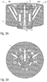
- FIGS. 3A-3C are corresponding representations in a third rotary position for flushing the paint nozzle and bell cup
- FIGS. 4A-4C are corresponding representations in a fourth rotary position for flushing or reloading the first paint
- FIGS. 5A-5C are corresponding representations in a fifth rotary position for flushing or reloading the first paint and for painting with the second paint
- FIG. 6 shows a table clarifying the technical function of the various rotary positions
- FIG. 7 is a simplified, schematic representation of a rotary atomiser according to the disclosure having a coating agent valve according to the disclosure.
- the coating agent valve according to the disclosure first of all, in line with the known main needle valves, has an adjustable valve element which controls the stream of coating agent dependent on the position of the valve element.
- the valve element in this case is however not slidable, or at least not only slidable but rotatable. This is advantageous because thereby upon a closing operation of the coating agent valve the troublesome spattering or dripping of coating agent described above does not occur.
- a further advantage of such a rotatable arrangement consists in that the coating agent valve can be realised in a small space and does not require a long main needle.
- the coating agent valve has two coating agent inlets in order to be able to supply two different coating agents.
- the coating agent valve may have a coating agent outlet in order to dispense either the first coating agent or the second coating agent.
- the rotatable valve element in this case therefore, dependent on its rotary position, selects either the first coating agent or the second coating agent, and guides it to the common coating agent outlet.
- the rotatable valve element therefore connects the coating agent outlet either to the first coating agent inlet or to the second coating agent inlet, dependent on its rotary position.
- the coating agent valve according to the disclosure permits not only control (ON/OFF) of the stream of coating agent, but also the selection of one of several coating agents, so that the coating agent valve according to the disclosure also fulfils the function of a paint changer.
- the coating agent valve has precisely two coating agent inlets in order to be able to supply two different coating agents.
- the coating agent valve according to the disclosure having more than two coating agent inlets, for example three or four coating agent inlets, in order to be able to select from among a correspondingly larger number of different paints.
- the coating agent valve preferably has a first return means and a second return means, the two return means being associated with the two coating agent inlets and permitting returning of the respective coating agent.
- a correspondingly larger number of return means can also be provided, so that one return means in each case is also associated with each coating agent inlet.
- the rotatable valve element either connects the first return means to the first coating agent inlet or blocks off the first return means dependent on its rotary position.
- the rotatable valve element either connects the second return means to the second coating agent inlet or blocks off the second return means dependent on its rotary position.
- the coating agent valve according to the disclosure therefore permits circulation of material through the coating agent valve, the circulation of material into the respective return means being able to be either enabled or blocked off by the rotatable valve element.
- the coating agent valve additionally has a flushing agent inlet via which a flushing agent can be supplied, with the rotatable valve element either blocking off the flushing agent inlet or connecting it to the coating agent outlet and the duct for externally flushing the bell cup.
- the rotatable valve is then turned such that the flushing agent inlet is blocked off, since then no flushing agent is required.
- the rotatable valve element is then turned such that the flushing agent inlet is connected to the coating agent outlet, so that the flushing agent waiting on the input side is dispensed via the coating agent outlet, in order for example to flush a paint nozzle and/or a bell cup of a rotary atomiser, as will be described in detail later.
- the rotatable valve element can be turned into different rotary positions which have different functions.
- the coating agent valve according to the disclosure can fulfil the following functions in the following rotary positions:
- the rotatable valve element In the above-mentioned first rotary position (painting with paint 1 and simultaneously flushing and reloading of paint 2 ) of the rotatable valve element, the rotatable valve element then connects the first coating agent inlet to the coating agent outlet, in order to apply the first coating agent (paint 1 ).
- the first return means is then however blocked off by the rotatable valve element, since upon application of the first paint no material circulation of the first paint is required.
- the rotatable valve element in this rotary position connects the second coating agent inlet to the second return means, in order to be able to reload the second coating agent (paint 2 ).
- the rotatable valve element in this rotary position blocks off the flushing agent inlet, since no flushing operation is to take place.
- the rotatable valve element In the above-mentioned second rotary position (only flushing and reloading with paint 2 ), the rotatable valve element on the other hand blocks off the first coating agent inlet and the first return means. On the other hand, the rotatable valve element in this rotary position connects the second coating agent inlet to the second return means in order to reload the second coating agent. Finally, the rotatable valve element in this rotary position also blocks off the flushing agent inlet since no flushing agent is required.
- both coating agent inlets and both return means are blocked off, whereas the flushing agent inlet is connected to the coating agent outlet, in order to deliver flushing agent on the output side, for example for flushing a paint nozzle and/or a bell cup of a rotary atomiser.
- valve element In the above-mentioned fourth rotary position (only flushing and reloading of paint 1 ) of the rotatable valve element, the valve element on the other hand connects the first coating agent inlet to the first return means, in order to be able to reload the first coating agent.
- the second coating agent inlet, the second return means and the flushing agent inlet on the other hand are blocked off in this rotary position.
- the valve element In the above-mentioned fifth rotary position (flushing and reloading of paint 1 and simultaneously painting with paint 2 ) of the rotatable valve element, the valve element on the other hand connects the first coating inlet to the first return means, in order to be able to reload the first coating agent.
- the second coating agent inlet on the other hand in this rotary position is connected to the coating outlet, in order to be able to apply the second coating agent.
- the second return means and the flushing agent inlet on the other hand are blocked off.
- the rotatable valve element is preferably shaped substantially cylindrically and is arranged rotatably in a hollow-cylindrical paint tube.
- the external diameter of the rotatable valve element in this case preferably corresponds to the internal diameter of the hollow-cylindrical paint tube.
- the first coating agent inlet may feed a first coating agent duct which runs in the wall of the paint tube.
- the first return means on the other hand is preferably fed from a second coating agent duct which runs in the wall of the paint tube.
- the second coating agent inlet on the other hand may feed a third coating agent duct, which likewise runs in the wall of the paint tube.
- the second return means may be fed through a fourth coating agent duct which runs in the wall of the paint tube.
- a fifth coating agent duct which is connected on the input side to the flushing agent inlet, may run in the wall of the paint tube.
- the coating agent outlet may be arranged in the rotatable valve element, in particular centrally.
- the coating agent ducts for supplying and returning the individual coating agents preferably open into the inner wall of the hollow paint tube.
- the coating agent duct and the return means for the first coating agent may open into the inner wall of the paint tube at the same angle at circumference, but axially offset relative to one another.
- the coating agent ducts for supplying and returning the second coating agent duct may also open into the inner wall of the paint tube at the same angle at circumference, but axially offset relative to one another.
- the orifice openings for the coating agent ducts (return or supply) of the various coating agents in this case are preferably arranged offset over the periphery.
- a branch bore which starts from the outer casing surface of the valve element and opens into the common coating agent outlet.
- the branch bore in this case is arranged in the valve element such that its orifice opening in the casing surface of the rotatable valve element coincides either with the orifice opening of the coating agent duct for the first coating agent or with the orifice opening of the coating agent duct for the second coating agent in the inner wall of the hollow paint tube.
- the branch bore can therefore be connected with one of the paint feed lines as desired dependent on the rotary position of the rotatable valve element.
- the orifice openings of the coating agent ducts for supplying and returning paint are arranged preferably axially offset relative to one another in the inner wall of the paint tube.
- the casing surface of the rotatable valve element there may be one recess in each case which extends in the axial direction and permits connection of the axially offset orifice openings in the inner wall of the hollow paint tube.
- circulation of material through the coating agent valve can be enabled in that the rotatable valve element is turned such that the recess lies in the inner wall of the paint tube in the region of the two axially offset orifice openings. The respective paint can then flow into the recess and flow back out of the recess again into the associated return means.
- the rotatable valve element can be turned such that the flushing agent inlet is connected to the coating agent outlet, so that flushing agent is dispensed at the exit, in order to flush for example a paint nozzle or a bell cup.
- the rotatable valve element preferably has a separate flushing agent outlet in order to deliver flushing agent, for example for external flushing of a bell cup of a rotary atomiser.
- This separate flushing agent outlet may be connected to the above-mentioned branch bore in the rotatable valve element and is fed with the flushing agent therefrom.
- the separate flushing agent outlet in the rotatable valve element may for example be connected to an external flushing duct of a rotary atomiser in order to guide the flushing agent onto the outer casing surface of the bell cup.
- external flushing ducts are known per se from the prior art, and therefore do not need to be described in greater detail.
- the coating agent valve according to the disclosure may also comprise a valve drive in order to turn the rotatable valve element into the desired rotary position.
- the valve drive may operate electrically, pneumatically or hydraulically.
- the valve drive however operates pneumatically and has for this purpose a drive chamber into which control air can be introduced in order to turn the rotatable valve element into the desired rotary position.
- a pivoting vane In the drive chamber there is pivotably arranged a pivoting vane, the pivoting vane being connected mechanically to the rotatable valve element, so that turning of the pivoting vane also turns the valve element.
- the pivoting vane in the drive chamber can then be subjected to compressed air either on the one side or on the other side, in order to turn the pivoting vane and hence also the rotatable valve element either in the one or in the other direction.
- two control air ports may open into the drive chamber on the opposing sides of the pivoting vane.
- valve drive according to the disclosure may have a plurality of angle-of-rotation stops which limit the pivot angle of the pivoting vane and hence also the angle of rotation of the rotatable valve element in each case to specified angular positions, the angular positions corresponding to the different functional rotary positions of the rotatable valve element which are described above.
- the angle-of-rotation stops can be activated and deactivated in each case, the angle-of-rotation stops in an activated position limiting the pivot angle of the pivoting vane, whereas the angle-of-rotation stops in a deactivated position do not limit the pivot angle of the pivoting vane.
- the angle-of-rotation stops may in each case have a slider which in the activated position is pushed into the drive chamber and thereby blocks the pivoting vane, whereas the slider in the deactivated position is drawn out of the drive chamber and then does not block the pivoting vane.
- the coating agent valve according to the disclosure may be formed as a shuttle valve with a common outlet and a plurality of inlets, the coating agent valve connecting one of the inlets to the common outlet as desired.
- the disclosure is not restricted to the coating agent valve described above as an individual component. Rather, the disclosure also claims protection for a complete application device (e.g. rotary atomiser) for applying a coating agent, the application device according to the disclosure being equipped with the coating agent valve according to the disclosure described first hereinbefore.
- the coating agent valve according to the disclosure in this case preferably serves as the main valve and controls the delivery of coating agent. This means that there is no further requirement of a valve downstream after the main valve.
- Use of the coating agent valve according to the disclosure as the main valve in an application device e.g. rotary atomiser
- FIGS. 1A-5C show different representations and different rotary positions of a coating valve according to the disclosure, which can be used as the main valve for example in a rotary atomiser.
- the table in FIG. 6 here explains the different technical functions of the individual rotary positions of the coating agent valve, which will be described in detail later below.
- FIGS. 1A, 2A, 3A, 4A and 5A show in each case a schematic perspective view of the coating agent valve according to the disclosure in the different rotary positions.
- FIGS. 1B, 2B, 3B, 4B and 5B show in each case a view in cross-section through the coating agent valve according to the disclosure in the different rotary positions.
- FIGS. 1C, 2C, 3C, 4C and 5C show a simplified view of the pneumatic valve drive according to the disclosure in the different rotary positions.
- the coating agent valve first of all has a hollow-cylindrical paint tube 1 in which a cylindrical valve element 2 is rotatably arranged.
- the paint tube 1 there are two paint inlets F 1 , F 2 via which differently-coloured paints can be supplied.
- the two paint inlets F 1 , F 2 open in each case into paint ducts 3 or 4 respectively, which run in the wall of the paint tube 1 obliquely to the longitudinal axis and finally open out into the inner wall of the hollow-cylindrical paint tube 1 .
- the return outlets RF 1 and RF 2 are fed from two return ducts 5 and 6 respectively which run in the wall of the paint tube 1 .
- the return ducts 5 , 6 run in the wall of the paint tube 1 obliquely to the longitudinal axis and open out in the inner wall of the hollow-cylindrical paint tube 1 .
- the orifice opening of the paint duct 3 in the inner wall of the paint tube 1 is in this case arranged at the same angle at circumference as the orifice opening of the return duct 5 , but axially offset thereto.
- the orifice opening of the paint duct 4 is also arranged in the inner wall of the paint tube 1 at the same angle at circumference as the orifice opening of the return duct 6 , but axially offset thereto.
- the rotatable valve element 2 there runs a branch bore 7 to an outlet 8 , with paint or flushing agent being able to be delivered to the paint nozzle of the rotary atomiser via the outlet 8 .
- the branch bore 7 opens in the outer casing surface of the rotatable valve element 2 at the axial position in which the paint duct 3 or the paint duct 4 also opens out. This means that the branch bore 7 , given a suitable rotary position of the rotatable valve element 2 , can effect a fluid connection either with the paint duct 3 or with the paint duct 4 .
- flushing agent duct 9 which is fed from a flushing agent inlet V.
- the flushing agent duct 9 likewise runs obliquely to the longitudinal axis and finally opens out in the inner wall of the paint tube 1 , namely in the axial direction somewhat below the orifice openings of the paint duct 3 and of the paint duct 4 .
- the branch bore 7 can then effect a fluid connection with the flushing agent duct 9 , so that flushing agent can flow from the flushing agent inlet V to the outlet 8 .
- the recesses 10 , 11 which extend in the axial direction and cover the axial distance between the orifice openings of the paint duct 4 and of the return duct 1 and the axial distance between the orifice openings of the paint duct 3 and the return duct 5 .
- the recesses 10 , 11 permit a fluid connection between the paint duct 3 and the return duct 5 or between the paint duct 4 and the return duct 6 , respectively, as will be described later.
- a separate flushing agent outlet 12 is provided in the rotatable valve element 2 , which outlet can be fed with flushing agent from the branch bore 7 , the flushing agent outlet 12 opening into an external flushing duct of the rotary atomiser.
- the representations show a pneumatic valve drive for turning the rotatable valve element into the desired rotary position.
- the pneumatic valve drive has a plurality of angle-of-rotation stops 20 , 21 , 22 which can either be activated or deactivated.
- the pneumatic valve drive has two drive air inlets 23 , the two drive air inlets 23 opening into a drive chamber 24 in which a pivoting vane 25 is pivotable, the pivoting vane 25 acting on a valve shaft 26 which is connected mechanically to the rotatable valve element 2 . If pressure acts on the drive air inlet 23 shown on the right in the drawings, the pivoting vane 25 is turned anticlockwise in the drawings. If pressure acts on the drive air inlet 23 shown on the left in the drawings, the pivoting vane 25 on the other hand is therefore turned clockwise in the drawings.
- the pivot angle of the pivoting vane 25 may in this case be limited by means of the angle-of-rotation stops 20 - 22 by activating the desired angle-of-rotation stop 20 - 22 . Thereupon, a slider then moves radially inwards into the drive chamber 24 and thereby limits the angle of rotation of the pivoting vane.
- the angle-of-rotation stop 20 is activated, whereas the angle-of-rotation stops 21 , 22 are deactivated.
- all the angle-of-rotation stops 20 - 22 are activated.
- FIGS. 1A-1C show a first rotary position of the valve element 2 which serves to apply paint via the paint inlet F 1 , whereas it is possible to flush and reload with a new paint via the paint inlet F 2 and the return outlet RF 2 .
- the rotatable valve element 2 is then turned such that the branch bore 7 in the rotatable valve element 2 effects a fluid connection with the paint duct 3 . This means that paint can flow from the paint inlet F 1 through the paint duct 3 and the branch bore 7 to the outlet 8 .
- the return duct 5 is then however blocked off by the casing surface of the rotatable valve element 2 .
- the recess 11 in the casing surface of the rotatable valve element 2 effects a fluid connection between the paint duct 4 and the return duct 6 , so that it is possible to flush and reload with new paint via the paint duct 4 and the return duct 6 .
- FIGS. 2A-2C show a different rotary position of the rotatable valve element 2 in which no paint is applied, but only flushing can be carried out and new paint can be reloaded via the paint inlet F 2 .
- the recess 11 in the outer casing surface of the rotatable valve element 2 on the other hand effects a fluid connection between the paint duct 4 and the return duct 6 .
- the rotatable valve element 2 then blocks off the two paint ducts 3 , 4 and the two return ducts 5 , 6 with its outer casing surface.
- the branch bore 7 then effects a fluid connection with the flushing agent duct 9 , so that flushing agent can flow from the flushing agent inlet V to the outlet 8 .
- the rotatable valve element 2 then also seals off the orifice opening of the flushing agent duct in the inner wall of the hollow paint tube 1 with its outer casing surface, so that no flushing agent can flow out of the flushing agent duct 9 to the outlet 8 .
- the recess 10 in the outer casing surface of the rotatable valve element 2 then effects a fluid connection between the paint duct 3 and the return duct 5 in order to permit circulation of material.
- the branch bore 7 in the rotatable valve element 2 on the other hand then effects a fluid connection with the paint duct 4 , so that the paint can flow from the paint inlet F 2 through the paint duct 4 and the branch bore 7 to the outlet 8 .
- FIGS. 1C, 2C, 3C, 4C, 5C in this case show in each case the associated rotary positions of the pivoting vane 25 and the activation state of the angle-of-rotation stops 20 - 22 .
- FIG. 7 shows a grossly simplified representation of a rotary atomiser 30 according to the disclosure which is equipped with a coating agent valve 31 according to the disclosure as the main valve.
- the representation in this case serves only to make clear the function of the coating agent valve 31 , and does not reflect any configuration which is realised in practice.
- the coating agent valve 31 selects one of the two paint inlets F 1 , F 2 and then allows the paint waiting there on to the bell cup 33 for application. Furthermore, the coating agent valve 31 also permits the selection of flushing agent at the flushing agent inlet V to allow it on to the bell cup 33 .
Abstract
Description
-
- rotary position 1: painting with
paint 1 and simultaneously flushing and reloading apaint 2. - rotary position 2: only flushing and reloading with
paint 2. - rotary position 3: only flushing of paint nozzle and bell cup.
- rotary position 4: only flushing and reloading of
paint 1. - rotary position 5: flushing and reloading of
paint 1 and simultaneously painting withpaint 2.
- rotary position 1: painting with
Claims (20)
Applications Claiming Priority (4)
| Application Number | Priority Date | Filing Date | Title |
|---|---|---|---|
| DE102015009046.1 | 2015-07-13 | ||
| DE102015009046 | 2015-07-13 | ||
| DE102015009046.1A DE102015009046A1 (en) | 2015-07-13 | 2015-07-13 | Coating agent valve |
| PCT/EP2016/001128 WO2017008887A1 (en) | 2015-07-13 | 2016-07-01 | Coating agent valve |
Publications (2)
| Publication Number | Publication Date |
|---|---|
| US20180185858A1 US20180185858A1 (en) | 2018-07-05 |
| US10562047B2 true US10562047B2 (en) | 2020-02-18 |
Family
ID=56296763
Family Applications (1)
| Application Number | Title | Priority Date | Filing Date |
|---|---|---|---|
| US15/738,587 Active 2036-08-26 US10562047B2 (en) | 2015-07-13 | 2016-07-01 | Coating agent valve |
Country Status (6)
| Country | Link |
|---|---|
| US (1) | US10562047B2 (en) |
| EP (1) | EP3322537B1 (en) |
| CN (1) | CN107835718B (en) |
| DE (1) | DE102015009046A1 (en) |
| ES (1) | ES2831656T3 (en) |
| WO (1) | WO2017008887A1 (en) |
Families Citing this family (2)
| Publication number | Priority date | Publication date | Assignee | Title |
|---|---|---|---|---|
| JP6781651B2 (en) * | 2017-03-13 | 2020-11-04 | 住友重機械工業株式会社 | Rotary valve unit and rotary valve for cryogenic refrigerators and cryogenic refrigerators |
| CN113522587B (en) * | 2021-09-15 | 2021-11-19 | 南通松鼠文化传媒有限公司 | Propaganda is spraying equipment for slogan |
Citations (22)
| Publication number | Priority date | Publication date | Assignee | Title |
|---|---|---|---|---|
| US3201048A (en) * | 1963-04-19 | 1965-08-17 | Gen Motors Corp | Multiple fluid spray gun with remotely operable selective valve control |
| US3412939A (en) | 1967-05-03 | 1968-11-26 | Wald Ind Inc | Two-color spray gun with ball valve |
| US3674205A (en) | 1971-05-14 | 1972-07-04 | Champion Spark Plug Co | Multiple color paint spray system |
| CH531900A (en) | 1971-08-02 | 1972-12-31 | Gema Ag App Bau | Powder spray gun for spraying different colored powders from a gun powder channel |
| US3782632A (en) * | 1971-08-02 | 1974-01-01 | Gema Ag | Powder spray gun for spraying different color powders from a powder channel of a spray gun |
| US4549676A (en) * | 1983-09-16 | 1985-10-29 | Horst Gerich | Liquid mixing and purging apparatus |
| US4726237A (en) * | 1985-06-19 | 1988-02-23 | Sequoia-Turner Corporation | Fluid metering apparatus and method |
| DE19524853A1 (en) | 1994-07-12 | 1996-01-18 | Ransburg Corp | Coating device |
| US6305884B1 (en) * | 1999-04-29 | 2001-10-23 | The Regents Of The University Of California | Rotary powder feed through apparatus |
| US20020166899A1 (en) * | 2001-05-14 | 2002-11-14 | Van Der Steur Gunnar | Manifold block for flow control in coating applications |
| US6991180B1 (en) | 2004-10-01 | 2006-01-31 | Lear Corporation | Multi-component internal mix spray applicator |
| US7140559B2 (en) * | 2003-07-28 | 2006-11-28 | Behr Systems, Inc. | Spraying device for serial spraying of work pieces |
| DE102007018064A1 (en) | 2007-04-17 | 2008-10-23 | Röchling Automotive AG & Co. KG | Substances e.g. anti-freezing agent and splash water, mixing and conveying device for motor vehicle, has passage cross sections changed by relative-adjustable movement, such that one cross section is reduced when other section is increased |
| DE102010056071A1 (en) | 2010-12-23 | 2012-06-28 | Dürr Systems GmbH | Application device for applying a coating agent to a component |
| US20130248000A1 (en) * | 2011-05-02 | 2013-09-26 | New Gas Industries, L.L.C | Method And Apparatus For Compressing gas In a Plurality of Stages To a Storage Tank Array Having A Plurality of Storage Tanks |
| DE102013006219A1 (en) | 2013-04-11 | 2014-10-16 | Eisenmann Ag | Changing device for coating media and coating system for coating objects |
| CN104613205A (en) | 2009-05-06 | 2015-05-13 | 杜尔系统有限责任公司 | Fluid valve, particularly return valve for a painting system |
| US9061310B2 (en) * | 2010-03-11 | 2015-06-23 | Durr Systems Gmbh | Valve unit for a coating installation |
| US20150217317A1 (en) * | 2012-09-12 | 2015-08-06 | Abb Technology Ag | Color-changer |
| EP3006114A1 (en) | 2014-10-01 | 2016-04-13 | Zong Jing Investment, Inc. | Rotatable spray head, multi-material spraying apparatus using such a spray head, and method for spraying multiple materials |
| US10035161B2 (en) * | 2013-11-04 | 2018-07-31 | Sames Kremlin | Device for supplying a sprayer with a liquid coating product |
| US10150119B2 (en) * | 2014-02-28 | 2018-12-11 | Horiba Abx Sas | Rotary sampling valve and device equipped with such a valve |
-
2015
- 2015-07-13 DE DE102015009046.1A patent/DE102015009046A1/en not_active Withdrawn
-
2016
- 2016-07-01 ES ES16733885T patent/ES2831656T3/en active Active
- 2016-07-01 WO PCT/EP2016/001128 patent/WO2017008887A1/en unknown
- 2016-07-01 CN CN201680041351.4A patent/CN107835718B/en active Active
- 2016-07-01 EP EP16733885.4A patent/EP3322537B1/en active Active
- 2016-07-01 US US15/738,587 patent/US10562047B2/en active Active
Patent Citations (23)
| Publication number | Priority date | Publication date | Assignee | Title |
|---|---|---|---|---|
| US3201048A (en) * | 1963-04-19 | 1965-08-17 | Gen Motors Corp | Multiple fluid spray gun with remotely operable selective valve control |
| US3412939A (en) | 1967-05-03 | 1968-11-26 | Wald Ind Inc | Two-color spray gun with ball valve |
| US3674205A (en) | 1971-05-14 | 1972-07-04 | Champion Spark Plug Co | Multiple color paint spray system |
| CH531900A (en) | 1971-08-02 | 1972-12-31 | Gema Ag App Bau | Powder spray gun for spraying different colored powders from a gun powder channel |
| US3782632A (en) * | 1971-08-02 | 1974-01-01 | Gema Ag | Powder spray gun for spraying different color powders from a powder channel of a spray gun |
| US4549676A (en) * | 1983-09-16 | 1985-10-29 | Horst Gerich | Liquid mixing and purging apparatus |
| US4726237A (en) * | 1985-06-19 | 1988-02-23 | Sequoia-Turner Corporation | Fluid metering apparatus and method |
| DE19524853A1 (en) | 1994-07-12 | 1996-01-18 | Ransburg Corp | Coating device |
| US6305884B1 (en) * | 1999-04-29 | 2001-10-23 | The Regents Of The University Of California | Rotary powder feed through apparatus |
| US20020166899A1 (en) * | 2001-05-14 | 2002-11-14 | Van Der Steur Gunnar | Manifold block for flow control in coating applications |
| US7140559B2 (en) * | 2003-07-28 | 2006-11-28 | Behr Systems, Inc. | Spraying device for serial spraying of work pieces |
| US6991180B1 (en) | 2004-10-01 | 2006-01-31 | Lear Corporation | Multi-component internal mix spray applicator |
| DE102007018064A1 (en) | 2007-04-17 | 2008-10-23 | Röchling Automotive AG & Co. KG | Substances e.g. anti-freezing agent and splash water, mixing and conveying device for motor vehicle, has passage cross sections changed by relative-adjustable movement, such that one cross section is reduced when other section is increased |
| CN104613205A (en) | 2009-05-06 | 2015-05-13 | 杜尔系统有限责任公司 | Fluid valve, particularly return valve for a painting system |
| US9061310B2 (en) * | 2010-03-11 | 2015-06-23 | Durr Systems Gmbh | Valve unit for a coating installation |
| DE102010056071A1 (en) | 2010-12-23 | 2012-06-28 | Dürr Systems GmbH | Application device for applying a coating agent to a component |
| US20130248000A1 (en) * | 2011-05-02 | 2013-09-26 | New Gas Industries, L.L.C | Method And Apparatus For Compressing gas In a Plurality of Stages To a Storage Tank Array Having A Plurality of Storage Tanks |
| US20150217317A1 (en) * | 2012-09-12 | 2015-08-06 | Abb Technology Ag | Color-changer |
| DE102013006219A1 (en) | 2013-04-11 | 2014-10-16 | Eisenmann Ag | Changing device for coating media and coating system for coating objects |
| US9707585B2 (en) * | 2013-04-11 | 2017-07-18 | Eisenmann Se | Changer device for coating media and coating system for coating objects |
| US10035161B2 (en) * | 2013-11-04 | 2018-07-31 | Sames Kremlin | Device for supplying a sprayer with a liquid coating product |
| US10150119B2 (en) * | 2014-02-28 | 2018-12-11 | Horiba Abx Sas | Rotary sampling valve and device equipped with such a valve |
| EP3006114A1 (en) | 2014-10-01 | 2016-04-13 | Zong Jing Investment, Inc. | Rotatable spray head, multi-material spraying apparatus using such a spray head, and method for spraying multiple materials |
Non-Patent Citations (2)
| Title |
|---|
| International Search Report and Written Opinion for PCT/EP2016/001128 dated Sep. 30, 2016 (10 pages; with English translation). |
| State Intellectual Property Office of the People's Republic of China Search Report for Application No. CN201680041351.4 dated Mar. 28, 2019 (9 pages; with English translation). |
Also Published As
| Publication number | Publication date |
|---|---|
| EP3322537B1 (en) | 2020-09-02 |
| US20180185858A1 (en) | 2018-07-05 |
| EP3322537A1 (en) | 2018-05-23 |
| ES2831656T3 (en) | 2021-06-09 |
| DE102015009046A1 (en) | 2017-01-19 |
| WO2017008887A1 (en) | 2017-01-19 |
| CN107835718A (en) | 2018-03-23 |
| CN107835718B (en) | 2021-06-01 |
Similar Documents
| Publication | Publication Date | Title |
|---|---|---|
| US10150134B2 (en) | Liquid dispensing applicators having backpressure control devices, and related methods | |
| ES2902929T3 (en) | Coating device and corresponding operating procedure | |
| US10562047B2 (en) | Coating agent valve | |
| EP0720869A2 (en) | Spray gun with adjustable fluid valve | |
| MXPA06014808A (en) | Fluid atomizing system and method. | |
| CA2633097A1 (en) | Hybrid rocket system | |
| JP4843257B2 (en) | Air control valve and painting system | |
| JP6962728B2 (en) | Rotating projector skirts for coated products containing at least three different sets of air emission nozzles | |
| EP1521642B1 (en) | Device for the application of a fluid | |
| AU2012210769A1 (en) | Variable spray head | |
| JP2018526197A5 (en) | Rotating atomizer | |
| JP2002361122A (en) | Air spray gun | |
| US9427754B2 (en) | Rotary atomizer | |
| KR101843439B1 (en) | Paint spraying device of a traffic lane painting machine | |
| US11413639B2 (en) | Supply system for supplying multiple consumers with an application substance | |
| US20150144817A1 (en) | Shutoff valve | |
| EP2383041B1 (en) | Nozzle assembly for sprinkler | |
| CN114667190B (en) | Electrostatic coating device with coating box | |
| TW202345975A (en) | Atomization nozzle, atomization device, spraying device, and atomization method | |
| US20080168917A1 (en) | Ink valve | |
| JP5297333B2 (en) | Painting equipment | |
| CN113164993A (en) | Fluid ejection head for a spray applicator |
Legal Events
| Date | Code | Title | Description |
|---|---|---|---|
| FEPP | Fee payment procedure |
Free format text: ENTITY STATUS SET TO UNDISCOUNTED (ORIGINAL EVENT CODE: BIG.); ENTITY STATUS OF PATENT OWNER: LARGE ENTITY |
|
| AS | Assignment |
Owner name: DUERR SYSTEMS AG, GERMANY Free format text: ASSIGNMENT OF ASSIGNORS INTEREST;ASSIGNORS:EICHHORN, JENS;SOTZNY, STEFFEN;SIGNING DATES FROM 20180201 TO 20180206;REEL/FRAME:044850/0102 |
|
| STPP | Information on status: patent application and granting procedure in general |
Free format text: DOCKETED NEW CASE - READY FOR EXAMINATION |
|
| STPP | Information on status: patent application and granting procedure in general |
Free format text: NON FINAL ACTION MAILED |
|
| STPP | Information on status: patent application and granting procedure in general |
Free format text: RESPONSE TO NON-FINAL OFFICE ACTION ENTERED AND FORWARDED TO EXAMINER |
|
| STPP | Information on status: patent application and granting procedure in general |
Free format text: AWAITING TC RESP., ISSUE FEE NOT PAID |
|
| STPP | Information on status: patent application and granting procedure in general |
Free format text: NOTICE OF ALLOWANCE MAILED -- APPLICATION RECEIVED IN OFFICE OF PUBLICATIONS |
|
| STPP | Information on status: patent application and granting procedure in general |
Free format text: PUBLICATIONS -- ISSUE FEE PAYMENT RECEIVED |
|
| STCF | Information on status: patent grant |
Free format text: PATENTED CASE |
|
| MAFP | Maintenance fee payment |
Free format text: PAYMENT OF MAINTENANCE FEE, 4TH YEAR, LARGE ENTITY (ORIGINAL EVENT CODE: M1551); ENTITY STATUS OF PATENT OWNER: LARGE ENTITY Year of fee payment: 4 |