US10539774B2 - Microscope system - Google Patents
Microscope system Download PDFInfo
- Publication number
- US10539774B2 US10539774B2 US15/645,175 US201715645175A US10539774B2 US 10539774 B2 US10539774 B2 US 10539774B2 US 201715645175 A US201715645175 A US 201715645175A US 10539774 B2 US10539774 B2 US 10539774B2
- Authority
- US
- United States
- Prior art keywords
- observation
- magnification
- range
- objective
- objective lens
- Prior art date
- Legal status (The legal status is an assumption and is not a legal conclusion. Google has not performed a legal analysis and makes no representation as to the accuracy of the status listed.)
- Active, expires
Links
- 230000003287 optical effect Effects 0.000 claims description 54
- 230000004308 accommodation Effects 0.000 claims description 21
- 238000005286 illumination Methods 0.000 claims description 8
- 238000003384 imaging method Methods 0.000 description 7
- 238000004364 calculation method Methods 0.000 description 4
- 238000007654 immersion Methods 0.000 description 4
- 239000003921 oil Substances 0.000 description 4
- 239000000284 extract Substances 0.000 description 3
- 230000004048 modification Effects 0.000 description 3
- 238000012986 modification Methods 0.000 description 3
- XUIMIQQOPSSXEZ-UHFFFAOYSA-N Silicon Chemical compound [Si] XUIMIQQOPSSXEZ-UHFFFAOYSA-N 0.000 description 2
- 238000010586 diagram Methods 0.000 description 2
- 238000000034 method Methods 0.000 description 2
- 229910052710 silicon Inorganic materials 0.000 description 2
- 239000010703 silicon Substances 0.000 description 2
- 230000000694 effects Effects 0.000 description 1
- 238000002546 full scan Methods 0.000 description 1
Images


Classifications
-
- G—PHYSICS
- G02—OPTICS
- G02B—OPTICAL ELEMENTS, SYSTEMS OR APPARATUS
- G02B21/00—Microscopes
- G02B21/36—Microscopes arranged for photographic purposes or projection purposes or digital imaging or video purposes including associated control and data processing arrangements
- G02B21/365—Control or image processing arrangements for digital or video microscopes
-
- G—PHYSICS
- G02—OPTICS
- G02B—OPTICAL ELEMENTS, SYSTEMS OR APPARATUS
- G02B21/00—Microscopes
- G02B21/0004—Microscopes specially adapted for specific applications
- G02B21/002—Scanning microscopes
-
- G—PHYSICS
- G02—OPTICS
- G02B—OPTICAL ELEMENTS, SYSTEMS OR APPARATUS
- G02B21/00—Microscopes
- G02B21/02—Objectives
- G02B21/025—Objectives with variable magnification
-
- G—PHYSICS
- G02—OPTICS
- G02B—OPTICAL ELEMENTS, SYSTEMS OR APPARATUS
- G02B21/00—Microscopes
- G02B21/06—Means for illuminating specimens
-
- G—PHYSICS
- G02—OPTICS
- G02B—OPTICAL ELEMENTS, SYSTEMS OR APPARATUS
- G02B21/00—Microscopes
- G02B21/16—Microscopes adapted for ultraviolet illumination ; Fluorescence microscopes
-
- G—PHYSICS
- G02—OPTICS
- G02B—OPTICAL ELEMENTS, SYSTEMS OR APPARATUS
- G02B21/00—Microscopes
- G02B21/24—Base structure
- G02B21/248—Base structure objective (or ocular) turrets
-
- G—PHYSICS
- G02—OPTICS
- G02B—OPTICAL ELEMENTS, SYSTEMS OR APPARATUS
- G02B21/00—Microscopes
- G02B21/24—Base structure
- G02B21/26—Stages; Adjusting means therefor
-
- G—PHYSICS
- G02—OPTICS
- G02B—OPTICAL ELEMENTS, SYSTEMS OR APPARATUS
- G02B21/00—Microscopes
- G02B21/36—Microscopes arranged for photographic purposes or projection purposes or digital imaging or video purposes including associated control and data processing arrangements
- G02B21/361—Optical details, e.g. image relay to the camera or image sensor
Definitions
- the present invention relates to a microscope system.
- the microscope described in PTL 1 is provided with a full-scan setting function for thoroughly observing the inside of the entire well when a user sets the magnification of an objective lens.
- the present invention provides a microscope system including: a plurality of objective lenses that are selectively used to collect observation light from a specimen; an image acquisition unit that acquires an image of the specimen on the basis of the observation light collected by the objective lens; and an observation-range adjustment unit that adjusts an observation range of the specimen and that divides the observation range into one or more observation regions corresponding to a capture range captured by the image acquisition unit, wherein the observation-range adjustment unit calculates, on the basis of information about the size of an accommodation part of a vessel for accommodating the specimen and information about an objective magnification of the objective lens, an observation magnification at which the entire accommodation part is included in the observation range, the number of observation regions is minimized, and the resolution becomes the highest, and adjusts the observation range on the basis of the calculated observation magnification.
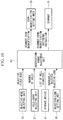
- FIG. 1 is a view showing, in outline, the configuration of a microscope system according to a first embodiment of the present invention.
- FIG. 2 is a view showing example GUIs displayed on a monitor shown in FIG. 1 .
- FIG. 3 is a block diagram for explaining processing performed by an observation-range adjustment unit.
- FIG. 4 is a flowchart for explaining a calculation method for calculating the optimum zoom magnification of a scanner and the optimum objective magnification of an objective lens.
- FIG. 7 is a view showing an example observation range when a conventional microscope system is used.
- FIG. 8 is a view showing an example observation range when a 1.25 ⁇ dry objective lens is used in an objective change mode by the microscope system shown in FIG. 1 .
- FIG. 9 is a view showing an example observation range when a 4 ⁇ dry objective lens is used in the objective change mode by the microscope system shown in FIG. 1 .
- FIG. 10 is a block diagram for explaining processing performed by the observation-range adjustment unit.
- FIG. 11 is a flowchart for explaining a calculation method for calculating the optimum zoom magnification of the scanner.
- FIG. 12 is a view showing an example observation range when a conventional microscope system is used.
- FIG. 13 is a view showing an example observation range when a 4 ⁇ dry objective lens is used in an objective fixed mode by the microscope system shown in FIG. 1 .
- FIG. 14 is a view showing, in outline, the configuration of a microscope system according to a modification of the above-described embodiments.
- a microscope system 1 of this embodiment is provided with a microscope body 3 , a control PC 5 that controls the microscope body 3 , and a monitor 7 that displays various types of information and images.
- An input unit (not shown), such as a mouse or a keyboard, that allows a user to input an instruction is connected to the control PC 5 .
- the microscope body 3 is provided with: a stage 11 on which a specimen S is placed; a laser light source 13 that produces laser light (illumination light); a scanner (scanning unit) 15 that scans laser light produced by the laser light source 13 ; a plurality of objective lenses 17 each of which radiates laser light scanned by the scanner 15 onto the specimen S and that collects fluorescence (observation light) from the specimen S; a revolver 19 that holds the plurality of objective lenses 17 ; a dichroic mirror 21 that splits off fluorescence collected by the objective lens 17 and returning along the optical path of the laser light, from the optical path of the laser light; a pinhole 23 that allows, of the fluorescence split off from the optical path of laser light by the dichroic mirror 21 , fluorescence that has been produced at the focus position, in the specimen S, of the objective lens 17 , to pass therethrough; and a detecting unit (image acquisition unit) 25 , such as a photomultiplier tube, that detects the fluorescence passing through the
- the stage 11 Under the control of the control PC 5 , the stage 11 can be moved two-dimensionally in X and Y directions intersecting the optical axis of the objective lens 17 .
- the scanner 15 As the scanner 15 , a galvanometer scanner, a resonant scanner, or the like is used, for example. Under the control of the control PC 5 , the scanner 15 can expand or narrow the scanning range of laser light.
- the objective lenses 17 for example, various types of objective lenses having different magnifications and media, such as 1.25 ⁇ dry, 4 ⁇ dry, 10 ⁇ dry, 20 ⁇ dry, 20 ⁇ oil, and 30 ⁇ silicon oil, are provided.
- the revolver 19 selectively disposes one of the multiple types of objective lenses 17 , on the optical path of fluorescence.
- the dichroic mirror 21 reflects laser light from the laser light source 13 toward the scanner 15 and allows fluorescence returning, on the optical path of laser light, from the specimen S via the scanner 15 to transmit therethrough toward the pinhole 23 .
- Microscope control software 44 is installed in the control PC 5 .
- the microscope control software 44 As shown in FIGS. 2 and 3 , the following GUIs for allowing a user to set parameters are displayed on the monitor 7 : a hole-count selecting unit 27 , an observation-range automatic-setting instructing unit 29 , a well specifying unit 31 , an objective-mode selecting unit (mode switching unit) 33 , an objective-lens setting unit 35 , an observation-range display unit 37 , and a zoom-magnification setting unit 39 .
- the hole-count selecting unit 27 allows a user to select the number (hole count) of wells (accommodation parts) in a microplate (vessel).
- the microscope system 1 holds, in advance, data in which the numbers of wells and well diameters are associated, and, when the user selects the number of wells, the well diameter is determined.
- the observation-range automatic-setting instructing unit 29 functions as a start button for instructing automatic setting of an observation range.
- the well specifying unit 31 allows the user to specify a well serving as an observation target.
- reference sign W indicates a well.
- the objective-mode selecting unit 33 allows the user to select between an objective fixed mode (fixed mode) in which the objective lens 17 currently disposed on the optical path of fluorescence is used and an objective change mode (change mode) in which one of all objective lenses 17 held by the revolver 19 is selected and is used.
- an objective fixed mode fixed mode
- an objective change mode change mode
- the objective change mode is set, when an immersion objective lens (for example, 20 ⁇ oil, 30 ⁇ silicon oil) is set on the optical path, the mode is automatically switched to the objective fixed mode. Furthermore, when an immersion objective lens is set on the optical path, the user cannot switch from the objective fixed mode to the objective change mode. On the other hand, when a dry objective lens (for example, 1.25 ⁇ dry, 4 ⁇ dry, 10 ⁇ dry, 20 ⁇ dry) is set on the optical path, the user can select either one of the objective change mode and the objective fixed mode.
- an immersion objective lens for example, 20 ⁇ oil, 30 ⁇ silicon oil
- a dry objective lens for example, 1.25 ⁇ dry, 4 ⁇ dry, 10 ⁇ dry, 20 ⁇ dry
- the objective-lens setting unit 35 allows the user to set an objective lens 17 to be used.
- the observation-range display unit 37 displays the observation range of the specimen S.
- the zoom-magnification setting unit 39 displays the zoom magnification of the scanner 15 .
- control PC 5 is provided with: a storage device 41 that stores various types of information; an observation-range adjustment unit 43 that adjusts the observation range of the specimen S on the basis of parameters set by the user by means of the GUIs; and a stage control unit 45 that controls the stage 11 .
- the observation-range adjustment unit 43 and the stage control unit 45 are held by the installed microscope control software 44 .
- the storage device 41 stores a list of well diameters according to the microplate types and a list of information about the magnifications and the media of the objective lenses 17 held by the revolver 19 .
- the observation-range adjustment unit 43 adjusts the observation range of the specimen S on the basis of an observation-range adjustment program and divides the observation range into at least one observation region corresponding to the capture range captured by the detecting unit 25 .
- reference sign A indicates an observation range
- reference sign F indicates observation regions.
- the observation-range adjustment unit 43 extracts, from the storage device 41 , objective lenses 17 that serve as calculation targets, in the form of a list of switchable objective lenses.
- dry objective lenses 17 when any of the dry objective lenses 17 is currently selected, only dry objective lenses are extracted as candidates.
- a 1.25 ⁇ dry objective lens 17 , a 4 ⁇ dry objective lens 17 , a 10 ⁇ dry objective lens 17 , and a 20 ⁇ dry objective lens 17 are extracted.
- the observation-range adjustment unit 43 calculates observation magnifications at which the entire well is included in the observation range, the number of observation regions is minimized, and the resolution becomes the highest, on the basis of information about the size of a well in the microplate specified by the user and information of a list of the extracted objective lenses. Calculated as the observation magnifications are: the zoom magnification of the scanner 15 ; and the objective magnification of the objective lens 17 to be used. Then, the observation-range adjustment unit 43 adjusts the observation range of the specimen S on the basis of the calculated zoom magnification of the scanner 15 and objective magnification of the objective lens 17 .
- the stage control unit 45 moves the stage 11 two-dimensionally in the X and Y directions, for each observation region divided by the observation-range adjustment unit 43 , so as to locate the optical axis of the objective lens 17 at the center of that observation region, on the basis of a stage control program.
- the user selects the number of holes in the microplate by means of the hole-count selecting unit 27 on the monitor 7 .
- 24 is selected as the number of holes, and thus, 24 wells W are displayed on the well specifying unit 31 .
- the user specifies a well W that serves as an observation target, by means of the well specifying unit 31 on the monitor 7 .
- the user sets the objective change mode by means of the objective-mode selecting unit 33 on the monitor 7 .
- the observation-range adjustment unit 43 executes processing on the basis of the observation-range adjustment program.
- the observation-range adjustment unit 43 reads a list of well diameters from the storage device 41 , as shown in FIG. 3 , checks, against the list, the hole-count information of the microplate selected by means of the hole-count selecting unit 27 , and determines the diameter of the well specified as an observation target.
- the observation-range adjustment unit 43 reads a list of objective lenses from the storage device 41 , reads information about the currently selected objective lens 17 from the objective-lens setting unit 35 , and extracts objective lenses 17 that serve as calculation targets, in the form of a list of switchable objective lenses.
- the observation-range adjustment unit 43 extracts the 1.25 ⁇ dry objective lens 17 , the 4 ⁇ dry objective lens 17 , the 10 ⁇ dry objective lens 17 , and the 20 ⁇ dry objective lens 17 , in the form of a list of switchable objective lenses.
- the observation-range adjustment unit 43 calculates the optimum zoom magnification of the scanner 15 and the optimum objective magnification of the objective lens 17 , from the determined well diameter and the extracted list of switchable objective lenses.
- a method for calculating the optimum zoom magnification of the scanner 15 and the optimum objective magnification of the objective lens 17 , used by the observation-range adjustment unit 43 , will be described below with reference to a flowchart of FIG. 4 .
- the list of objective lenses is searched for an objective lens 17 that has an objective magnification at which the well diameter 2r ( ⁇ m) does not exceed the length L1 ( ⁇ m) of a side of the observation region obtained when the zoom magnification of the scanner 15 is 1 ⁇ , i.e., at which L1 ⁇ 2r is satisfied (Step SA 1 ).
- MO is the objective magnification of the currently selected objective lens 17 .
- the observation-range adjustment unit 43 divides the observation range A into one observation region F, as shown in FIGS. 5A and 5B , for example.
- MZ is the zoom magnification of the scanner 15 to be calculated.
- the zoom magnification is reduced by the fraction such that the well is included in the observation range A.
- the number of decimal digits to be rounded down may be desirably set by the user.
- Step SA 1 if there is no objective lens 17 that has an objective magnification for satisfying L1 ⁇ 2r, the minimum number of observation regions a in the X and Y directions for satisfying L1 ⁇ a ⁇ 2r is determined among all objective lenses 17 held by the revolver 19 (Step SA 5 ), and the objective magnification thereof is calculated.
- the observation-range adjustment unit 43 divides the observation range into four observation regions F, as shown in FIGS. 6A and 6B .
- the objective lens 17 that has the highest objective magnification is selected (in this case, FIG. 6B ), and, if there is only one objective lens 17 that has such an objective magnification, that objective lens 17 is selected (Step SA 6 ).
- the zoom magnification is reduced by the fraction such that the well is included in the observation range A.
- the number of observation regions a in the X and Y directions is set to 1, or the number of observation regions a is set to the minimum even if a cannot be set to 1, thereby making it possible to reduce the time required for image acquisition as much as possible.
- the zoom magnification is set to a value at which the observation range becomes substantially equal to the outer diameter of the well, thereby making it possible to reduce unnecessary imaging of a region outside the well, thus improving the resolution, compared with a zoom magnification at which the observation range becomes larger than the outer diameter of the well.
- the observation-range adjustment unit 43 sends information about the calculated zoom magnification of the scanner 15 to the zoom-magnification setting unit 39 and also sends information about the calculated objective magnification of the objective lens 17 to the objective-lens setting unit 35 , as shown in FIG. 3 .
- the observation-range adjustment unit 43 sends the observation range to the observation-range display unit 37 and, at the same time, instructs the scanner 15 to switch the zoom magnification and instructs the revolver 19 to switch the objective lens 17 . Accordingly, new zoom magnification and objective lens 17 are selected, the observation range is divided into a x a observation areas in the X and Y directions, and a region located outside the well is deleted, thus changing the observation range to an observation range that is close to the outer diameter of the well.
- the length of a side of the observation region becomes 1.27 mm.
- the currently selected objective lens 17 having the objective magnification of 10 ⁇ is still used, and, as shown in FIG. 7 , the number of observation regions F required to acquire an observation image of the entire well W becomes 25.
- the observation-range adjustment unit 43 sets the 1.25 ⁇ dry objective lens 17 and sets the zoom magnification of the scanner 15 to 1.6 ⁇ .
- the number of observation regions F is one, and the observation range A that is close to the outer diameter of the well W is set. If the 1.25 ⁇ dry objective lens 17 is not provided, the 4 ⁇ dry objective lens 17 is set, and the zoom magnification of the scanner 15 is set to 1.0 ⁇ . In this case, as shown in FIG. 9 , the number of observation regions F is four, and an observation range A that is close to the outer diameter of the well W is set.
- the observation range is adjusted on the basis of the observation magnifications calculated by the observation-range adjustment unit 43 , thereby making it possible to minimize the number of observation regions required to thoroughly observe the entire well and to set an observation range for preventing imaging of an unnecessary region outside the well as much as possible. Accordingly, the inside of the well can be imaged in a shorter time because of the minimized number of observation regions and at higher resolution because of the reduced unnecessary imaging of a region outside the well due to the zoom magnification.
- Identical reference signs are assigned to components having configurations common to those in the microscope system 1 according to the first embodiment, and a description thereof will be omitted.
- the user selects the number of holes in the microplate, specifies a well that serves as an observation target, and then sets the objective fixed mode by means of the objective-mode selecting unit 33 on the monitor 7 .
- the observation-range adjustment unit 43 determines the diameter of the well specified as an observation target by the user and reads the objective magnification of the currently selected objective lens 17 from the objective-lens setting unit 35 , as shown in FIG. 10 . Then, the observation-range adjustment unit 43 calculates the optimum zoom magnification of the scanner 15 on the basis of the determined diameter of the well and the objective magnification of the currently selected objective lens 17 .
- a method for calculating the optimum zoom magnification of the scanner 15 , used by the observation-range adjustment unit 43 , will be described below with reference to a flowchart of FIG. 11 .
- Step SB 1 the minimum number of observation regions a in the X and Y directions for satisfying L1 ⁇ a ⁇ 2r is determined.
- the zoom magnification is reduced by the fraction such that the well is included in the observation range A.
- the number of observation regions a in the X and Y directions is minimized, thereby making it possible to reduce the time required for image acquisition as much as possible, and the zoom magnification is set to a value at which the observation range becomes substantially equal to the outer diameter of the well, thereby making it possible to reduce unnecessary imaging of a region outside the well, thus improving the resolution.
- the observation-range adjustment unit 43 sends information about the calculated zoom magnification of the scanner 15 to the zoom-magnification setting unit 39 , as shown in FIG. 10 . Then, the observation-range adjustment unit 43 sends the observation range to the observation-range display unit 37 and, at the same time, instructs the scanner 15 to switch the zoom magnification.
- the currently-selected 4 ⁇ dry objective lens 17 is still used, the new zoom magnification is selected, the observation range is divided into a x a observation regions in the X and Y directions, and a region located outside the well is deleted, thus changing the observation range to an observation range that is close to the outer diameter of the well.
- the length of a side of each observation region becomes 1.59 mm.
- the currently selected objective lens 17 having the objective magnification of 4 ⁇ is still used, and, as shown in FIG. 12 , the number of observation regions F required to acquire an observation image of the entire well W becomes 16.
- the observation-range adjustment unit 43 still uses the currently-selected 4 ⁇ dry objective lens 17 and sets the zoom magnification of the scanner 15 to 1 ⁇ .
- the number of observation regions F is four, and an observation range A that is close to the outer shape of the well W is set.
- the microscope system 1 of this embodiment while an objective lens 17 desired by the user is used, it is possible to minimize the number of observation regions required to thoroughly observe the entire well and to set an observation range for preventing imaging of an unnecessary region outside the well as much as possible. Accordingly, the inside of the well can be imaged in a shorter time and at high resolution.
- the detecting unit 25 such as a photomultiplier tube
- a camera 47 such as a CCD
- the observation-range adjustment unit 43 may change the zoom magnification of the variable-magnification optical system 49 .
- the same effect as those in the above-described embodiments can also be obtained.
- the present invention provides a microscope system including: a plurality of objective lenses that are selectively used to collect observation light from a specimen; an image acquisition unit that acquires an image of the specimen on the basis of the observation light collected by the objective lens; and an observation-range adjustment unit that adjusts an observation range of the specimen and that divides the observation range into one or more observation regions corresponding to a capture range captured by the image acquisition unit, wherein the observation-range adjustment unit calculates, on the basis of information about the size of an accommodation part of a vessel for accommodating the specimen and information about an objective magnification of the objective lens, an observation magnification at which the entire accommodation part is included in the observation range, the number of observation regions is minimized, and the resolution becomes the highest, and adjusts the observation range on the basis of the calculated observation magnification.
- the objective lens collects observation light from the specimen, and the image acquisition unit acquires an image.
- the observation range is adjusted on the basis of the observation magnification calculated by the observation-range adjustment unit, thereby making it possible to minimize the number of observation regions required to thoroughly observe the entire accommodation part and to set an observation range for preventing imaging of an unnecessary portion. Accordingly, the inside of the well can be imaged in a shorter time and at high resolution.
- the above-described aspect may further include a scanning unit that scans, on the specimen, illumination light produced by a light source, wherein the observation-range adjustment unit may change a zoom magnification used by the scanning unit, on the basis of the observation magnification.
- the zoom magnification of the scanning unit is reduced, the scanning range of illumination light is expanded, and as the zoom magnification thereof is increased, the scanning range of illumination light is narrowed. Therefore, with this configuration, the observation range can be easily adjusted with a simple configuration in which only the zoom magnification of the scanning unit is changed.
- the above-described aspect may further include a variable-magnification optical system, wherein the observation-range adjustment unit may change a zoom magnification of the variable-magnification optical system on the basis of the observation magnification.
- the observation range As the zoom magnification of the variable-magnification optical system is reduced, the observation range is expanded, and, as the zoom magnification thereof is increased, the observation range is narrowed. With this configuration, the observation range can be easily adjusted with a simple configuration in which only the zoom magnification of the variable-magnification optical system is changed.
- the plurality of objective lenses may have objective magnifications different from each other; and the observation-range adjustment unit may change the objective lens to be disposed on the optical path of the observation light.
- the number of observation regions into which the observation range is divided is determined according to the relationship between the size of the accommodation part and the objective magnification of the objective lens to be used; therefore, with this configuration, the observation range can be divided by the number of observation regions corresponding to the objective magnification of the objective lens disposed on the optical path of the observation light.
- the above-described aspect may further include a mode switching unit that can switch between a fixed mode in which the objective lens that is disposed on the optical path of the observation light is used and a change mode in which any of the plurality of objective lenses is selected and is used, wherein, in the fixed mode, the observation-range adjustment unit may divide the observation range on the basis of the objective magnification of the objective lens that is disposed on the optical path of the observation light and, in the change mode, may divide the observation range on the basis of the objective magnification of the objective lens, among the plurality of objective lenses, at which the entire accommodation part is included in the observation range and at which the number of observation regions is minimized.
- an objective lens desired by the user is used in the fixed mode, and an objective lens, among the plurality of provided objective lenses, with which the number of observation regions is minimized is used in the change mode, thereby making it possible to minimize the number of observation regions required to thoroughly observe the entire well and to set an observation range for preventing imaging of an unnecessary portion.
- the mode may be automatically switched to the fixed mode.
- an immersion objective lens is set on the optical path, it is possible to prevent the user from switching from the fixed mode to the change mode.
- a dry objective lens is set on the optical path, it is possible to allow the user to select either one of the change mode and the fixed mode.
- the above-described aspect may further include: a stage on which the specimen is placed and that can be moved in a direction intersecting the optical axis of the objective lens; and a stage control unit that moves, in each of the observation regions divided by the observation-range adjustment unit, the stage so as to locate the optical axis of the objective lens at the center of that observation region.
- the image acquisition unit can acquire images of the specimen, thus generating an image over the entire observation range.
Abstract
Description
- 1 microscope system
- 11 stage
- 15 scanner (scanning unit)
- 17 objective lens
- 25 detecting unit (image acquisition unit)
- 33 objective-mode selecting unit (mode switching unit)
- 43 observation-range adjustment unit
- 45 stage control unit
- 47 camera (image acquisition unit)
- 49 variable-magnification optical system
- S specimen
- W well (accommodation part)
Claims (12)
Applications Claiming Priority (2)
| Application Number | Priority Date | Filing Date | Title |
|---|---|---|---|
| JP2016-153929 | 2016-08-04 | ||
| JP2016153929A JP2018022072A (en) | 2016-08-04 | 2016-08-04 | Microscope system |
Publications (2)
| Publication Number | Publication Date |
|---|---|
| US20180039059A1 US20180039059A1 (en) | 2018-02-08 |
| US10539774B2 true US10539774B2 (en) | 2020-01-21 |
Family
ID=61069188
Family Applications (1)
| Application Number | Title | Priority Date | Filing Date |
|---|---|---|---|
| US15/645,175 Active 2038-01-18 US10539774B2 (en) | 2016-08-04 | 2017-07-10 | Microscope system |
Country Status (2)
| Country | Link |
|---|---|
| US (1) | US10539774B2 (en) |
| JP (1) | JP2018022072A (en) |
Families Citing this family (3)
| Publication number | Priority date | Publication date | Assignee | Title |
|---|---|---|---|---|
| JP6455829B2 (en) * | 2013-04-01 | 2019-01-23 | キヤノン株式会社 | Image processing apparatus, image processing method, and program |
| JP2020502558A (en) | 2016-11-10 | 2020-01-23 | ザ トラスティーズ オブ コロンビア ユニバーシティ イン ザ シティ オブ ニューヨーク | High-speed, high-resolution imaging method for large samples |
| DE102018128281B3 (en) * | 2018-11-12 | 2019-11-14 | Leica Microsystems Cms Gmbh | Microscope system and method for examining a sample |
Citations (2)
| Publication number | Priority date | Publication date | Assignee | Title |
|---|---|---|---|---|
| US20090015911A1 (en) * | 2007-06-22 | 2009-01-15 | Yuichiro Matsuo | Motor-operated microscope system and software for controlling motor-operated microscopes |
| JP2010216919A (en) * | 2009-03-16 | 2010-09-30 | Olympus Corp | Image pickup device and cell image analyzing system equipped with the same |
-
2016
- 2016-08-04 JP JP2016153929A patent/JP2018022072A/en active Pending
-
2017
- 2017-07-10 US US15/645,175 patent/US10539774B2/en active Active
Patent Citations (2)
| Publication number | Priority date | Publication date | Assignee | Title |
|---|---|---|---|---|
| US20090015911A1 (en) * | 2007-06-22 | 2009-01-15 | Yuichiro Matsuo | Motor-operated microscope system and software for controlling motor-operated microscopes |
| JP2010216919A (en) * | 2009-03-16 | 2010-09-30 | Olympus Corp | Image pickup device and cell image analyzing system equipped with the same |
Also Published As
| Publication number | Publication date |
|---|---|
| JP2018022072A (en) | 2018-02-08 |
| US20180039059A1 (en) | 2018-02-08 |
Similar Documents
| Publication | Publication Date | Title |
|---|---|---|
| EP2256534B1 (en) | In-vivo examination apparatus | |
| JP6158197B2 (en) | Multifunction autofocus system and method for automated microscope use | |
| JP5863357B2 (en) | Magnification observation apparatus, and image display method and spectroscopic method switching method of magnification observation apparatus | |
| KR102411099B1 (en) | Real-time autofocus scanning | |
| JP4973162B2 (en) | Image processing apparatus, image processing program, and observation system | |
| US10539774B2 (en) | Microscope system | |
| CN111788508B (en) | Digital microscope and method for changing the magnification of a digital microscope | |
| US20140267675A1 (en) | Digital microscope apparatus, imaging method therefor, and program | |
| US8994806B2 (en) | Microscope apparatus chronologically storing different types of image information | |
| JP6548965B2 (en) | Microscope system and microscopic observation method | |
| JP2023065612A (en) | System and method for managing plural scanning devices in high-throughput laboratory environment | |
| JP2017156207A (en) | Imaging device and imaging method | |
| US7078664B2 (en) | Confocal laser microscope displaying target images side by side | |
| CN114303086A (en) | Apparatus and method for imaging an object | |
| JP7086057B2 (en) | Microscope system | |
| JP2018105936A (en) | Microscope and method for supporting setting | |
| JP2015082099A (en) | Control apparatus for controlling microscope, microscope system, control method, and program | |
| JP6848086B2 (en) | Observation device and method and observation device control program | |
| JP6062028B2 (en) | Magnification observation apparatus and magnification observation method | |
| JP5281763B2 (en) | Control device, magnification observation system, and method for controlling magnification observation device | |
| JP2009092795A (en) | Method for adjusting lightness of image in imaging type microscope device | |
| JP2004185005A (en) | Transmitted light illumination unit of microscope | |
| JP7251957B2 (en) | Magnifying observation device | |
| US10404965B2 (en) | Microscope system | |
| EP3748413A1 (en) | Control unit for a microscope, microscope system including such control unit and method of examining a sample |
Legal Events
| Date | Code | Title | Description |
|---|---|---|---|
| AS | Assignment |
Owner name: OLYMPUS CORPORATION, JAPAN Free format text: ASSIGNMENT OF ASSIGNORS INTEREST;ASSIGNORS:KONDO, KANAKO;TAKAMIZAWA, NOBUHIRO;SIGNING DATES FROM 20170609 TO 20170610;REEL/FRAME:042952/0102 |
|
| STPP | Information on status: patent application and granting procedure in general |
Free format text: NON FINAL ACTION MAILED |
|
| STPP | Information on status: patent application and granting procedure in general |
Free format text: RESPONSE TO NON-FINAL OFFICE ACTION ENTERED AND FORWARDED TO EXAMINER |
|
| STPP | Information on status: patent application and granting procedure in general |
Free format text: NOTICE OF ALLOWANCE MAILED -- APPLICATION RECEIVED IN OFFICE OF PUBLICATIONS |
|
| STPP | Information on status: patent application and granting procedure in general |
Free format text: PUBLICATIONS -- ISSUE FEE PAYMENT RECEIVED |
|
| STCF | Information on status: patent grant |
Free format text: PATENTED CASE |
|
| AS | Assignment |
Owner name: EVIDENT CORPORATION, JAPAN Free format text: ASSIGNMENT OF ASSIGNORS INTEREST;ASSIGNOR:OLYMPUS CORPORATION;REEL/FRAME:062492/0267 Effective date: 20221024 |
|
| MAFP | Maintenance fee payment |
Free format text: PAYMENT OF MAINTENANCE FEE, 4TH YEAR, LARGE ENTITY (ORIGINAL EVENT CODE: M1551); ENTITY STATUS OF PATENT OWNER: LARGE ENTITY Year of fee payment: 4 |