US1053857A - Shell-fuse with safety device. - Google Patents
Shell-fuse with safety device. Download PDFInfo
- Publication number
- US1053857A US1053857A US68947212A US1912689472A US1053857A US 1053857 A US1053857 A US 1053857A US 68947212 A US68947212 A US 68947212A US 1912689472 A US1912689472 A US 1912689472A US 1053857 A US1053857 A US 1053857A
- Authority
- US
- United States
- Prior art keywords
- fuse
- shell
- safety device
- hammer
- slot
- Prior art date
- Legal status (The legal status is an assumption and is not a legal conclusion. Google has not performed a legal analysis and makes no representation as to the accuracy of the status listed.)
- Expired - Lifetime
Links
- 238000010304 firing Methods 0.000 description 5
- 230000001133 acceleration Effects 0.000 description 2
- 238000004880 explosion Methods 0.000 description 2
- 241000845082 Panama Species 0.000 description 1
- 239000002131 composite material Substances 0.000 description 1
- 239000002360 explosive Substances 0.000 description 1
- 230000000284 resting effect Effects 0.000 description 1
- 230000000979 retarding effect Effects 0.000 description 1
Images
Classifications
-
- F—MECHANICAL ENGINEERING; LIGHTING; HEATING; WEAPONS; BLASTING
- F42—AMMUNITION; BLASTING
- F42C—AMMUNITION FUZES; ARMING OR SAFETY MEANS THEREFOR
- F42C15/00—Arming-means in fuzes; Safety means for preventing premature detonation of fuzes or charges
- F42C15/24—Arming-means in fuzes; Safety means for preventing premature detonation of fuzes or charges wherein the safety or arming action is effected by inertia means
- F42C15/26—Arming-means in fuzes; Safety means for preventing premature detonation of fuzes or charges wherein the safety or arming action is effected by inertia means using centrifugal force
Definitions
- ln fuses for high explosive shells it has always been desirable that the fuse shall remain inoperative, i'. e. that it shall not be possible to bring the charge to explosion, before the projectile has passed not only through the barrel but also to a certain distance in 'l'i-ont of the mouth of the gun.
- a longitudinally movable, simple or composite'member has been used, said member being moved forward when the acN celeration of the projectile ceases, either on account of its inertia or under the .action of a compressed spring or both, and making the fuse operative on impact so as to permit the explosion, only after moving through a certain distance.
- the present invention has for its object to provide a device for surmounting the aforesaid inconvenience and consists in in troducing a certain determined resistance against the forward niovenient of the aforesaid longitudinally niovable member, thus retarding the said movement and the nioment in which the fuse becomes operative.
- Fig. l which shows a base fuse the stationary fuse body consists of three parts y, z, l. the last-mentioned of which embraces the (-,liargey j. 'The part 71.V Carries (he igniting needle i' aol en'ibraccs partly by means olf suilablil recesses balls (l which also engage rocosa in the hammer c carrying the ignltine ⁇ - cap the movement of said hammer thus being pi" culi-if.
- a ⁇ resistance against the movement of the part c is introduced.
- a simple arrangement for obtaining such al resistance is to cause a pin m secured to the part o to engage a slot n in the stationary fuse body L, or vice versa.
- the slot n may in some cases be straight and a sullicient resistance may still be obtained on account of the pressure and friction between the pin and the side of the slot caused by the rotation of the projectile.
- Fig. i2 illustratesan application of the invention to a point fuse
- said member moving backward at the firing of the gun and compressing the spring which after the ceasing of the acceleration -moves the member' c forward again. in this movement, the said member passes beyond its original position, because a couple of locking members o situated in front. of the same meanwhile have been removed hy'lhe centrifugal ⁇ force against the action ol' springs y resting against nuts g. lhe retardation of the movement of the spring f which upon the ceasing of the afse4.000ctingg the friction other devices may be used than pins'engaging slots.
- a hammer a' firing pin, locking members for normally preventing ⁇ Contact between said hammer and firing pinz e. longitudinally movable member for releasing said locking members, and a pin on seid longitudinally movable member engaging a curved slot in a stationary part of the fuse.
Landscapes
- Engineering & Computer Science (AREA)
- General Engineering & Computer Science (AREA)
- Portable Nailing Machines And Staplers (AREA)
- Air Bags (AREA)
Description
H. NO'RDENFELT.
SHELL FUSE WIT SAFETY DEVICE. l APPIlloATIoN FILED APB. 9. 1912.
y Panama Feb.1s`,1913.
.filiali-l r /A/vEA/Tgg;
UNITED PATENT @FF-fat@ GULLSPNG, OF BOFORS. SWEDEN.
SHELL-FUSE `W'I'IH SAFETY DEVICE.
lib-)3.357.
Application filed April 9,
Specification of Iietters Patent.
Patented Feb. 18.1591 3.
1912. Serial No. 689,472.
Tf, (f77 whom. t may concern.'
le it known that l, HENRIK Nonnen*- i-izixr` a subject of the King of Sweden, residing at Bofors, Sweden, have invented new and useful Improvements in Shell- Fuses with Safety Devices, of which the following is a specification.
ln fuses for high explosive shells it has always been desirable that the fuse shall remain inoperative, i'. e. that it shall not be possible to bring the charge to explosion, before the projectile has passed not only through the barrel but also to a certain distance in 'l'i-ont of the mouth of the gun. For this purpose, a longitudinally movable, simple or composite'member has been used, said member being moved forward when the acN celeration of the projectile ceases, either on account of its inertia or under the .action of a compressed spring or both, and making the fuse operative on impact so as to permit the explosion, only after moving through a certain distance. lt has however been found, that in using such a safety device well as all those known heretofore which are based only upon mechanical principles the distance in front of the barrel mouth through which\ the projectile travels before being made operative only will amount to a few meters, the safety for the service men of the gun thus being unsatisfactory.
The present invention has for its object to provide a device for surmounting the aforesaid inconvenience and consists in in troducing a certain determined resistance against the forward niovenient of the aforesaid longitudinally niovable member, thus retarding the said movement and the nioment in which the fuse becomes operative.
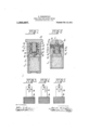
The invention is illustrated in the accompanying drawing whereV4 Figures l and 2 show two different forms of fuses embodying the same in a longitudinal section and l"ig;s.. -5 three different forms of members characteristic to the involition.
ln Fig. l which shows a base fuse the stationary fuse body consists of three parts y, z, l. the last-mentioned of which embraces the (-,liargey j. 'The part 71.V Carries (he igniting needle i' aol en'ibraccs partly by means olf suilablil recesses balls (l which also engage rocosa in the hammer c carrying the ignltine`- cap the movement of said hammer thus being pi" culi-if. The balls Il aro hcld I against vmoving out of the recesses in the l hammer e by means of a surrounding ring or sleeve Vhen the gun is fired, a sleeve a. surrounding the Sleeve c is moved backward on account of its inertia and compresses a celeration again moves the sleeve o forward, the said sleeve having meanwhile been coupled to the sleeve c by means of a resilient tiange so as to carry forth the latter when moving forward. The balls CZ then are released and are thrown out by the centrifugal force, whereupon the fuse is operative, the hammer now being kept away from the igniting needle Z only by the weak spring b.
As the forward movement of the parts a and o, as above stated, begins as soon the acceleration of the projectile has ceased, or even somewhat before this moment, the operative condition of the fuse will be reached too soonif no special steps are taken to prevent this circumstance. According to the present invention, such steps are taken in that a` resistance against the movement of the part c is introduced. A simple arrangement for obtaining such al resistance is to cause a pin m secured to the part o to engage a slot n in the stationary fuse body L, or vice versa. The slot n may in some cases be straight and a sullicient resistance may still be obtained on account of the pressure and friction between the pin and the side of the slot caused by the rotation of the projectile. ln other cases, it may be found suitable to make the slot ciufved or its walls uneven for obtaining the necesary increased resistance against the movement of the part c. Dif-V ferent examples of this principle are shown in Figs, 315-5. By an appropriate shape of the slot the entering of the operative state of the fuse can be retarded at will.
Fig. i2 illustratesan application of the invention to a point fuse, Further, in this form only one longitudinally movable member c is present, said member moving backward at the firing of the gun and compressing the spring which after the ceasing of the acceleration -moves the member' c forward again. in this movement, the said member passes beyond its original position, because a couple of locking members o situated in front. of the same meanwhile have been removed hy'lhe centrifugal` force against the action ol' springs y resting against nuts g. lhe retardation of the movement of the spring f which upon the ceasing of the afseiilectingg the friction other devices may be used than pins'engaging slots. *L
Having now particularly described the 11atui'e of my invention and the manner of its operation, what claim is: l. In safety devices for shell fuses, a hammerA e firing pin7 locking members for normally preventing Contact between said hammer and firing pin7 a longitudinlly movable member for releasing said locking members, and a pin onKsaid longitudinally movable member engaging a slot in a stationary part of the fuse.
2. In safety devices for shell fuses, a hammer a' firing pin, locking members for normally preventing` Contact between said hammer and firing pinz e. longitudinally movable member for releasing said locking members, and a pin on seid longitudinally movable member engaging a curved slot in a stationary part of the fuse. Y Y
In testimony whereof I have signed my name to this specification in. the presence of two subscribing Witnesses.
HENRIK NORDENFELT. Witnesses A. R. ENGBURG, EMIL-Olsson.
Priority Applications (1)
| Application Number | Priority Date | Filing Date | Title |
|---|---|---|---|
| US68947212A US1053857A (en) | 1912-04-09 | 1912-04-09 | Shell-fuse with safety device. |
Applications Claiming Priority (1)
| Application Number | Priority Date | Filing Date | Title |
|---|---|---|---|
| US68947212A US1053857A (en) | 1912-04-09 | 1912-04-09 | Shell-fuse with safety device. |
Publications (1)
| Publication Number | Publication Date |
|---|---|
| US1053857A true US1053857A (en) | 1913-02-18 |
Family
ID=3122117
Family Applications (1)
| Application Number | Title | Priority Date | Filing Date |
|---|---|---|---|
| US68947212A Expired - Lifetime US1053857A (en) | 1912-04-09 | 1912-04-09 | Shell-fuse with safety device. |
Country Status (1)
| Country | Link |
|---|---|
| US (1) | US1053857A (en) |
Cited By (4)
| Publication number | Priority date | Publication date | Assignee | Title |
|---|---|---|---|---|
| US2595757A (en) * | 1946-11-02 | 1952-05-06 | Energa | Fuse |
| US2712284A (en) * | 1951-06-19 | 1955-07-05 | Haroid E Thomas | Delayed arming safety fuse |
| US2772635A (en) * | 1952-09-15 | 1956-12-04 | Belge De Mecanique Et D Armeme | Rifle grenade |
| US2925778A (en) * | 1957-03-15 | 1960-02-23 | Stewart Warner Corp | Helix type delay detent |
-
1912
- 1912-04-09 US US68947212A patent/US1053857A/en not_active Expired - Lifetime
Cited By (4)
| Publication number | Priority date | Publication date | Assignee | Title |
|---|---|---|---|---|
| US2595757A (en) * | 1946-11-02 | 1952-05-06 | Energa | Fuse |
| US2712284A (en) * | 1951-06-19 | 1955-07-05 | Haroid E Thomas | Delayed arming safety fuse |
| US2772635A (en) * | 1952-09-15 | 1956-12-04 | Belge De Mecanique Et D Armeme | Rifle grenade |
| US2925778A (en) * | 1957-03-15 | 1960-02-23 | Stewart Warner Corp | Helix type delay detent |
Similar Documents
| Publication | Publication Date | Title |
|---|---|---|
| US2537855A (en) | Point contact fuse | |
| GB1213865A (en) | Projectile fuze with improved time delay and self-destroying mechanism | |
| US3603259A (en) | Fuze setback and angular acceleration detent | |
| US3371608A (en) | Fuze with delay firing and impact firing features | |
| GB1218884A (en) | Hand-grenade and land mine | |
| US3842740A (en) | Hand grenade detonator | |
| US2825284A (en) | Impact fuzes with mechanical retardation | |
| US3033115A (en) | Nose fuzes of the percussion type including a self-destruction device | |
| US3765340A (en) | Arming and unarming device | |
| ES8204849A1 (en) | Fuse for spinning projectiles. | |
| US3961578A (en) | Point-detonating projectile fuze | |
| US1768678A (en) | Fuse for trench-mortar projectiles | |
| US2859696A (en) | Hydrostatically operated firing device | |
| US1280521A (en) | Fuse for high-explosive shells. | |
| US1216834A (en) | Shell-fuse. | |
| US1455741A (en) | Fuse | |
| GB725821A (en) | Improvements in explosive armour piercing projectiles | |
| US3146714A (en) | Delay fuze for rotating munition | |
| US2966856A (en) | Magnetic detonator | |
| US1205921A (en) | Safety device for shell-fuses. | |
| US2741183A (en) | Centrifugal projectile fuze | |
| US3376819A (en) | Explosive appliances with a delay mechanism | |
| US775861A (en) | Fuse for projectiles. | |
| US1169747A (en) | Fuse for high-explosive shells. | |
| US2988995A (en) | Projectile fuze |