US10537032B2 - Mounting structure for display screen - Google Patents
Mounting structure for display screen Download PDFInfo
- Publication number
- US10537032B2 US10537032B2 US15/028,397 US201515028397A US10537032B2 US 10537032 B2 US10537032 B2 US 10537032B2 US 201515028397 A US201515028397 A US 201515028397A US 10537032 B2 US10537032 B2 US 10537032B2
- Authority
- US
- United States
- Prior art keywords
- outer frame
- panel
- locking
- tongue
- key
- Prior art date
- Legal status (The legal status is an assumption and is not a legal conclusion. Google has not performed a legal analysis and makes no representation as to the accuracy of the status listed.)
- Active, expires
Links
Images


Classifications
-
- H—ELECTRICITY
- H05—ELECTRIC TECHNIQUES NOT OTHERWISE PROVIDED FOR
- H05K—PRINTED CIRCUITS; CASINGS OR CONSTRUCTIONAL DETAILS OF ELECTRIC APPARATUS; MANUFACTURE OF ASSEMBLAGES OF ELECTRICAL COMPONENTS
- H05K5/00—Casings, cabinets or drawers for electric apparatus
- H05K5/0017—Casings, cabinets or drawers for electric apparatus with operator interface units
-
- A—HUMAN NECESSITIES
- A47—FURNITURE; DOMESTIC ARTICLES OR APPLIANCES; COFFEE MILLS; SPICE MILLS; SUCTION CLEANERS IN GENERAL
- A47B—TABLES; DESKS; OFFICE FURNITURE; CABINETS; DRAWERS; GENERAL DETAILS OF FURNITURE
- A47B81/00—Cabinets or racks specially adapted for other particular purposes, e.g. for storing guns or skis
- A47B81/06—Furniture aspects of radio, television, gramophone, or record cabinets
-
- A—HUMAN NECESSITIES
- A47—FURNITURE; DOMESTIC ARTICLES OR APPLIANCES; COFFEE MILLS; SPICE MILLS; SUCTION CLEANERS IN GENERAL
- A47B—TABLES; DESKS; OFFICE FURNITURE; CABINETS; DRAWERS; GENERAL DETAILS OF FURNITURE
- A47B97/00—Furniture or accessories for furniture, not provided for in other groups of this subclass
- A47B97/001—Wall mounting or suspension arrangements for blackboards or the like
-
- E—FIXED CONSTRUCTIONS
- E05—LOCKS; KEYS; WINDOW OR DOOR FITTINGS; SAFES
- E05B—LOCKS; ACCESSORIES THEREFOR; HANDCUFFS
- E05B15/00—Other details of locks; Parts for engagement by bolts of fastening devices
- E05B15/08—Key guides; Key pins ; Keyholes; Keyhole finders
-
- E—FIXED CONSTRUCTIONS
- E05—LOCKS; KEYS; WINDOW OR DOOR FITTINGS; SAFES
- E05B—LOCKS; ACCESSORIES THEREFOR; HANDCUFFS
- E05B19/00—Keys; Accessories therefor
- E05B19/0017—Key profiles
-
- F—MECHANICAL ENGINEERING; LIGHTING; HEATING; WEAPONS; BLASTING
- F16—ENGINEERING ELEMENTS AND UNITS; GENERAL MEASURES FOR PRODUCING AND MAINTAINING EFFECTIVE FUNCTIONING OF MACHINES OR INSTALLATIONS; THERMAL INSULATION IN GENERAL
- F16M—FRAMES, CASINGS OR BEDS OF ENGINES, MACHINES OR APPARATUS, NOT SPECIFIC TO ENGINES, MACHINES OR APPARATUS PROVIDED FOR ELSEWHERE; STANDS; SUPPORTS
- F16M11/00—Stands or trestles as supports for apparatus or articles placed thereon ; Stands for scientific apparatus such as gravitational force meters
- F16M11/20—Undercarriages with or without wheels
- F16M11/22—Undercarriages with or without wheels with approximately constant height, e.g. with constant length of column or of legs
-
- F—MECHANICAL ENGINEERING; LIGHTING; HEATING; WEAPONS; BLASTING
- F16—ENGINEERING ELEMENTS AND UNITS; GENERAL MEASURES FOR PRODUCING AND MAINTAINING EFFECTIVE FUNCTIONING OF MACHINES OR INSTALLATIONS; THERMAL INSULATION IN GENERAL
- F16M—FRAMES, CASINGS OR BEDS OF ENGINES, MACHINES OR APPARATUS, NOT SPECIFIC TO ENGINES, MACHINES OR APPARATUS PROVIDED FOR ELSEWHERE; STANDS; SUPPORTS
- F16M13/00—Other supports for positioning apparatus or articles; Means for steadying hand-held apparatus or articles
- F16M13/02—Other supports for positioning apparatus or articles; Means for steadying hand-held apparatus or articles for supporting on, or attaching to, an object, e.g. tree, gate, window-frame, cycle
-
- G—PHYSICS
- G09—EDUCATION; CRYPTOGRAPHY; DISPLAY; ADVERTISING; SEALS
- G09F—DISPLAYING; ADVERTISING; SIGNS; LABELS OR NAME-PLATES; SEALS
- G09F9/00—Indicating arrangements for variable information in which the information is built-up on a support by selection or combination of individual elements
- G09F9/30—Indicating arrangements for variable information in which the information is built-up on a support by selection or combination of individual elements in which the desired character or characters are formed by combining individual elements
- G09F9/33—Indicating arrangements for variable information in which the information is built-up on a support by selection or combination of individual elements in which the desired character or characters are formed by combining individual elements being semiconductor devices, e.g. diodes
-
- H—ELECTRICITY
- H05—ELECTRIC TECHNIQUES NOT OTHERWISE PROVIDED FOR
- H05K—PRINTED CIRCUITS; CASINGS OR CONSTRUCTIONAL DETAILS OF ELECTRIC APPARATUS; MANUFACTURE OF ASSEMBLAGES OF ELECTRICAL COMPONENTS
- H05K5/00—Casings, cabinets or drawers for electric apparatus
- H05K5/02—Details
- H05K5/0217—Mechanical details of casings
- H05K5/0221—Locks; Latches
-
- A—HUMAN NECESSITIES
- A47—FURNITURE; DOMESTIC ARTICLES OR APPLIANCES; COFFEE MILLS; SPICE MILLS; SUCTION CLEANERS IN GENERAL
- A47B—TABLES; DESKS; OFFICE FURNITURE; CABINETS; DRAWERS; GENERAL DETAILS OF FURNITURE
- A47B97/00—Furniture or accessories for furniture, not provided for in other groups of this subclass
- A47B2097/005—Monitor mounted supports or stands
-
- F16B2001/0035—
-
- F16B2001/0064—
-
- F—MECHANICAL ENGINEERING; LIGHTING; HEATING; WEAPONS; BLASTING
- F16—ENGINEERING ELEMENTS AND UNITS; GENERAL MEASURES FOR PRODUCING AND MAINTAINING EFFECTIVE FUNCTIONING OF MACHINES OR INSTALLATIONS; THERMAL INSULATION IN GENERAL
- F16B—DEVICES FOR FASTENING OR SECURING CONSTRUCTIONAL ELEMENTS OR MACHINE PARTS TOGETHER, e.g. NAILS, BOLTS, CIRCLIPS, CLAMPS, CLIPS OR WEDGES; JOINTS OR JOINTING
- F16B2200/00—Constructional details of connections not covered for in other groups of this subclass
- F16B2200/83—Use of a magnetic material
-
- F—MECHANICAL ENGINEERING; LIGHTING; HEATING; WEAPONS; BLASTING
- F16—ENGINEERING ELEMENTS AND UNITS; GENERAL MEASURES FOR PRODUCING AND MAINTAINING EFFECTIVE FUNCTIONING OF MACHINES OR INSTALLATIONS; THERMAL INSULATION IN GENERAL
- F16B—DEVICES FOR FASTENING OR SECURING CONSTRUCTIONAL ELEMENTS OR MACHINE PARTS TOGETHER, e.g. NAILS, BOLTS, CIRCLIPS, CLAMPS, CLIPS OR WEDGES; JOINTS OR JOINTING
- F16B2200/00—Constructional details of connections not covered for in other groups of this subclass
- F16B2200/93—Fastener comprising feature for establishing a good electrical connection, e.g. electrostatic discharge or insulation feature
-
- F—MECHANICAL ENGINEERING; LIGHTING; HEATING; WEAPONS; BLASTING
- F16—ENGINEERING ELEMENTS AND UNITS; GENERAL MEASURES FOR PRODUCING AND MAINTAINING EFFECTIVE FUNCTIONING OF MACHINES OR INSTALLATIONS; THERMAL INSULATION IN GENERAL
- F16M—FRAMES, CASINGS OR BEDS OF ENGINES, MACHINES OR APPARATUS, NOT SPECIFIC TO ENGINES, MACHINES OR APPARATUS PROVIDED FOR ELSEWHERE; STANDS; SUPPORTS
- F16M2200/00—Details of stands or supports
- F16M2200/02—Locking means
Definitions
- the present invention relates to the field of the installation of an LED display screen, and more particularly to a mounting structure for a display screen, especially suitable for installing the LED display screen to a wall or other fixed structure.
- LED an abbreviation of light emitting diode
- display screen is one of the high-tech display devices with a rapid development in recent years.
- the LED display screen is such a display screen that displays a variety of information, such as texts, graphics, images, animations, quotes, videos and video signals, by controlling the displaying manner of the semiconductor light emitting diodes.
- the LED display screen is composed of LED matrix modules, widely used in railway stations, wharves, airports, shopping malls, hospitals, hotels, banks, securities markets, construction markets, auction houses, industrial enterprises and other public places.
- a LED display when used in the indoor or outdoor applications, as a large display device, it generally comprises an LED display screen and a cabinet for fixing the LED display screen, the cabinet being fixed on an external wall or a civil structure, etc.
- the installation process usually adopted comprises the following five steps.
- a metal structure 170 including horizontal and vertical ribs, etc., is installed on the wall or civil structure.
- a tool is used to fix the cabinet 171 to the metal structure 170 including horizontal and vertical ribs through connectors, including but not limited to screws, which must be operated simultaneously from the front and the rear of the structure by several people.
- step 3 data portions of the adjacent cabinets are connected manually through a network cable (including but not limited to aviation plugs, etc.), which must be operated simultaneously from the front and the rear of the structure by several people.
- step 4 horizontal and vertical gaps of the cabinets are adjusted simultaneously by several people.
- the cabinet has heavier weight, general over 20 KG, and its installation is performed from the front and rear of the working plane by at least two people. Therefore, there are specific requirements for the workplace, and enough working space must be left between the display screen and the structure mounting surface, e.g. wall surface.
- a tool such as a screwdriver must be used to dismantle more than 10 screws; under normal circumstances, it will take more than one hour to remove one display unit.
- data and power connections in the prior art also have many problems.
- more than one display units 180 forming one cabinet are connected by data cables having more than 16 pins, and each of the display unit 180 must be connected through the cable 181 having more than 16 pins to an HUB adapter plate 182 within the cabinet, which in turn is connected to a control card through a pin needle having more than 40 pins.
- the disadvantage resulted is that a lot of plug and data cables must be required, the operation is complex, and it is easy to cause a displaying fault.
- the present invention aims to provide a mounting structure for a display screen, with a purpose of solving the problem of the inconvenience in the installation and maintenance of the conventional display screen, improving the installation efficiency, and reducing the risk of high altitude working.
- the present invention provides a mounting structure for a display screen, comprising a cabinet for fixing the display screen, wherein the cabinet includes an outer frame that is connected to an external fixed structure and a panel that is detachably connected to the outer frame, and the outer frame is fixedly connected to the panel through a lock mechanism in a locked state and is separated from the panel when the lock mechanism is opened.
- the lower ends of the outer frame and of the panel are rotatably connected to each other, and upper ends thereof are fixedly connected to each other through the lock mechanism.
- the lower end of the outer frame is provided with a V-shaped groove
- the lower end of the panel is provided with a corresponding V-shaped hook
- a plane in which the V-shaped groove lies is perpendicular to a plane in which the V-shaped hook lies such that a rotatable snap connection is formed by the V-shaped groove and the V-shaped hook
- the lock mechanism includes a locking rod that is fixedly connected to the upper end of the outer frame and a locking box that is fixedly connected to the upper end of the panel; a slide channel that the locking rod can enter is opened at a side of the locking box facing the outer frame, and the locking box has an interlock means therein that comprises a latch and a locking hook for locking the latch; the latch and the locking hook are rotatably connected to the
- the mounting structure of a display screen further comprises a key for unlocking that includes a key rod, a tapered head at the leading end of the key rod and a boss adjacent the head that protrudes from the key rod such that a step is formed between the boss and the key rod, and an operating handle is at the trailing end of the key rod; a lockhole is provided on the lock shell such that the key after the insertion can contact the connecting portion of the locking hook; a projecting ratchet having a radial retaining surface is provided on the connecting portion of the locking hook; after the key is inserted into the lockhole, the boss is caught on the retaining surface of the ratchet, and pulling the key can rotate the locking hook so as to achieve the unlocking.
- a key for unlocking that includes a key rod, a tapered head at the leading end of the key rod and a boss adjacent the head that protrudes from the key rod such that a step is formed between the boss and the key rod, and an operating handle is at the trailing end of the key rod;
- the mounting structure of a display screen further comprises an anti-drop structure for preventing the key from automatically dropping that includes a chuck particular to the key; a surface at the inner end of the chuck facing the direction of the keyhole is a slope surface, and the opposite surface is a flat surface; the chuck is wound with a chuck spring for returning which makes the chuck extend so that the flat surface at the inner end of the chuck abuts against the boss of the key, thus preventing the key from exiting outwards, and the outer end of the chuck projects out of the locking box and is provided with a chuck handle.
- the mounting structure of a display screen further comprises an elastic pad that acts on the outer side of the first tongue in the locked state.
- the lower end of the outer frame is provided with a V-shaped groove, and the lower end of the panel is provided with a corresponding V-shaped hook;
- the V-shaped groove and the V-shaped hook are parallel to each other and are respectively provided on opposite sides thereof with a positioning hole and a positioning pin;
- the lock mechanism includes a locking rod that is fixedly connected to the upper end of the outer frame and an interlock means that is fixedly connected to the upper end of the panel;
- the interlock means includes a latch and a slider block for locking the latch;
- the latch and the slider block are rotatably provided on the panel and are respectively provided with a return spring;
- the latch includes a first tongue and a second tongue that form a U-shape opening for receiving the locking rod entering a slide channel; in the unlocked state, the first and the second tongues respectively coincide with the edges of the slide channel, and as the panel is rotated toward the outer frame, the locking rod moves into the U-shaped opening and abut
- the middle of the slider block is rotatably connected to the panel, and one of its ends is a hook portion; the inner side of the hook portion and the outer side of the second tongue are retaining surfaces that are mutually retained; when the panel is lockedly connected to the outer frame, the hook portion is abutted against the outer side of the second tongue, thus preventing the latch containing the locking rod from rotating in the direction of releasing the locking rod; the other end of the slider block or the slider block as a whole is made of magnetic material; the outer side of the first tongue, the inner side of the second tongue and the outer side of the hook portion are smoothly curved so as to prevent the hook portion from interference with the first and the second tongues during the locking.
- the mounting structure for a display screen further comprises a magnet that attracts the slider block to rotate in the case of unlocking so as to release the latch.
- the panel when detached or installed is moved into and out of the outer frame in parallel thereto, and the side of the outer frame and the opposite side of the panel are fixedly connected to each other through the lock mechanism.
- the lock mechanism comprises a lockhole that is respectively provided in the upper end and the lower end of the outer frame in the vertical direction and a tongue that is provided at the inner side of the panel and is movable in the up and down direction, and the tongue has a return spring thereon; during installation, the panel is translated toward the outer frame so as to translate the tongue toward the outer frame, and the tongue under the press of the outer frame compresses the return spring; when the tongue is aligned with the lockhole, the tongue under action of the return spring extends into the lockhole so that the locking is achieved; an end of the tongue closer to the outer frame is curved.
- the lock mechanism comprises a lockhole that is respectively provided in the upper end and the lower end of the outer frame in the vertical direction and a tongue that is provided at the inner side of the panel and is movable in the up and down direction, and the tongue has a return spring thereon, the other end of the return spring being provided with a first slider block;
- the lock mechanism further includes a hinge of parallelogram having a pivot point at each of its four vertexes; each of the first slider blocks is respectively at the upper vertex and the lower vertex of the parallelogram, the left vertex of the parallelogram is fixed on a base surface of the outer frame, and the right vertex thereof is provided on a horizontal slider block that is horizontally movable and that is provided on the back of the panel via a resilient member; during installation, when the panel is translated toward the outer frame, the tongue under the press of the outer frame pushes the upper and lower vertexes of the parallelogram so as to shorten the distance therebetween and pulls the left and right vertexes of the parallelogram so as to
- the base surface of the outer frame is provided with an unlocking spring that is in a compressed state when the panel is lockedly connected to the outer frame.
- the outer frame is a steel structure, and the four corners of the panel are embedded with an electromagnet respectively.
- Any of mounting structures for a display screen described above further comprises a plug and a socket respectively provided on the outer frame and the panel.
- the outer frames are positioned relative to each other by a positioning member that is provided at the side of the outer frame.
- a positioning column is provided on the outer frame, a corresponding positioning hole is provided in the panel, and the adjacent outer frames during installation are positioned by a mounting fixture having a positioning hole.
- the mounting structure for a display screen of the present invention has many advantages as below.
- the cabinet is divided into the separate panel and the outer frame, and the outer frame that is lighter in weight is installed at first and then the panel is detachably connected to the outer frame by the lock mechanism.
- the installation or maintenance can be performed from the front by hand without using a tool, which is safe, convenient and simple.
- FIG. 1 is a side elevation view of a mounting structure for a display screen according to a first embodiment of the present invention.
- FIG. 2 is a perspective structural view of an outer frame of a cabinet of the mounting structure for a display screen shown in FIG. 1 .
- FIG. 3 is a perspective structural view of a panel of the mounting structure for a display screen shown in FIG. 1 .
- FIG. 4 is a schematic view of a lock mechanism of the mounting structure for a display screen shown in FIG. 1 in a locked state.
- FIG. 5 is a schematic view of the lock mechanism shown in FIG. 4 in an opened state.
- FIG. 6 is a schematic view of the key of the lock mechanism shown in FIG. 5 when pulled out.
- FIG. 7 is an exploded perspective schematic view of the lock mechanism shown in FIG. 4 .
- FIG. 8 is a schematic view illustrating the first mounting manner of the outer frame of the cabinet of the mounting structure for a display screen according to the first embodiment of the present invention.
- FIG. 9 is a schematic view illustrating the second mounting manner of the outer frame of the cabinet of the mounting structure for a display screen according to the first embodiment of the present invention.
- FIG. 10 is a schematic structural view of a bayonet of a mask and the panel of the mounting structure for a display screen according to the first embodiment.
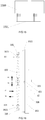
- FIG. 11 is a serial of side views illustrating the opening of the mounting structure for a display screen according to a second embodiment of the present invention, wherein FIG. 11 a shows a locked state, FIG. 11 b shows the process of opening, and FIG. 11 c shows an opened state.
- FIG. 12 is an enlarge view of the lower end of FIG. 11 b.
- FIG. 13 is a side view of the mounting structure for a display screen in an exploded state according to a third embodiment of the present invention.
- FIG. 14 is a front view of the panel in the third embodiment of the present invention.
- FIG. 15 is a schematic structural view of the connection of data cables of display units in the third embodiment of the present invention.
- FIG. 16 is a side view of the panel of the mounting structure for a display screen according to a fourth embodiment of the present invention.
- FIG. 17 is a schematic structural view of the connection of a prior art cabinet and metal structure.
- FIG. 18 is a schematic structural view of the connection of data cables of display units in the prior art.
- FIG. 1 is a side view of a mounting structure for a display screen according to a first embodiment of the present invention.
- FIG. 2 is a perspective schematic structural view of an outer frame of a cabinet of the mounting structure for a display screen shown in FIG. 1 .
- FIG. 3 is a perspective schematic structural view of a panel of the mounting structure for a display screen shown in FIG. 1 .
- FIG. 4 is a schematic view of a lock mechanism of the mounting structure for a display screen shown in FIG. 1 in a locked state.
- FIG. 5 is a schematic view of the lock mechanism shown in FIG. 4 in an opened state.
- FIG. 6 is a schematic view of the key of the lock mechanism shown in FIG. 5 when pulled out.
- FIG. 7 is an exploded perspective schematic view of the lock mechanism shown in FIG. 4 .
- the mounting structure for a display screen of the present invention is used to mount a display screen, especially an LED display screen, to a fixed structure including but not limited to a wall, a civil structure and a metal structure.
- the mounting structure for a display screen according to the first embodiment of the present invention comprises, at one side, a cabinet 100 for fixing a display screen 190 , wherein the cabinet 100 includes an outer frame 101 that is connected to the fixed structure (not shown) and a panel 102 that is detachably connected to the outer frame 101 , and the display screen 190 is provided outside of the panel 102 .
- the connection between the display screen 190 and the panel 102 is the same as that in the prior art and thus is omitted.
- one panel corresponds to one outer frame. It may also be conceived that one panel corresponds to a plurality of outer frames, that is, one panel is mounted after the plurality of outer frames are combined.
- the first embodiment of the present invention will be understood with reference to FIGS. 1-7 .
- the lower end of the outer frame 101 is provided with a V-shaped groove 103 having an opening facing upwards, and the opposite upper end is provided with a transverse locking rod 104 .
- the lower end, here referring to the position in FIG. 3 of the panel 102 at a side connecting with the outer frame 101 is provided with a V-shaped hook 105 having an opening facing downwards.
- a plane in which the V-shaped hook 105 lies is perpendicular to a plane in which the V-shaped groove 103 is lies, and the V-shaped hook 105 and the V-shaped groove 103 are snapped perpendicular to each other, facilitating the positioning therebetween.
- the bottoms of the V-shaped hook 105 and of the V-shaped groove 103 should be set as a small U-shape respectively in order to facilitate the snapping therebetween.
- This embodiment adopts such a structure that the V-shaped hook 105 and the V-shaped groove 103 are snapped together, because after the V-shaped hook 105 is placed on the V-shaped groove 103 , the panel 102 can be rotatable around the V-shaped groove 103 in a direction toward or away from the outer frame 101 so that a rotatable snap connection is formed, facilitating the installation and removal.
- the upper end, herein referring to the position in FIG. 3 , of the panel 102 at the side connecting with the outer frame 101 is provided with a locking box 110 .
- the locking box 110 functions to lock the panel 102 and the outer frame 101 together by locking the locking rod 104 so as to form a complete cabinet when the panel 102 is connected to the outer frame 101 , and functions to, upon maintenance, facilitate the unlocking and detaching the panel 102 from the outer frame 101 easily.
- the locking box 110 There are many specific configurations of the locking box 110 , as long as it is capable of locking so as to fixedly connect the panel 102 to the outer frame 101 in use, and is capable of unlocking so as to easily detach the panel 102 from the outer frame 101 in case of removal or maintenance.
- the locking box 110 shown in FIGS. 4 to 7 is used.
- the locking box 110 comprises a lock shell 111 and an interlock means that is located inside the lock shell 111 , wherein a slide channel 112 is opened at the lock shell 111 which in the present embodiment is formed by two locking panels 2 fixedly connected to each other, and the locking rod 104 can enter or exit from the slide channel.
- the interlock means comprises a latch 120 and a locking hook 130 for locking the latch 120 .
- An end of the latch 120 is rotatably connected to the first rotation shaft 126 fixed to the lock shell, and is provided with a first return spring 121 .
- the other end of the latch 120 includes a first tongue 1201 and an opposite second tongue 1202 so as to form a U-shaped opening 1200 for retaining the locking rod 104 entering the slide channel 112 .
- the first return spring 121 makes the U-shaped opening 1200 intersect with the slide channel 112 , forming a state in which the lower ends of the first and second tongues 1201 and 1202 forming the U-shaped opening 1200 respectively coincide with the two edges of the slide channel 112 so as to receive the locking rod 104 entering the slide channel 112 .
- One tongue in FIG. 4 in the locked state retaining the locking hook 130 is designated as the second tongue 1202 , and the other is called as the first tongue 1201 .
- the outer side of the first tongue 1201 with respect to the U-shaped opening 1200 is a rounded shape, and the outer side of the second tongue 1202 is a flat shape.
- One end of the locking hook 130 is a connecting portion that is rotatably connected to the second rotation shaft 136 fixed on the lock shell 111 and that is provided with a second return spring 131 .
- a hook portion 1301 provided at the other end of the locking hook 130 contacts the outer side of the second tongue 1202 to form a shape that prevents the latch 120 , which under the action of the first return spring 121 has a tendency to rotate clockwise, from rotating clockwise, and the hook portion 1301 interacts with the outer side of the second tongue 1202 so as to form the interlock means between the latch 120 and the locking hook 130 .
- the locking hook 130 In the locked state, the locking hook 130 has a tendency to rotate clockwise under the action of the second return spring 131 , and the second tongue 1202 have a tendency to rotate clockwise under the action of the first return spring, so that the outer side of the second tongue 1202 interacts with the hook portion 1301 so as to make both of them in an equilibrium state.
- it is needed to rotate the locking hook 130 counterclockwise to reach a position shown in FIG. 5 . As shown in FIG.
- the locking hook 130 in case of opening, is rotated counterclockwise under the action of external force so that the hook portion 1301 is disengaged from the second tongue 1202 , the latch 120 under the action of the first return spring is rotated clockwise back to the position at which the first tongue 1201 and the second tongue 1202 coincide with the two edges of the slide channel 112 respectively, and the lock shell 111 is translated so as to make the locking rod 104 out of the slide channel 112 , whereby achieving the unlocking.
- the locking hook 130 under the action of the second return spring 131 returns back to its equilibrium position which may be at or below the slide channel 112 , as long as the length of the second tongue 1202 can be retained mutually by the hook portion 1301 of the locking hook 130 .
- the outer side of the first tongue 1201 , the inner side of the second tongue 1202 , and the outer side of the hook portion 1301 are all in a smoothly arc shape, such that when the outer side of the hook portion 1301 contacts the outer side of first tongue 1201 or the inner side of the second tongue 1202 , they can slide relative to each other rather than being stuck.
- FIGS. 3 and 4 The working status when the locking box 110 of the present embodiment is locked will be understood with reference to FIGS. 3 and 4 .
- the locking rod 104 is retained by the latch 120 which in turn is locked by the locking hook 130 , reaching an equilibrium state, so that the upper end of the panel 102 having installed the locking box 110 thereon is firmly connected to the upper end of the outer frame 101 provided with the locking rod 104 , and since the lower ends of the panel 102 and of the outer frame 101 have formed a fixed connection through the mutually snapped V-shaped groove structures, the panel 102 and the outer frame 101 are fixedly connected to each other.
- the V-shaped hook 105 at the lower end of the panel 102 is placed on the V-shaped groove 103 at the lower end of the outer frame 101 to make them mutually snapped, and then the panel 102 is capable of rotating relative to the outer frame 101 .
- the panel 102 is rotated toward the outer frame 101 , and the locking rod 104 at the upper end of the outer frame 101 enters the slide channel 112 of the locking box 110 at the upper end of the panel 102 .
- the locking rod 104 contacts the first tongue to rotate the first tongue and second tongue counterclockwise.
- the outer side of hook portion 1301 , the outer side of the first tongue 1201 and the inner side of the second tongue 1202 are smoothly arc-shaped, they slide relative to each other in case of contact, until the inner side of the hook portion 1301 of the locking hook 130 is mutually retained by the outer side of the second tongue 1202 , under the action of the respective return spring, so as to form a locked structure.
- the locking hook 130 is rotated counterclockwise by an external force so as to disengage the hook portion 1301 from the second tongue 1202 , and then the panel 102 is rotated away from the outer frame 101 , and then the locking rod 104 contacts the second tongue to push the latch 120 to rotate clockwise.
- the latch 120 reaches a position shown in FIG. 5 , due to lack of the blocking from the hook portion 1301 .
- the panel 102 is continued to rotate, and the locking rod 104 will exit from the lock shell 111 , thus achieving the unlocking of the panel 102 from the outer frame 101 .
- the panel 102 can be separated from the outer frame 101 .
- an elastic pad 170 is further provided.
- the elastic pad 170 abuts against the outer side of the first tongue 1201 of the latch 120 in the locked state, giving an elastic force to rotate the latch 120 clockwise so as to make the latch 120 in a more stable state.
- a key 180 is used to rotate the locking hook 130 counterclockwise.
- the key 180 includes a key rod 1801 , a taper head 1802 which is located at the leading end of the key rod 1801 , and a boss 1803 adjacent the head 1802 that protrudes from the key rod 1801 such that a step is formed between the boss 1803 and the key rod 1801 , and an operating handle 1804 is at the trailing end of the key rod 1801 .
- a lockhole is provided on the lock shell 111 such that the key 180 after insertion can contact the connecting portion of the locking hook 130 .
- a projecting ratchet 1303 having a radial retaining surface 1302 is provided on the connecting portion of the locking hook 130 .
- the outer side of the ratchet 1303 has a smooth arc surface 1303 that is connected at the top with the radial retaining surface 1302 .
- the hook portion 1301 of the locking hook 130 may be provided with a rope leading to the outside of the cabinet, which can be pulled to rotate the locking hook 130 counterclockwise so as to achieve the unlocking.
- the locking hook 130 is made of magnetic material including e.g., iron, steel, nickel, and a magnet is placed outside of the lock shell 111 to rotate the locking hook 130 counterclockwise so as to achieve the unlocking.
- an anti-drop structure for preventing the key 180 from dropping is further provided, which includes a chuck 160 particular to the key 180 .
- the outer end of the chuck 160 is exposed outside of the locking box 110 and is provided with a chuck handle 1601 .
- a surface at the inner end of the chuck 160 facing the direction of the keyhole is a slope surface, and the opposite surface is a flat surface.
- the chuck 160 is wound with a chuck spring 1605 for returning.
- the chuck spring 1605 extends the chuck 160 so that the flat surface of the chuck 160 abuts against the boss 1803 of the key 180 , thus preventing the key 180 from exiting outwards.
- the chuck handle 1601 when it is need to withdraw the key, the chuck handle 1601 is pulled so as to make the chuck out of being retained and thus to withdraw the key.
- the reason why the surface at the inner end of the chuck 160 facing the direction of the keyhole is the slope surface is that, when the key 180 enters the interlock means shown in FIG. 4 in the locked state, the chuck 160 will not impede the key 180 , and the chuck 160 under the action of the tapered head 1802 of the key 180 is moved downward to compress the chuck spring 1605 so that the key 180 can successfully enter.
- the boss 1803 of the key 180 and the ratchet are mutually retained, under the action of the chuck spring 1605 , the chuck 160 is also restored and retained by the boss 1803 of the key 180 , preventing the key 180 from dropping automatically.
- the outer frame 101 and the panel 102 of the cabinet 100 have a detachable connection, and both of them in the connected state can achieve the locking. Since the accurate positioning between the outer frame 101 and the panel 102 can be achieved through mutually retaining structures of the V-shaped groove and the V-shaped hook on the lower portion thereof, the mounting accuracy of the entire cabinet and also of the display screen can be ensured, as long as the mounting accuracy between the outer frames 101 is ensured. Therefore, in order to achieve precise positioning and installation, the outer frame 101 in the present invention is precisely positioned so as to achieve precise installation.
- FIG. 8 is a schematic view illustrating the first mounting manner of the outer frame of the cabinet of the mounting structure for a display screen according to the first embodiment of the present invention.
- the sides of adjacent two outer frames that are connected to each other are respectively provided with a first positioning pin 8012 and a corresponding first positioning hole 8013 for accurate positioning, and a corresponding connection bolt 8110 is used for connecting the adjacent outer frames.
- the major focus is to accurately position and install the first outer frame 801 , and the other outer frames 802 can be positioned relative to the first outer frame through the first positioning pin and its corresponding first positioning hole, whereby achieving the accurate positioning of all the outer frames.
- the panel is then mounted and thus also has an accurate positioning and convenient installation, and there is no need to adjust the positioning after the installation.
- the numbers of the first positioning pin and the first positioning hole are not limited, and in the case of having a plurality of the first positioning pins and the first positioning holes, they are preferably in the form of asymmetric distribution.
- the first positioning pin and the first positioning hole may also be replaced by a combination of a positioning rib and a positioning groove. Compared with a manner of installing the cabinet as a whole, it has lightweight and is easier to install, because it is only need to install the outer frames while the positioning is carried out.
- FIG. 9 is a schematic view illustrating the second mounting manner of the outer frame of the cabinet of the mounting structure for a display screen according to the first embodiment of the present invention.
- the first outer frame 901 is provided with a first positioning column 9011 and a second positioning column 9012
- the second outer frame 902 is provided with a third positioning column 9023 and a fourth positioning column 9024 .
- a mounting fixture 905 is made according to a design distance between the positioning columns on the first outer frame 901 and the adjacent second outer frame 902 .
- Four corners of the mounting fixture 905 are provided with a first positioning hole 9051 , a second positioning hole 9052 , a third positioning hole 9053 and a fourth positioning hole 9054 , respectively.
- a distance between the first positioning hole 9051 and the second positioning hole 9052 is equal to a distance between the first positioning column 9011 and the second positioning column 9012
- a distance between the third positioning hole 9053 and the fourth positioning hole 9054 is equal to a distance between the third positioning column 9023 and the fourth positioning column 9024 .
- a distance between the first positioning hole 9051 and the third positioning hole 9053 is determined by a distance between the first positioning column 9011 and the third positioning column 9023 respectively provided on the first outer frame 901 and the second outer frame 902 after being installed according to the design requirement.
- a distance between the second positioning hole 9052 and the fourth positioning hole 9054 is also determined by a design distance between the second positioning column 9012 and the fourth positioning column 9024 .
- the distance between the positioning holes of the mounting fixture 905 in the up and down direction is determined by the distance between the positioning columns on the outer frame, while the distance between the positioning holes in the horizontal direction is equal to the distance between the positioning columns on the adjacent outer frames that meet the design requirements.
- a rectangular structure consisting of the outer frames has a shape and position with high accuracy. Based on this, the panel is then mounted and thus also has an accurate positioning and convenient installation, and there is no need to adjust the positioning after the installation.
- FIG. 10 is a schematic structural view of a bayonet of a mask and the panel of the mounting structure for a display screen according to the first embodiment.
- a mask 1002 is connected to the display unit 1001 by a bayonet.
- the mask 1002 and the display unit 1001 are respectively provided with a first bayonet 1012 and a second bayonet 1022 , both of which are elastic and have slope surfaces that are against each other during the installation and flat surfaces that are mutually retained each other in the snapped state.
- the mask 1002 is connected to the display unit 100 by a bayonet structure that may be unlocked by contacting slightly during maintenance so as to detach the panel and thus to repair and change a damaged part, which process can be done quickly with no tool and without any damage.
- This embodiment has many advantages as follows.
- a matrix is formed by the connection of the outer frames, and each panel corresponds to one or more outer frames. There is no force between the panels mounted on the outer frame, the advantage of which is that the panel can be removed from the front, and it is possible to only remove a damaged panel in any position.
- the outer frames have the same structure and can be positioned relative to each other, the panel installed after the outer frame can automatically meet the requirements of the cabinet gap and flatness, thus saving installation time.
- the panel is rotatable about a point where the two V shapes intersect as a rotation axis, so that the panel may be removed either from the front or from the back, facilitating the installation, removal and maintenance.
- the lock mechanism Since the upper ends of the outer frame and of the panel are fixedly connected by the lock mechanism, the installation and disassembly of the cabinet can be done from the front by hand without a tool.
- the lock mechanism can be unlocked rapidly by two ways of a non-contact manner (by means of magnet attracting) and a contact manner (by means of the key) so as to separate the panel from the outer frame of the cabinet, and at the same time the power supply is automatically decoupled with the data.
- the outer frame is preferably made of aluminum alloy with good heat dissipation performance, and the panel will be provided on the outer frame so as to form the overall heat dissipating system, increasing the heat dissipating area, improving the reliability and reducing the failure rate.
- FIG. 11 is a serial of side views illustrating the opening of the mounting structure for a display screen according to a second embodiment of the present invention, wherein FIG. 11 a shows a locked state, FIG. 11 b shows the process of opening, and FIG. 11 c shows an opened state.
- FIG. 12 is an enlarge view of the lower end of FIG. 11 b.
- the panel 202 and the outer frame 201 in the second embodiment have similar structures to those in the first embodiment respectively.
- the differences therebetween are that, as shown in FIGS. 11 and 12 , the inner side of the lower end surface of the outer frame 201 has an upwardly bent side edge having a horizontal positioning hole 2014 therein, so that a V-shaped groove is formed between it and the lower end surface.
- the lower end of the panel 202 is provided with a V-shaped hook 2021 .
- the V-shaped hook 2021 in the second embodiment differs from the V-shaped hook of the first embodiment in that, the side of the V-shaped hook 2021 snapped with the outer frame 201 is located in the vertical direction in the locked state, that is in close contact with the side edge of the panel 202 , and is provide with a positioning column 2024 corresponding to the positioning hole 2014 .
- the panel 202 and the outer frame 201 are positioned through the cooperation of the positioning column 2024 and the positioning hole 2014 , and are snapped together when the panel 202 is inclined to the outer frame 201 , at this time a portion of the lower end of the panel 202 being in contact with the outer frame 201 too.
- the above structure is relatively simple and can achieve a quick connection and removal.
- the edge of the V-shaped hook snapped with the V-shaped groove can be set as a straight edge (i.e. in the locked state in the vertical direction), or can be set as a sloping edge, but the straight edge facilitates the easier positioning therebetween.
- the upper ends of the panel 202 and of the outer frame 201 may still be fixedly connection by the lock mechanism, such as the lock mechanism 110 A in the first embodiment.
- the lock mechanism 110 A in the first embodiment.
- FIG. 11 another form of the lock mechanism is adopted in the second embodiment.
- the lock mechanism in the second embodiment comprises a locking rod 204 that is fixedly connected to the outer frame 201 via a bracket.
- the interlock structure includes a latch 21 and a slider block 22 that are rotatably connected to the panel 202 and that are respectively provided with a corresponding return spring (not shown in the drawings).
- the latch 21 has a similar structure and function to those of the latch 120 in the first embodiment.
- the slider block 22 has a similar structure and function to those of the locking hook 130 in the first embodiment, except that the whole slider block 22 or at least an end of the slider block 22 that is not provided with the hook portion, namely an end opposite to the end provided with the hook portion, is made of magnetic material such as iron or steel, and when unlocking, a magnet is placed outside of the panel 202 to attract the slider block 22 to rotate so as to achieve the unlocking.
- the panel 202 is pressed down in the direction of the arrow C 1 and then is rotated so as to make the upper lock mechanism locked.
- the lock mechanism is unlocked at first, and then the upper end of the panel 202 is rotated away from the outer frame 201 , and then the panel 202 is lifted obliquely upwards in the direction of the arrow C 2 so as to be separated from the outer frame 201 .
- the upper end of the outer frame 201 has a respective socket 241 that may be a data outlet or a power outlet, and although not shown, the upper end of the panel 202 has a corresponding plug to achieve an electrical connection with the socket 241 .
- the socket and the plug may have an opposite magnet respectively, and the magnets attract each other, thereby improving the reliability of the connection thereof.
- first and second embodiments lie in that, firstly, the rotatable connection between the lower ends of the outer frame and of the panel is slightly different; secondly, the specific structure of the lock mechanism adopted at the upper ends of the outer frame and of the panel is different. Both of them have similar effects, but the second embodiment is more convenient and simpler due to the use of a non-contact unlocking manner.
- the outer frame in the present embodiment can be mounted in a similar manner to that in the first embodiment. That is to say, it can be positioned exactly by providing corresponding positioning members at the four sides of the outer frame, or by providing the positioning holes in the outer frame, that is, by positioning the adjacent outer frames using the mounting fixture having positioning pins, the dimension between which is determined according to design requirements.
- FIG. 13 is a side view of the mounting structure for a display screen in an exploded state according to a third embodiment of the present invention.
- FIG. 14 is a front view of the outer frame of the mounting structure for a display screen according to the third embodiment of the present invention.
- the panel 302 during disassembly or installation is moved into and out of the outer frame 301 in parallel thereto, and the side of the outer frame 301 and the opposite side of the panel 302 are fixedly connected to each other by the lock mechanism. Since the panel 302 is moved into and out of the outer frame 301 in parallel thereto, in order to achieve the accurate positioning, the side of the outer frame 301 facing the panel 302 is provided with one or more positioning holes 3011 that are preferably distributed in an asymmetric manner for better positioning. A plurality of corresponding positioning columns or pins 3021 are provided on the panel 302 .
- the lock mechanism comprises a lockhole 304 that is respectively provided in the upper end and the lower end of the outer frame in the vertical direction, and a tongue that is provided at the inner side of the panel and is movable in the up and down direction.
- the tongue and the side of the lockhole in contact with the tongue 305 are smoothly curved respectively, and in the opened state as shown in FIG.
- the tongue 305 under the action of the return spring is in the extended position, and when the tongue 305 enters the lockhole 304 , the tongue 305 under the action of the return spring is also in the extended position, so that the tongue 305 is located in the lockhole 304 and the panel 302 is fixedly connected to the outer frame 301 , that is, the lock mechanism is in a locked state.
- the installation may be understood with reference to FIG. 13 .
- the end of the tongue 305 and the front end of the lockhole 304 abut against each other so as to press the tongue 305 to be retracted in the direction of arrow B 2 , and when the tongue 305 reaches the position of the lockhole 304 , the tongue 305 under the action of the return spring 3051 is pressed to extend along the direction of arrow B 1 into the lockhole 304 to form a retaining state with the lockhole.
- the power plug 3027 or the date plug 3028 within the panel 302 is connected to the power socket 3017 or the data socket 3018 provided on the base end of the outer frame 301 respectively, and the display screen 308 after being powered on displays the related information.
- a first spring 3117 is provided between the power socket 3017 and the outer frame 301
- a second spring 3118 is provided between the data socket 3018 and the outer frame 301 , and the force of the first spring 3117 and the second spring 3118 makes more reliable connection between the socket and the plug.
- the tongue 305 is forced by external force to retract in the direction of arrow B 2 and then the panel 302 is translated in the direction of arrow D 2 , and when the panel 302 is moved out of the outer frame 301 , the external force is withdrawn and the tongue 305 can be restored in the direction of the arrow B 1 under the action of the return spring to a position as shown in FIG. 13 .
- the external force can be obtained by a toggle lever provided on the panel 302 , which drives the tongue 305 to move up and down against the elastic force of the return spring and thus exit from the lockhole 304 .
- any other structure may be provided.
- the tongue 305 is made of magnetic material, and an electromagnet is provided at the other end of the tongue 305 to attract the tongue 305 to move up and down, wherein when the electromagnet is energized, the tongue 305 is retracted by the attraction between the electromagnet and the tongue 305 , and when the electromagnet is de-energized, the tongue is restored under the action of the return spring.
- a structure that enables the tongue 305 to move up and down can achieve the purpose of the present invention.
- FIG. 13 when a magnet 321 is used to contact the respective position of the panel, the slide block 331 under the action of the magnet is moved rightwards in the figure and compresses the spring 3310 . As the slide block 331 moves rightwards, the return spring 3051 makes the tongue 305 move out of the lockhole 304 , and thus the unlocking is achieved.
- the base of outer frame 301 is provided with an unlocking spring 3014 .
- the unlocking spring 3014 is in a compressed state subject to an external force, and when the tongue 305 is retracted from the lockhole 304 , the unlocking spring 3014 automatically pop the panel 302 out, and it is apparent that the spring force of the unlocking spring 3014 should not be too large.
- the outer frame 301 may be in a regular shape, preferably rectangular, hexagonal, triangular, and the most preferably rectangular.
- the outer frame 301 includes one or more stiffening ribs to strengthen the outer frame so as to be not easily deformed.
- Each side of the outer frame 301 has one or more positioning pins for precise positioning.
- Each side of the outer frame 301 has one or more fixing bolts for fixing the outer frame to the other outer frames, or fixing the outer frame to a bracket or a building surface.
- the outer frame 301 is generally made of steel. As shown in FIG. 14 , in this embodiment, the four corners of the panel 302 are respectively embedded with an electromagnet 3024 , and when the power plug is connected to the power socket, the power source is turned on by the electromagnets which are tightly adsorbed on the outer frame 301 ; and so on, the panel 302 of each cabinet is tightly adsorbed on the corresponding outer frame 301 of the cabinet, ensuring the flatness of the cabinet panels.
- the installation process can be performed by any non-professional person with no tool.
- the outer frame 301 in the present embodiment can be mounted in a similar manner to that in the first embodiment. That is to say, it can be positioned exactly by providing corresponding positioning members at the four sides of the outer frame, or by providing the positioning holes 3011 in the outer frame 301 , that is, by positioning the adjacent outer frames using the mounting fixture having positioning pins, the dimension between which is determined according to design requirements.
- the present embodiment has advantage of easier and more convenient installation and disassembly. There is only one action of pushing the panel into the outer frame during installation, and only two actions are needed to detach the panel during maintenance. Installation and disassembly of the panel can be completed with no tool.
- a prior art HUB plate and a control card are integrated into a PCB board 1501 , which reduces the number of 40-pin plugs for connecting the HUB and the control card.
- the display unit 1500 is welded to the PCB board 1501 having integrated the functions of the control card and HUB plate, which further reduces the number of the plugs. Meanwhile, the display units 1500 are all connected to the PCB board 1501 through data connection, while there is no data connection between the display units 1500 , which reduces the number of the 100-pin plugs.
- the display unit and the power source also have a welded connection therebetween, which reduces the number of 8-pin plugs.
- the number of data plugs and power plugs of the cabinet is greatly reduced, facilitating the installation and removal.
- data connection may be either contact connection or non-contact connection.
- the socket and the plug may have a direct contact connection through the pin needles, or have a non-contact wireless connection via Bluetooth, WIFI, infrared, magnetic sensors, etc.
- the socket and the plug respectively have a built-in magnet, and the magnets tightly attract when the socket and the plug are close so as to improve the reliability of the data connection.
- a hollow space is formed between the panel 302 and the outer frame 301 of the cabinet, facilitating the heat dissipation.
- the outer frame 301 is preferably made of aluminum alloy material with good heat dissipation performance, and the power lock shell, the cabinet and the cabinet outer frame constitute the overall aluminum alloy heat dissipating system.
- detaching the panel can be done from the front, and the front installation and maintenance can be operated by non-professionals.
- the installation or maintenance of the cabinet can be completed quickly by only two actions.
- FIG. 16 is a side view of the panel of the mounting structure for a display screen according to a fourth embodiment of the present invention.
- the outer frame of the mounting structure for a display screen in the fourth embodiment has the same configuration as that in the third embodiment, and the panel has the substantial same configuration as that in the third embodiment, the difference mainly lies in a different structure for extending or retracting the tongue.
- a hinge 400 of parallelogram having a pivot point at each of its four vertexes is adopted to achieve the extension and retraction of the tongue.
- the other end of the return spring 3051 of each tongue 305 is provided with one first slider block 411 .
- the upper vertex and lower vertex of the parallelogram are respectively provided with the first slider block 411 , the left vertex of the parallelogram is fixed to the base surface of the outer frame, and the right vertex thereof is provided on a horizontal slider block 42 that is horizontally movable and that is provided on the back of the panel 402 .
- the horizontal slider block 42 is made of magnetic material, and apparently a return spring 421 is provided between the horizontal slider block 42 and the panel 302 . Referring to FIGS.
- the panel 302 is pushed towards the outer frame 301 in parallel thereon along the direction of arrow Z 4 .
- the tongues 305 compress the upper and lower first slider blocks 411 through the return springs 3051 respectively such that a distance between the upper and lower vertexes becomes small, that is, the upper vertex moving along arrow Z 5 direction and the lower vertex along arrow Z 6 direction, and the tongues 305 are retracted.
- the tongues 305 when the tongues 305 are aligned with the lockholes 304 respectively, the tongues 305 under the action of the return springs 3051 are deeply inserted into the lockholes 304 respectively so as to drive the upper and lower vertexes to move in the opposite directions, that is, the upper vertex moving along arrow Z 1 direction and the lower vertex along arrow Z 2 direction, and the hinge 400 urges a distance between the left and right vertexes to be small, and at this time the tongue 305 is located within the respective lockhole 304 in a locked state.
- a magnet or electromagnet is placed outside of the display screen 480 to attract the horizontal slider block to displace horizontally toward the panel, that is to move in the direction of the arrow Z 3 of FIG. 16 , so that the distance between the left and right vertexes increases, and the distance between the upper and lower vertexes also increases due to the pulling of the hinge, the upper vertex moving along arrow Z 5 direction and the lower vertex along arrow Z 6 direction, thereby the upper and lower tongues 305 being retracted and exiting from the lockhole 304 , and then the panel 302 can be translated outwards and removed.
- the magnet is removed, and the horizontal slider block 42 under the action of the return spring 421 is translated towards the direction away from the panel 302 , so that the distance between the left and right vertexes decreases, and the upper and lower vertexes are pushed by the hinge 400 such that the distance therebetween increases, and therefore the tongue 305 is restored.
- the structure in the fourth embodiment is simpler, in which the parallelogram hinge 400 is used to make the tongue 305 in and out of the lockhole 304 , whereby enabling easy and quick installation or removal of the panel.
Landscapes
- Engineering & Computer Science (AREA)
- General Engineering & Computer Science (AREA)
- Mechanical Engineering (AREA)
- Microelectronics & Electronic Packaging (AREA)
- Devices For Indicating Variable Information By Combining Individual Elements (AREA)
- Physics & Mathematics (AREA)
- General Physics & Mathematics (AREA)
- Theoretical Computer Science (AREA)
- Casings For Electric Apparatus (AREA)
Abstract
Description
Claims (4)
Applications Claiming Priority (7)
| Application Number | Priority Date | Filing Date | Title |
|---|---|---|---|
| CN201410158651.3 | 2014-04-21 | ||
| CN201410158651 | 2014-04-21 | ||
| CN201410158651 | 2014-04-21 | ||
| CN201520231095.8 | 2015-04-17 | ||
| CN201520231095.8U CN205104166U (en) | 2014-04-21 | 2015-04-17 | Display screen mounting structure of area lock box |
| CN201520231095U | 2015-04-17 | ||
| PCT/CN2015/076942 WO2015161761A1 (en) | 2014-04-21 | 2015-04-20 | An assemble structure for a display screen |
Publications (2)
| Publication Number | Publication Date |
|---|---|
| US20160255731A1 US20160255731A1 (en) | 2016-09-01 |
| US10537032B2 true US10537032B2 (en) | 2020-01-14 |
Family
ID=54331740
Family Applications (1)
| Application Number | Title | Priority Date | Filing Date |
|---|---|---|---|
| US15/028,397 Active 2037-01-07 US10537032B2 (en) | 2014-04-21 | 2015-04-20 | Mounting structure for display screen |
Country Status (3)
| Country | Link |
|---|---|
| US (1) | US10537032B2 (en) |
| CN (1) | CN205104166U (en) |
| WO (1) | WO2015161761A1 (en) |
Cited By (3)
| Publication number | Priority date | Publication date | Assignee | Title |
|---|---|---|---|---|
| US11183087B1 (en) | 2020-04-30 | 2021-11-23 | Draper, Inc. | Support system for modular display system |
| US11477897B2 (en) * | 2020-03-02 | 2022-10-18 | Shenzhen Absen Optoelectronic Co., Ltd. | Support frame and LED display screen system including such support frame |
| USD974877S1 (en) | 2020-04-30 | 2023-01-10 | Draper, Inc. | Electronic display mount |
Families Citing this family (63)
| Publication number | Priority date | Publication date | Assignee | Title |
|---|---|---|---|---|
| CN106463083B (en) * | 2014-12-29 | 2020-02-18 | 平面系统公司 | Mounts with concealed magnetically actuated positioning |
| KR101898706B1 (en) * | 2017-07-31 | 2018-09-13 | 엘지디스플레이 주식회사 | Mounting apparatus and assembly apparatus for display module and method of same |
| CN107426636B (en) * | 2017-07-31 | 2023-09-01 | 歌尔智能科技有限公司 | Quick installing support and mounting structure of stereo set |
| CN107591094B (en) * | 2017-09-08 | 2019-09-27 | 庄黎玲 | A kind of LED display external member |
| CN107808607B (en) * | 2017-11-28 | 2024-03-26 | 合肥惠科金扬科技有限公司 | Front display module assembly self-locking device and front maintenance type display equipment |
| CN108010453B (en) * | 2018-01-16 | 2024-04-12 | 深圳市彩易达光电有限公司 | LED display screen front maintenance tool |
| CN108628494B (en) * | 2018-04-09 | 2024-07-16 | 江苏聚泰科技有限公司 | Shock-resistant structure for touch screen |
| CN108506881B (en) * | 2018-05-10 | 2023-09-12 | 福建吉艾普光影科技有限公司 | Multifunctional stroboscopic lamp |
| CN108533926A (en) * | 2018-05-23 | 2018-09-14 | 北京小米移动软件有限公司 | Hanging structure and electronic equipment |
| CN108662373A (en) * | 2018-06-27 | 2018-10-16 | 贵州大学 | A kind of computer screen holder with elevating function |
| CN108665802B (en) * | 2018-06-29 | 2023-12-26 | 深圳利亚德光电有限公司 | Locking mechanism and display screen with same |
| KR102073396B1 (en) * | 2018-08-24 | 2020-02-04 | 삼성전자주식회사 | Display appartus |
| WO2020055988A1 (en) * | 2018-09-11 | 2020-03-19 | Daktronics, Inc. | Magnetically-actuated latch mechanism for display module |
| CN109185286A (en) * | 2018-10-29 | 2019-01-11 | 深圳市格特隆光电股份有限公司 | A kind of lever LED display cabinet locked mechanism |
| CN108999849B (en) * | 2018-10-29 | 2023-12-26 | 湖南明和光电设备有限公司 | An eccentric rotating connector and LED display box |
| CN109377897B (en) * | 2018-12-13 | 2020-08-28 | 杭州显迈科技有限公司 | An installation device for an LED display |
| CN109611673B (en) * | 2018-12-25 | 2025-03-14 | 建浩支架(昆山)有限公司 | Pull cord to unlock the bracket |
| US11047155B2 (en) | 2018-12-26 | 2021-06-29 | Nanning Fugui Precision Industrial Co., Ltd. | Concealed anti-tamper device |
| US11191178B2 (en) | 2019-01-24 | 2021-11-30 | Steelcase Inc. | Display support system and method for the use thereof |
| CN109931317B (en) * | 2019-03-05 | 2024-10-18 | 深圳市光祥科技股份有限公司 | Tighten the lock and the LED display cabinet |
| CN110213930A (en) * | 2019-07-04 | 2019-09-06 | 网来(浙江)科技有限公司 | The mounting structure of controller |
| CN110189641A (en) * | 2019-07-04 | 2019-08-30 | 深圳市齐普光电子股份有限公司 | A LED display screen that is easy to install and disassemble |
| CN110415621B (en) * | 2019-09-02 | 2024-06-18 | 深圳市迈锐光电有限公司 | LED display screen module maintenance mechanism |
| CN110740602A (en) * | 2019-11-18 | 2020-01-31 | 湖南新亚胜光电股份有限公司 | Power Box Fixtures and Displays |
| CN111063272B (en) * | 2020-01-07 | 2024-10-01 | 深圳市奥拓电子股份有限公司 | LED unit box and LED display screen |
| CN111645015B (en) * | 2020-06-28 | 2025-03-18 | 南京埃斯顿自动化股份有限公司 | Back plate structure for quick installation and disassembly |
| CN111857419B (en) * | 2020-07-14 | 2022-09-20 | 北海翰博士科技有限公司 | A touch screen with an anti-fall protection mechanism |
| CN115918281A (en) | 2020-07-23 | 2023-04-04 | 斯蒂尔凯斯有限公司 | Monitor Mount System and How to Use It |
| CN111724694B (en) * | 2020-07-30 | 2024-08-16 | 利亚德智慧显示(深圳)有限公司 | Display |
| US11317529B2 (en) * | 2020-08-21 | 2022-04-26 | Quanta Computer Inc. | SSD carrier bracket |
| US20220108638A1 (en) * | 2020-10-02 | 2022-04-07 | Planar Systems, Inc. | Led module positioning system |
| CN114370563B (en) * | 2020-10-15 | 2024-08-09 | 华硕电脑股份有限公司 | Screen Fixing Device |
| CN112285409B (en) * | 2020-11-25 | 2024-06-28 | 慈溪市质量技术监督检验检测服务中心 | A portable electrostatic voltmeter detection device |
| CN112664803A (en) * | 2020-12-16 | 2021-04-16 | 江西超弦光电科技有限公司 | LED display screen unit board connecting device |
| CN213716389U (en) * | 2020-12-21 | 2021-07-16 | 深圳市光祥科技股份有限公司 | LED display screen box |
| CN112788893B (en) * | 2021-01-06 | 2022-03-29 | 武汉光迅科技股份有限公司 | Unlocking device applied to movable disc |
| CN113126707B (en) * | 2021-03-12 | 2023-02-28 | 山东英信计算机技术有限公司 | Node interlocking server |
| CN113207253B (en) * | 2021-04-21 | 2022-05-17 | 重庆电子工程职业学院 | Intelligent detection device with heat dissipation function and used for Internet of things |
| CN113036520B (en) * | 2021-04-25 | 2025-10-28 | 利亚德光电股份有限公司 | LED box connection device and LED display device |
| CN113463799B (en) * | 2021-06-23 | 2022-09-20 | 深圳市奥蕾达科技有限公司 | Perforated aluminum plate curtain wall lamp strip display screen |
| CN113628552B (en) * | 2021-08-09 | 2025-01-24 | 深圳市耕创电子有限公司 | Front maintenance device, LED unit box and LED display |
| CN113669606B (en) * | 2021-08-23 | 2025-04-22 | 深圳市元亨光电股份有限公司 | Maintenance tool and outdoor display device |
| CN113597151B (en) * | 2021-09-02 | 2025-04-08 | 广东海悟科技有限公司 | Concatenation formula rack temperature control system |
| CN113888990B (en) * | 2021-09-07 | 2024-12-27 | 深圳利亚德光电有限公司 | Box tensioning mechanism and LED box assembly having the same |
| CN113819356B (en) * | 2021-09-17 | 2025-02-14 | 深圳市光祥科技股份有限公司 | Arc lock and splicing screen |
| CN114110344A (en) * | 2021-11-30 | 2022-03-01 | 南通安邦信息技术有限公司 | A screen display application connection device |
| CN114567980B (en) * | 2022-02-25 | 2023-07-14 | 苏州浪潮智能科技有限公司 | A linkage disassembly structure of safety panel |
| CN114489286B (en) * | 2022-03-31 | 2022-07-08 | 苏州浪潮智能科技有限公司 | Server case bolt-lock structure and server |
| CN114973942A (en) * | 2022-04-07 | 2022-08-30 | 惠州市科莱电子有限公司 | Foldable display screen convenient to use |
| CN115331571B (en) * | 2022-07-26 | 2024-06-14 | 深圳市荣丰显示有限公司 | Installation lock assembly structure and LED display screen |
| CN115299705B (en) * | 2022-08-23 | 2023-09-12 | 南京千万户电子科技有限责任公司 | Combined goods shelf |
| CN115384414B (en) * | 2022-09-26 | 2025-10-31 | 浙江长江汽车电子有限公司 | Ceiling screen with novel unlocking and locking structure for suspended ceiling |
| CN115674095B (en) * | 2022-11-01 | 2025-07-04 | 苏州赛智达智能科技有限公司 | A capping mechanism for pressing a spring pin into a tooling |
| CN115802666B (en) * | 2022-11-17 | 2026-01-27 | 深圳利亚德光电有限公司 | Box body assembly of LED display device and LED display device |
| CN116221590B (en) * | 2022-12-19 | 2026-03-17 | 上海真兰工业自动化仪表有限公司 | EVC volume correction instrument |
| US12232285B2 (en) * | 2023-02-21 | 2025-02-18 | Quanta Computer Inc. | Mounting assembly with nested brackets |
| CN116366752B (en) * | 2023-03-03 | 2023-12-15 | 恒界时代科技(深圳)有限公司 | Liquid crystal display module and assembly structure of adaptation thereof |
| CN116275823B (en) * | 2023-05-16 | 2023-08-15 | 深圳市东陆科技有限公司 | LED display module assembly welding position frock |
| CN116608901B (en) * | 2023-05-19 | 2024-05-03 | 武汉宏联电线电缆有限公司 | Power equipment monitor |
| CN116844425B (en) * | 2023-05-25 | 2024-07-05 | 宜宾市瑞益嘉科技有限公司 | LED display screen |
| EP4470868A1 (en) * | 2023-05-30 | 2024-12-04 | Siemens Mobility GmbH | Rail vehicle with vehicle component and fastening method |
| CN117479471B (en) * | 2023-12-27 | 2024-05-03 | 深圳利亚德光电有限公司 | LED display device capable of being maintained front and back |
| CN120656388A (en) * | 2025-08-19 | 2025-09-16 | 闽南理工学院 | Educational propaganda device |
Citations (9)
| Publication number | Priority date | Publication date | Assignee | Title |
|---|---|---|---|---|
| USD532290S1 (en) * | 2005-02-07 | 2006-11-21 | Mike David | Flat television wall mounting hardware with lockable bottom tilt positioning |
| CN101546503A (en) | 2009-05-06 | 2009-09-30 | 上海优安信息技术有限公司 | Adjustable liquid crystal-spliced display wall |
| US7641163B2 (en) * | 2005-10-21 | 2010-01-05 | Peerless Industries, Inc. | Tilt mounting system |
| CN201487519U (en) | 2009-08-19 | 2010-05-26 | 余姚市宇达实业有限公司 | Wall hanging frame of plat panel television |
| CN201810964U (en) | 2010-08-19 | 2011-04-27 | 赵芸详 | Television wall hanging device with self-locking structure |
| CN201868037U (en) | 2010-11-10 | 2011-06-15 | 深圳市愿景光电子有限公司 | Splicing display wall |
| CN203179426U (en) | 2013-03-21 | 2013-09-04 | 惠州雷曼光电科技有限公司 | LED display screen, installation rack and LED display system |
| US20130256244A1 (en) * | 2012-03-29 | 2013-10-03 | Chia-Cheng Chen | Locking device for a display mounting assembly |
| US20150382491A1 (en) * | 2013-12-10 | 2015-12-31 | Maoqing YE | A positioning and adjusting device of display |
-
2015
- 2015-04-17 CN CN201520231095.8U patent/CN205104166U/en not_active Expired - Fee Related
- 2015-04-20 WO PCT/CN2015/076942 patent/WO2015161761A1/en not_active Ceased
- 2015-04-20 US US15/028,397 patent/US10537032B2/en active Active
Patent Citations (9)
| Publication number | Priority date | Publication date | Assignee | Title |
|---|---|---|---|---|
| USD532290S1 (en) * | 2005-02-07 | 2006-11-21 | Mike David | Flat television wall mounting hardware with lockable bottom tilt positioning |
| US7641163B2 (en) * | 2005-10-21 | 2010-01-05 | Peerless Industries, Inc. | Tilt mounting system |
| CN101546503A (en) | 2009-05-06 | 2009-09-30 | 上海优安信息技术有限公司 | Adjustable liquid crystal-spliced display wall |
| CN201487519U (en) | 2009-08-19 | 2010-05-26 | 余姚市宇达实业有限公司 | Wall hanging frame of plat panel television |
| CN201810964U (en) | 2010-08-19 | 2011-04-27 | 赵芸详 | Television wall hanging device with self-locking structure |
| CN201868037U (en) | 2010-11-10 | 2011-06-15 | 深圳市愿景光电子有限公司 | Splicing display wall |
| US20130256244A1 (en) * | 2012-03-29 | 2013-10-03 | Chia-Cheng Chen | Locking device for a display mounting assembly |
| CN203179426U (en) | 2013-03-21 | 2013-09-04 | 惠州雷曼光电科技有限公司 | LED display screen, installation rack and LED display system |
| US20150382491A1 (en) * | 2013-12-10 | 2015-12-31 | Maoqing YE | A positioning and adjusting device of display |
Cited By (3)
| Publication number | Priority date | Publication date | Assignee | Title |
|---|---|---|---|---|
| US11477897B2 (en) * | 2020-03-02 | 2022-10-18 | Shenzhen Absen Optoelectronic Co., Ltd. | Support frame and LED display screen system including such support frame |
| US11183087B1 (en) | 2020-04-30 | 2021-11-23 | Draper, Inc. | Support system for modular display system |
| USD974877S1 (en) | 2020-04-30 | 2023-01-10 | Draper, Inc. | Electronic display mount |
Also Published As
| Publication number | Publication date |
|---|---|
| US20160255731A1 (en) | 2016-09-01 |
| WO2015161761A1 (en) | 2015-10-29 |
| CN205104166U (en) | 2016-03-23 |
Similar Documents
| Publication | Publication Date | Title |
|---|---|---|
| US10537032B2 (en) | Mounting structure for display screen | |
| CN205104165U (en) | Install display screen structure fast | |
| US10314181B2 (en) | Display screen assembly and display device having the same | |
| CN210691861U (en) | Multi-display system, video display device, and pull-out mechanism | |
| CN110706610A (en) | LED display screen box | |
| CN109751489B (en) | Display | |
| CN106973534B (en) | Front maintenance display screen with six-direction adjusting function and display device | |
| CN205406022U (en) | Front -maintained LED display screen | |
| KR20170000575A (en) | Display module, display device and methods for assembling or disassembling display module | |
| CN215861134U (en) | Hoisting lock and display screen | |
| CN107248381A (en) | A kind of LED screen splicing construction and LED screen | |
| CN210073193U (en) | LED display assembly | |
| WO2017080147A1 (en) | Wall-mounted device of display device and display device | |
| CN104214716A (en) | Lamp post rotating angle fixing device | |
| CN114937409A (en) | Splicing sheet, splicing assembly and spliced display screen | |
| CN107564425A (en) | It is a kind of can plane or curved surface assembling LED display unit | |
| WO2022126530A1 (en) | Display screen housing and display screen | |
| CN110017536A (en) | Air conditioner | |
| US20240230073A1 (en) | Lamp mounting structure and lamp | |
| CN103925569B (en) | A lamp body disassembly structure for a downlight | |
| CN210120735U (en) | A combined cabinet | |
| CN205487157U (en) | Show screen assembly and have its display device | |
| CN209948446U (en) | Novel power control box | |
| CN223884148U (en) | Emergency marker light with dustproof construction | |
| US20240240779A1 (en) | Lamp mounting structure and lamp |
Legal Events
| Date | Code | Title | Description |
|---|---|---|---|
| AS | Assignment |
Owner name: HUANG, MING, CHINA Free format text: ASSIGNMENT OF ASSIGNORS INTEREST;ASSIGNOR:RAN, QIJIE;REEL/FRAME:038399/0641 Effective date: 20160321 Owner name: RAN, QIJIE, CHINA Free format text: ASSIGNMENT OF ASSIGNORS INTEREST;ASSIGNOR:RAN, QIJIE;REEL/FRAME:038399/0641 Effective date: 20160321 |
|
| AS | Assignment |
Owner name: HUANG, MING, CHINA Free format text: ASSIGNMENT OF ASSIGNORS INTEREST;ASSIGNOR:RAN, QIJIE;REEL/FRAME:038478/0047 Effective date: 20160505 |
|
| STPP | Information on status: patent application and granting procedure in general |
Free format text: RESPONSE TO NON-FINAL OFFICE ACTION ENTERED AND FORWARDED TO EXAMINER |
|
| STPP | Information on status: patent application and granting procedure in general |
Free format text: FINAL REJECTION MAILED |
|
| STPP | Information on status: patent application and granting procedure in general |
Free format text: NOTICE OF ALLOWANCE MAILED -- APPLICATION RECEIVED IN OFFICE OF PUBLICATIONS |
|
| STPP | Information on status: patent application and granting procedure in general |
Free format text: PUBLICATIONS -- ISSUE FEE PAYMENT RECEIVED |
|
| STPP | Information on status: patent application and granting procedure in general |
Free format text: PUBLICATIONS -- ISSUE FEE PAYMENT VERIFIED |
|
| STCF | Information on status: patent grant |
Free format text: PATENTED CASE |
|
| MAFP | Maintenance fee payment |
Free format text: PAYMENT OF MAINTENANCE FEE, 4TH YR, SMALL ENTITY (ORIGINAL EVENT CODE: M2551); ENTITY STATUS OF PATENT OWNER: SMALL ENTITY Year of fee payment: 4 |