US1052712A - Printing-press. - Google Patents
Printing-press. Download PDFInfo
- Publication number
- US1052712A US1052712A US55946710A US1910559467A US1052712A US 1052712 A US1052712 A US 1052712A US 55946710 A US55946710 A US 55946710A US 1910559467 A US1910559467 A US 1910559467A US 1052712 A US1052712 A US 1052712A
- Authority
- US
- United States
- Prior art keywords
- web
- loop
- roller
- beds
- carriage
- Prior art date
- Legal status (The legal status is an assumption and is not a legal conclusion. Google has not performed a legal analysis and makes no representation as to the accuracy of the status listed.)
- Expired - Lifetime
Links
- 230000007246 mechanism Effects 0.000 description 9
- 238000010276 construction Methods 0.000 description 3
- 230000005484 gravity Effects 0.000 description 3
- 239000011435 rock Substances 0.000 description 3
- 230000000284 resting effect Effects 0.000 description 2
- 229940000425 combination drug Drugs 0.000 description 1
- 230000001934 delay Effects 0.000 description 1
- 230000010511 looping mechanism Effects 0.000 description 1
- 239000000463 material Substances 0.000 description 1
Images
Classifications
-
- B—PERFORMING OPERATIONS; TRANSPORTING
- B41—PRINTING; LINING MACHINES; TYPEWRITERS; STAMPS
- B41F—PRINTING MACHINES OR PRESSES
- B41F3/00—Cylinder presses, i.e. presses essentially comprising at least one cylinder co-operating with at least one flat type-bed
- B41F3/18—Cylinder presses, i.e. presses essentially comprising at least one cylinder co-operating with at least one flat type-bed of special construction or for particular purposes
- B41F3/20—Cylinder presses, i.e. presses essentially comprising at least one cylinder co-operating with at least one flat type-bed of special construction or for particular purposes with fixed type-beds and travelling impression cylinders
Definitions
- PAUL F. COX OF CHICAGO, ILLINOIS, ASSIGNOR'TO THE GOSS PRINTING PRESS COMPANY, or CHIGAGO, IL'LINOI PRIN'IIN 1,052,712. Specification of To all whom, it may concern y Be it known that I, PAUL F. Cox, a citizen of the United States, residing at Chicago, in the county of Cook, State-of Ill nois, have invented certain new and useful- Improvements in Printing Presses, of which the following is a specification, reference being had to the accompanying drawing.
- My invention relates to we printing presses and particularly to that ty ie of webprinting presses in which the web is printed by traveling impression cylinde s moving back and forth, each across its l wn typebed, .causing an impression when moving in one direction and being raised from the type-bed in their return movement; and its object is to provide a new and ⁇ improved mechanism by which the compensating loops in the web are taken up 'and let it to compensate for the holding of the kortion of tionary during the printing.
- 11 indicates the main driving shaft of the press carrying at one end a fiy-wheel 12.
- rollers 14 and 15 constitute supports for a downwardly extending loop of the web in which the governor 10 rests by gravity, thereby preventing the direct and positive feed of the looper 34 jerking upon the web roll 7 and thus breaking the web.
- the mechanism and' arrangement just described, together with the cooperating parts constitutes an embodiment of means for forming a reserve any appropriate mechanism, not shown, which travel at a constant speed and operate as forwarding rollers, to pull the web through the press in the well known manner. 2223 indicate other driven forwarding rollers mounted upon suitable brackets on the framework, and operating to forward the web into any other mechanism for subsequent treatment. I
- . 24 indicates a carriage which travels on suitable guides, as 25 (see dotted lines in Fig. 1), and reciprocates backward and for-- ward over type-beds 56.
- the carriage is reciprocated by any suitable mechanism, as by connecting rod 26 pivotally connected at one endwith said carriage and at the other end with fiy-wheel 12.
- This reciprocating mechanism may be of any well known kind and description, and forming no part of my present invention,and being wel'l understood, it is believed that it is unnecessary to describe it further here.
- M 27-28 indicate impression cylinders which are journaled in carriage 24 and which coact with the type-beds 5-6, respectively, to print'the paper.
- the reserve loop of variable length is maintained in the web 8 between the web roll on support 7 and the loop formed over looper roll 34, and which takes a definite feed of web so as to space or .position the web properly. upon the forms.
- the cam will operate through the rock-arm to rock the rock-shaft and thus rock the frame,,moving the rollers 33-34 backward and forward.
- the differ- 'ences between the high and the low part of the cam will be so proportioned, and the other parts so proportioned, that the rollers 3334 will travel just the right amount to take up and give off the proper length of web. For instance, in the construction shown, if the length of the printed page, in the direction of the travel of the cylinders, is 22 inches, the rollers will travel back and forth through a space ofli ⁇ - inches so as to make a loop, taking up or giving out, in each case, 11 inches of the web.
- roller 33 moving tothe right, forms a loop in the web, and ,of the same length as the loop that has been formed by roller'34 and which is now being given up, as above set forth, until, at the completion of the return stroke of the cylinders', the parts have reached the position shown in Fig. 2, in which the entire loop formed by therollcr 34 is given up and a new loop of the same lengthpmade in the web by roller 33, and by the combined action of the roller 33 and the feeding rollers 2021 the web has been moved forward one page length through the press and is ready for the next impression.
- the impression cylinders then descend upon the typebed and-begin their impression movement.
- a web printing press including in combination two stationary beds, one above another, a- ,reciprocating carriage, a driving shaft, connections between said driving shaftand said carrlage to reciprocate the carriage, two impression cylinders mounted on said carriage and adapted to roll along said beds to perfect a web, vibrating web looping means, an actuating device fixed to said shaft, and rigid connections from said web looping means to said actuating device whereby said looping means is vibrated.
- a web printing press including in comtype beds a carriage reciprocating along said type beds, impression cylinders mountedon said carriage and adapted to roll along said type beds to perfect a web, a driving shaft, connections between said shaft and carriage to a web looping device comprising bars supporting a roller over which the web passes and an arm rigid with said bars, and a cam fixed on said driving shaft directly actuating said rigid arm to vibrate said looping device.
- a web printing press including in combination two fixed beds one above another,
- a carriage reciprocating along said beds, a driving shaft, connections from said' driving shaft to said carriage to reciprocate the carriage, two impression cylinders mounted on said carriage and adapted to roll along said beds to perfect ajweb, web looping means comprising a vertically arranged rocking frame journaled intermediate its ends, a single roller at each end of said rocking frame over which the web passes, and comprising an arm rigid with said frame, and an actuating device for said arm fixed on said driving shaft.
- a web printing press including in combination two fixed-beds one above another, a carriage reciprocating along said beds, a driving shaft, connections from said driving shaftto said carriage to reciprocate the carriage, two impression cylinders mounted on said carriage and adapted to roll along said beds toperfec a web, web looping means comprising a vertically arranged rocking frame ournaled intermediate its ends, a sin- Copies of this patent may be obtained in gle roller at each end of said rocking frame over which the web passes, and comprising an arm rigid with said frame, and a cam fixed on said driving shaft and directly actuating said rigid arm.
- a web printing press including in combination two stationary beds, two impression cylinders adapted to roll along said beds to perfect a web, means for actuating said cylinders, means for forming a loop in said,
- a web printing press including in combination asource of web supplyytwo stationary beds,two impressioni cylinders adapted to roll along said beds to perfect a web, means for actuating said cylinders, means for intermittently forming in the web a loop of definite length after it passes from the second bed, means for intermittently forming in the web a loop of definite length before it passes to the first bed. and means for forming a reserve loop between the source/of web supply and said last mentioned intermittent loop forming means.
- a web printing press including in combinat-ion two stationary beds, two impres ion cylinders adapted to roll along said beds to perfect a web, means for actuating said cylinders, means for forming a loop in said web of definite length before it passes to the first bed and after it leaves the second bed, means located between said loop forming means and the sourcexof web supply, comprising supports for a downwardly extending loop and a freely moving member resting by gravity in said downwardly extending loop. and guides to control the travel of said freely moving member.
- a web printing press including in combination a stationary form bed, an impression cylinder dapted to IOllEllOllg said bed,
- a web suppl means locate between said form bedand web supply for intermittently forming a loop in said web, means for forming a reserve loop between said intermittent loop forming means and said web supply, and means for forwarding the web from said form bed.
Landscapes
- Engineering & Computer Science (AREA)
- Mechanical Engineering (AREA)
- Folding Of Thin Sheet-Like Materials, Special Discharging Devices, And Others (AREA)
Description
P. F. COX.
PRINTING PRESS.
APPLICATION FILED MAY 5, 1910.
Patented Feb. 11, 1913.
mszmzs 2 SHEETS-SHEET 1.
P. F. 00X. PRINTING PRESS. APPLICATION FILED MAY 5, 1910v 1,052,712. Patented Feb.11,1913
v 2 SHEETS-SHEET 2.
-fi I mm 25mg MW i the shaft 11 toward one side of the press.
\ web passes as indicated in Figs. 1 and 2.
the web which is being printedippon stafeatures, shown in Fig. 1, showing the imsnrrsan s'rA'rEs PATENT orrron.
PAUL F. COX, OF CHICAGO, ILLINOIS, ASSIGNOR'TO THE GOSS PRINTING PRESS COMPANY, or CHIGAGO, IL'LINOI PRIN'IIN 1,052,712. Specification of To all whom, it may concern y Be it known that I, PAUL F. Cox, a citizen of the United States, residing at Chicago, in the county of Cook, State-of Ill nois, have invented certain new and useful- Improvements in Printing Presses, of which the following is a specification, reference being had to the accompanying drawing.
My invention relates to we printing presses and particularly to that ty ie of webprinting presses in which the web is printed by traveling impression cylinde s moving back and forth, each across its l wn typebed, .causing an impression when moving in one direction and being raised from the type-bed in their return movement; and its object is to provide a new and} improved mechanism by which the compensating loops in the web are taken up 'and let it to compensate for the holding of the kortion of tionary during the printing. I
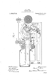
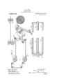
In the drawings,-Figure 1 isf vertical section through such a press, showing my improved lo'op forming mechanism, and showing the impression cylinders theiend of their printing stroke; Fig. 2, i" a diagrammatic illustration of the essential Ipression Cylinders at the end of their return stroke and ready to begin their printing movemenfl, Fig 3 is an enlarged detaill being a view ofthe rocking frame by which the looping of the web is effected, and biioken awa Rgferring to the drawings :-4 indicates the frame of the press having type-beds 5- 6.
7 indicates a roll-spindle carrying the web 8.
9 indicates a guide upon which travels web-governor 10, which is of the well known type and description, described in previous patents to me, and forming no part of my present invention except as an element in the combination, 'need not be further de scribed. I
11 indicates the main driving shaft of the press carrying at one end a fiy-wheel 12.
13 indicates a cam-which is secured upon 14-15-16-17'18-'19 indicate rollers which are journaled in any suitable manner upon the frame 4, and around which the Application was 5, 1910. .Serial No. 559,467.
S, A CORPORATION ,OF ILLINOIS.
(i-PRESS.
Letters Patent. Patented Feb. 11, 1913.
It will be seen furtherfrom Figs 1 and 2 that the rollers 14 and 15 constitute supports for a downwardly extending loop of the web in which the governor 10 rests by gravity, thereby preventing the direct and positive feed of the looper 34 jerking upon the web roll 7 and thus breaking the web. It'will be understood that the mechanism and' arrangement just described, together with the cooperating parts constitutes an embodiment of means for forming a reserve any appropriate mechanism, not shown, which travel at a constant speed and operate as forwarding rollers, to pull the web through the press in the well known manner. 2223 indicate other driven forwarding rollers mounted upon suitable brackets on the framework, and operating to forward the web into any other mechanism for subsequent treatment. I
. 24 indicates a carriage which travels on suitable guides, as 25 (see dotted lines in Fig. 1), and reciprocates backward and for-- ward over type-beds 56. The carriage is reciprocated by any suitable mechanism, as by connecting rod 26 pivotally connected at one endwith said carriage and at the other end with fiy-wheel 12. This reciprocating mechanism, however, may be of any well known kind and description, and forming no part of my present invention,and being wel'l understood, it is believed that it is unnecessary to describe it further here. M 27-28 indicate impression cylinders which are journaled in carriage 24 and which coact with the type-beds 5-6, respectively, to print'the paper. It will, of course, be understood that in the completed lpliedwith mechanism adapted to raise them from the type-bed, at the end oftheir impression stroke, for the returnstroke, and to lower stroke, for the impression stroke. Such mechanisms are well understood in-the art, and, as far as my invention is concerned, may be of any well known kind and mode of operation, forming no art of my present invent-ion, and, there ore,'I believe it is not necessary to fully illustrate or describe the same, and have accordingly only indicated the same in the drawings in order to avoid unnecessary complexity and confusion therein. a
loop between the looper 34 and .the web roll.
2021 indicate driven rollers driven by press the impression cylinders will be supf them at the end of the return I 29 indicates a rocking frame which is shown in detail, broken away, in Fig. 3, and which is composed of a rock-shaft 30, journaled in the frame of the machine, side bars 31, secured midway of their length upon the rock-shaft 30, and rollers 33-34 journaled at each end of the side bars 31. y
35 indicates an arm rigid with the rockshaft 30, and carrying at its outer end a roller 36, which registers with the surface of the cam 13, and is held against the same by an extension coiled spring 37 which connects one of the side-bars 31 with a suitable part of the frame 4. I have shown the cam 13 as an open one with the roller held against it by a spring, but it'is, of course,
obvious that a closed cam may be used in stead if desired.
By reference to the drawing it will be noted that the reserve loop of variable length is maintained in the web 8 between the web roll on support 7 and the loop formed over looper roll 34, and which takes a definite feed of web so as to space or .position the web properly. upon the forms.
As the main driving shaft rotates, carrying the parts in the direction shown by arrow in Fig. 1, the cam will operate through the rock-arm to rock the rock-shaft and thus rock the frame,,moving the rollers 33-34 backward and forward. The differ- 'ences between the high and the low part of the cam will be so proportioned, and the other parts so proportioned, that the rollers 3334 will travel just the right amount to take up and give off the proper length of web. For instance, in the construction shown, if the length of the printed page, in the direction of the travel of the cylinders, is 22 inches, the rollers will travel back and forth through a space ofli}- inches so as to make a loop, taking up or giving out, in each case, 11 inches of the web. The web, from the web-roll 7, passes over roller 14, through the web-governor 10, over rollers. 15l7, over roller 34 on the lower end 'of the rocking frame, over guide-roller 37 lows: In Fig. 1, as has been said, the im-' pression cylinders are at 'the end of the impression stroke, the roller 3fi is at the lowest point of the cam, and the frame has-been rocked so that the upper roller 33 is at. its
extreme left position in Fig. 1, the. roller lifted from the type-bed in any well known way, begins, -and the web is free to move between the impression cylinders and the type-bed. The cam, operating upon roller 36, begins to rock the frame 29 back again, that is to say, i moves the upper roller 33 to the right and the lower roller 34 to the left. The constantly traveling rollers 20-21 and-22-23 carry the web forward, and the roller 34, traveling to the left during this return'movement of the cylinder, gives up to the traveling web the loop'which has been formed by its movement to the right. At the. same time the roller 33, moving tothe right, forms a loop in the web, and ,of the same length as the loop that has been formed by roller'34 and which is now being given up, as above set forth, until, at the completion of the return stroke of the cylinders', the parts have reached the position shown in Fig. 2, in which the entire loop formed by therollcr 34 is given up and a new loop of the same lengthpmade in the web by roller 33, and by the combined action of the roller 33 and the feeding rollers 2021 the web has been moved forward one page length through the press and is ready for the next impression. The impression cylinders then descend upon the typebed and-begin their impression movement. As soonas they close upon the type-bed the web is, of course, prevented from moving forward at any point between the lower impression cylinder and roller 33. The roller 33, however, thereupon moving to the left, gives up the material of the loop, just taken up by it, to the constantly driven rollers 2021 and the web, continuously fed into direct rigid connections between the loopers and their cam shaft, and also the reserve loop between the web roll and 'the first looper cooperate to avoid the frequent breakages of the web which have heretofore constituted one of the greatest drawbacks in this kind of presses. The long and vexatious delays, the tedious and unpleasant labor, and the great loss of time in getting out a newspaper edition, resulting from such breakages, as well as the other attendant drawbacks will be clearly understood without'detailed explanation thereof. Of course the above operation is repeated with eadi reciprocation forward and backward of the impression cylinders. By the. construction so v bination a pluralityof stationary reciprocate the carriage,
provide a much simpler construction than has heretofore been used, for the alternate forming and giving up of the loops in the web, and do away with considerable complicationofmechanism, and also provide a looping mechanism which may be driven directly from the main driving shaft of the press.
That which I claim as my invention and desire to secure by Letters Patent is;
1. A web printing press including in combination two stationary beds, one above another, a- ,reciprocating carriage, a driving shaft, connections between said driving shaftand said carrlage to reciprocate the carriage, two impression cylinders mounted on said carriage and adapted to roll along said beds to perfect a web, vibrating web looping means, an actuating device fixed to said shaft, and rigid connections from said web looping means to said actuating device whereby said looping means is vibrated.
2. A web printing press including in comtype beds a carriage reciprocating along said type beds, impression cylinders mountedon said carriage and adapted to roll along said type beds to perfect a web, a driving shaft, connections between said shaft and carriage to a web looping device comprising bars supporting a roller over which the web passes and an arm rigid with said bars, and a cam fixed on said driving shaft directly actuating said rigid arm to vibrate said looping device.
3. A web printing press including in combination two fixed beds one above another,
a carriage reciprocating along said beds, a driving shaft, connections from said' driving shaft to said carriage to reciprocate the carriage, two impression cylinders mounted on said carriage and adapted to roll along said beds to perfect ajweb, web looping means comprising a vertically arranged rocking frame journaled intermediate its ends, a single roller at each end of said rocking frame over which the web passes, and comprising an arm rigid with said frame, and an actuating device for said arm fixed on said driving shaft.
4:. A web printing press including in combination two fixed-beds one above another, a carriage reciprocating along said beds, a driving shaft, connections from said driving shaftto said carriage to reciprocate the carriage, two impression cylinders mounted on said carriage and adapted to roll along said beds toperfec a web, web looping means comprising a vertically arranged rocking frame ournaled intermediate its ends, a sin- Copies of this patent may be obtained in gle roller at each end of said rocking frame over which the web passes, and comprising an arm rigid with said frame, and a cam fixed on said driving shaft and directly actuating said rigid arm.
5. A web printing press including in combination two stationary beds, two impression cylinders adapted to roll along said beds to perfect a web, means for actuating said cylinders, means for forming a loop in said,
web of definite length before .it passes to the first bed and after it leaves the second bed, means located'between said loop forming means and the source of web supply comprising supports for a downwardly extending loop and a freely moving member resting by gravity in said downwardly extending loop, to maintain a variable reserve loop between the web supply and said definite loop forming means.
6. A web printing press including in combination asource of web supplyytwo stationary beds,two impressioni cylinders adapted to roll along said beds to perfect a web, means for actuating said cylinders, means for intermittently forming in the web a loop of definite length after it passes from the second bed, means for intermittently forming in the web a loop of definite length before it passes to the first bed. and means for forming a reserve loop between the source/of web supply and said last mentioned intermittent loop forming means.
7. A web printing press including in combinat-ion two stationary beds, two impres ion cylinders adapted to roll along said beds to perfect a web, means for actuating said cylinders, means for forming a loop in said web of definite length before it passes to the first bed and after it leaves the second bed, means located between said loop forming means and the sourcexof web supply, comprising supports for a downwardly extending loop and a freely moving member resting by gravity in said downwardly extending loop. and guides to control the travel of said freely moving member.
8. A web printing press including in combination a stationary form bed, an impression cylinder dapted to IOllEllOllg said bed,
a web suppl means locate between said form bedand web supply for intermittently forming a loop in said web, means for forming a reserve loop between said intermittent loop forming means and said web supply, and means for forwarding the web from said form bed.
PAUL F. COX.
Witnesses:
CHARLES E. PICKARD, W. H. De Bnsn.
five cents each, by addressing the Cong. wsioner of Eatents, Washington, 1b. C.
Priority Applications (1)
| Application Number | Priority Date | Filing Date | Title |
|---|---|---|---|
| US55946710A US1052712A (en) | 1910-05-05 | 1910-05-05 | Printing-press. |
Applications Claiming Priority (1)
| Application Number | Priority Date | Filing Date | Title |
|---|---|---|---|
| US55946710A US1052712A (en) | 1910-05-05 | 1910-05-05 | Printing-press. |
Publications (1)
| Publication Number | Publication Date |
|---|---|
| US1052712A true US1052712A (en) | 1913-02-11 |
Family
ID=3120973
Family Applications (1)
| Application Number | Title | Priority Date | Filing Date |
|---|---|---|---|
| US55946710A Expired - Lifetime US1052712A (en) | 1910-05-05 | 1910-05-05 | Printing-press. |
Country Status (1)
| Country | Link |
|---|---|
| US (1) | US1052712A (en) |
-
1910
- 1910-05-05 US US55946710A patent/US1052712A/en not_active Expired - Lifetime
Similar Documents
| Publication | Publication Date | Title |
|---|---|---|
| US1592123A (en) | Ribbon-printing attachment for presses | |
| US359442A (en) | Oscillating-cylinder printing-machine | |
| US678044A (en) | Sheet-delivery apparatus. | |
| US189829A (en) | Improvement in printing-presses | |
| US666328A (en) | Web-feeding and compensating mechanism for printing-machines. | |
| US809241A (en) | Flat-bed web-printing press. | |
| US376053A (en) | Web-printing machine | |
| US818699A (en) | Combined printing and cutting machine. | |
| US1747662A (en) | Traveling-cylinder printing press | |
| US553480A (en) | Printing press | |
| US581436A (en) | Printing-machine | |
| US1089342A (en) | Piling-table for printing-presses. | |
| US942980A (en) | Printing-machine. | |
| US590617A (en) | Registering and tripping mechanism for printing-presses | |
| US805620A (en) | Web-manipulating mechanism for printing-presses. | |
| US208796A (en) | Improvement in delivery apparatus for printing-machines | |
| US910363A (en) | Printing-press. | |
| US424097A (en) | Cylinder printing-machine | |
| US689518A (en) | Printing-machine. | |
| US663864A (en) | Collotype or similar printing machine. | |
| US1449215A (en) | Web-printing press | |
| US433214A (en) | Frisket-placing apparatus for printing-machines | |
| US680128A (en) | Printing-press. | |
| US569310A (en) | Printing-press | |
| US492054A (en) | The nor |