US10523043B2 - Air powered battery charger - Google Patents
Air powered battery charger Download PDFInfo
- Publication number
- US10523043B2 US10523043B2 US15/976,280 US201815976280A US10523043B2 US 10523043 B2 US10523043 B2 US 10523043B2 US 201815976280 A US201815976280 A US 201815976280A US 10523043 B2 US10523043 B2 US 10523043B2
- Authority
- US
- United States
- Prior art keywords
- air
- platform
- piston
- ramp
- generator
- Prior art date
- Legal status (The legal status is an assumption and is not a legal conclusion. Google has not performed a legal analysis and makes no representation as to the accuracy of the status listed.)
- Expired - Fee Related, expires
Links
- 230000006835 compression Effects 0.000 claims description 3
- 238000007906 compression Methods 0.000 claims description 3
- 230000008901 benefit Effects 0.000 description 7
- 238000000034 method Methods 0.000 description 5
- 239000000463 material Substances 0.000 description 3
- 230000008569 process Effects 0.000 description 3
- 230000000994 depressogenic effect Effects 0.000 description 2
- 230000005611 electricity Effects 0.000 description 2
- 229910052751 metal Inorganic materials 0.000 description 2
- 239000002184 metal Substances 0.000 description 2
- 230000004048 modification Effects 0.000 description 2
- 238000012986 modification Methods 0.000 description 2
- 239000004033 plastic Substances 0.000 description 2
- 239000002023 wood Substances 0.000 description 2
- 229910000831 Steel Inorganic materials 0.000 description 1
- 239000000654 additive Substances 0.000 description 1
- 210000004712 air sac Anatomy 0.000 description 1
- 229910052782 aluminium Inorganic materials 0.000 description 1
- XAGFODPZIPBFFR-UHFFFAOYSA-N aluminium Chemical compound [Al] XAGFODPZIPBFFR-UHFFFAOYSA-N 0.000 description 1
- 230000004888 barrier function Effects 0.000 description 1
- 230000008859 change Effects 0.000 description 1
- 230000007812 deficiency Effects 0.000 description 1
- 238000009792 diffusion process Methods 0.000 description 1
- 229920001971 elastomer Polymers 0.000 description 1
- 239000000806 elastomer Substances 0.000 description 1
- 238000003487 electrochemical reaction Methods 0.000 description 1
- 239000002803 fossil fuel Substances 0.000 description 1
- ZZUFCTLCJUWOSV-UHFFFAOYSA-N furosemide Chemical compound C1=C(Cl)C(S(=O)(=O)N)=CC(C(O)=O)=C1NCC1=CC=CO1 ZZUFCTLCJUWOSV-UHFFFAOYSA-N 0.000 description 1
- 230000005484 gravity Effects 0.000 description 1
- 238000005286 illumination Methods 0.000 description 1
- 239000010705 motor oil Substances 0.000 description 1
- 230000008707 rearrangement Effects 0.000 description 1
- 230000002441 reversible effect Effects 0.000 description 1
- 239000007787 solid Substances 0.000 description 1
- 239000010959 steel Substances 0.000 description 1
Images


Classifications
-
- H—ELECTRICITY
- H02—GENERATION; CONVERSION OR DISTRIBUTION OF ELECTRIC POWER
- H02J—CIRCUIT ARRANGEMENTS OR SYSTEMS FOR SUPPLYING OR DISTRIBUTING ELECTRIC POWER; SYSTEMS FOR STORING ELECTRIC ENERGY
- H02J7/00—Circuit arrangements for charging or depolarising batteries or for supplying loads from batteries
- H02J7/32—Circuit arrangements for charging or depolarising batteries or for supplying loads from batteries for charging batteries from a charging set comprising a non-electric prime mover rotating at constant speed
-
- B—PERFORMING OPERATIONS; TRANSPORTING
- B60—VEHICLES IN GENERAL
- B60L—PROPULSION OF ELECTRICALLY-PROPELLED VEHICLES; SUPPLYING ELECTRIC POWER FOR AUXILIARY EQUIPMENT OF ELECTRICALLY-PROPELLED VEHICLES; ELECTRODYNAMIC BRAKE SYSTEMS FOR VEHICLES IN GENERAL; MAGNETIC SUSPENSION OR LEVITATION FOR VEHICLES; MONITORING OPERATING VARIABLES OF ELECTRICALLY-PROPELLED VEHICLES; ELECTRIC SAFETY DEVICES FOR ELECTRICALLY-PROPELLED VEHICLES
- B60L53/00—Methods of charging batteries, specially adapted for electric vehicles; Charging stations or on-board charging equipment therefor; Exchange of energy storage elements in electric vehicles
- B60L53/50—Charging stations characterised by energy-storage or power-generation means
-
- B—PERFORMING OPERATIONS; TRANSPORTING
- B60—VEHICLES IN GENERAL
- B60L—PROPULSION OF ELECTRICALLY-PROPELLED VEHICLES; SUPPLYING ELECTRIC POWER FOR AUXILIARY EQUIPMENT OF ELECTRICALLY-PROPELLED VEHICLES; ELECTRODYNAMIC BRAKE SYSTEMS FOR VEHICLES IN GENERAL; MAGNETIC SUSPENSION OR LEVITATION FOR VEHICLES; MONITORING OPERATING VARIABLES OF ELECTRICALLY-PROPELLED VEHICLES; ELECTRIC SAFETY DEVICES FOR ELECTRICALLY-PROPELLED VEHICLES
- B60L8/00—Electric propulsion with power supply from forces of nature, e.g. sun or wind
- B60L8/006—Converting flow of air into electric energy, e.g. by using wind turbines
-
- H—ELECTRICITY
- H02—GENERATION; CONVERSION OR DISTRIBUTION OF ELECTRIC POWER
- H02J—CIRCUIT ARRANGEMENTS OR SYSTEMS FOR SUPPLYING OR DISTRIBUTING ELECTRIC POWER; SYSTEMS FOR STORING ELECTRIC ENERGY
- H02J7/00—Circuit arrangements for charging or depolarising batteries or for supplying loads from batteries
-
- H—ELECTRICITY
- H02—GENERATION; CONVERSION OR DISTRIBUTION OF ELECTRIC POWER
- H02J—CIRCUIT ARRANGEMENTS OR SYSTEMS FOR SUPPLYING OR DISTRIBUTING ELECTRIC POWER; SYSTEMS FOR STORING ELECTRIC ENERGY
- H02J9/00—Circuit arrangements for emergency or stand-by power supply, e.g. for emergency lighting
- H02J9/04—Circuit arrangements for emergency or stand-by power supply, e.g. for emergency lighting in which the distribution system is disconnected from the normal source and connected to a standby source
- H02J9/06—Circuit arrangements for emergency or stand-by power supply, e.g. for emergency lighting in which the distribution system is disconnected from the normal source and connected to a standby source with automatic change-over, e.g. UPS systems
- H02J9/062—Circuit arrangements for emergency or stand-by power supply, e.g. for emergency lighting in which the distribution system is disconnected from the normal source and connected to a standby source with automatic change-over, e.g. UPS systems for AC powered loads
-
- H—ELECTRICITY
- H02—GENERATION; CONVERSION OR DISTRIBUTION OF ELECTRIC POWER
- H02J—CIRCUIT ARRANGEMENTS OR SYSTEMS FOR SUPPLYING OR DISTRIBUTING ELECTRIC POWER; SYSTEMS FOR STORING ELECTRIC ENERGY
- H02J9/00—Circuit arrangements for emergency or stand-by power supply, e.g. for emergency lighting
- H02J9/04—Circuit arrangements for emergency or stand-by power supply, e.g. for emergency lighting in which the distribution system is disconnected from the normal source and connected to a standby source
- H02J9/06—Circuit arrangements for emergency or stand-by power supply, e.g. for emergency lighting in which the distribution system is disconnected from the normal source and connected to a standby source with automatic change-over, e.g. UPS systems
- H02J9/08—Circuit arrangements for emergency or stand-by power supply, e.g. for emergency lighting in which the distribution system is disconnected from the normal source and connected to a standby source with automatic change-over, e.g. UPS systems requiring starting of a prime-mover
-
- H—ELECTRICITY
- H02—GENERATION; CONVERSION OR DISTRIBUTION OF ELECTRIC POWER
- H02K—DYNAMO-ELECTRIC MACHINES
- H02K7/00—Arrangements for handling mechanical energy structurally associated with dynamo-electric machines, e.g. structural association with mechanical driving motors or auxiliary dynamo-electric machines
- H02K7/18—Structural association of electric generators with mechanical driving motors, e.g. with turbines
- H02K7/1807—Rotary generators
- H02K7/1853—Rotary generators driven by intermittent forces
-
- Y—GENERAL TAGGING OF NEW TECHNOLOGICAL DEVELOPMENTS; GENERAL TAGGING OF CROSS-SECTIONAL TECHNOLOGIES SPANNING OVER SEVERAL SECTIONS OF THE IPC; TECHNICAL SUBJECTS COVERED BY FORMER USPC CROSS-REFERENCE ART COLLECTIONS [XRACs] AND DIGESTS
- Y02—TECHNOLOGIES OR APPLICATIONS FOR MITIGATION OR ADAPTATION AGAINST CLIMATE CHANGE
- Y02T—CLIMATE CHANGE MITIGATION TECHNOLOGIES RELATED TO TRANSPORTATION
- Y02T10/00—Road transport of goods or passengers
- Y02T10/60—Other road transportation technologies with climate change mitigation effect
- Y02T10/64—Electric machine technologies in electromobility
-
- Y—GENERAL TAGGING OF NEW TECHNOLOGICAL DEVELOPMENTS; GENERAL TAGGING OF CROSS-SECTIONAL TECHNOLOGIES SPANNING OVER SEVERAL SECTIONS OF THE IPC; TECHNICAL SUBJECTS COVERED BY FORMER USPC CROSS-REFERENCE ART COLLECTIONS [XRACs] AND DIGESTS
- Y02—TECHNOLOGIES OR APPLICATIONS FOR MITIGATION OR ADAPTATION AGAINST CLIMATE CHANGE
- Y02T—CLIMATE CHANGE MITIGATION TECHNOLOGIES RELATED TO TRANSPORTATION
- Y02T10/00—Road transport of goods or passengers
- Y02T10/60—Other road transportation technologies with climate change mitigation effect
- Y02T10/70—Energy storage systems for electromobility, e.g. batteries
-
- Y—GENERAL TAGGING OF NEW TECHNOLOGICAL DEVELOPMENTS; GENERAL TAGGING OF CROSS-SECTIONAL TECHNOLOGIES SPANNING OVER SEVERAL SECTIONS OF THE IPC; TECHNICAL SUBJECTS COVERED BY FORMER USPC CROSS-REFERENCE ART COLLECTIONS [XRACs] AND DIGESTS
- Y02—TECHNOLOGIES OR APPLICATIONS FOR MITIGATION OR ADAPTATION AGAINST CLIMATE CHANGE
- Y02T—CLIMATE CHANGE MITIGATION TECHNOLOGIES RELATED TO TRANSPORTATION
- Y02T10/00—Road transport of goods or passengers
- Y02T10/60—Other road transportation technologies with climate change mitigation effect
- Y02T10/7072—Electromobility specific charging systems or methods for batteries, ultracapacitors, supercapacitors or double-layer capacitors
-
- Y—GENERAL TAGGING OF NEW TECHNOLOGICAL DEVELOPMENTS; GENERAL TAGGING OF CROSS-SECTIONAL TECHNOLOGIES SPANNING OVER SEVERAL SECTIONS OF THE IPC; TECHNICAL SUBJECTS COVERED BY FORMER USPC CROSS-REFERENCE ART COLLECTIONS [XRACs] AND DIGESTS
- Y02—TECHNOLOGIES OR APPLICATIONS FOR MITIGATION OR ADAPTATION AGAINST CLIMATE CHANGE
- Y02T—CLIMATE CHANGE MITIGATION TECHNOLOGIES RELATED TO TRANSPORTATION
- Y02T90/00—Enabling technologies or technologies with a potential or indirect contribution to GHG emissions mitigation
- Y02T90/10—Technologies relating to charging of electric vehicles
- Y02T90/12—Electric charging stations
Definitions
- the present invention relates generally to the field of battery chargers. More particularly, the present invention concerns an air powered battery charger.
- batteries are powered by batteries. While an efficient and portable source of power, batteries drain when used and can reach a state of depletion. When depleted, batteries cannot supply electrical power. However, through reversible electrochemical reactions, some batteries can be recharged by re-separating certain elements. The process can be slow and facilitated by diffusion, or it can be accelerated by an alternate source of energy. Consumers are familiar with the latter, when they plug in a charging station to a wall outlet and let AC current recharge their batteries. However, such processes consume electricity, which can itself be a problem. What is needed is a renewable, easily provided source of electricity that charges the batteries.
- the present invention relates to an air powered battery charger that overcomes the deficiencies of the prior art.
- the general purpose of the present invention which shall be described subsequently in greater detail, is to use a vehicle's weight to compress air and thereby to charge a battery.
- the present invention comprises an air powered battery charger.
- the present invention provides for a ramp with a platform attached to a piston that, when depressed by a vehicle or large object with enough mass to displace air from the piston to pressurize an air holding tank.
- the air holding tank can either be used similar to an air compressor tank, or the air holding tank can be used to run an air motor connected to an alternator generator to recharge batteries.
- the present invention may be used to recharge batteries for household use, or for other uses, faster and less expensively than solar or wind generation.
- the amount of power generated by the present invention may depend on the mass applied and the frequency at which the pump is depressed as well as the holding tank and components involved in the generating functionality. Additionally, in some embodiments, the size of the pump configuration will depend on the vehicle or mass expected to be applied to the task.
- a user To operate the present invention, a user must first move a heavy object, such as but not limited to a vehicle, onto the platform. Then, the platform with piston underneath compresses the closing intake valve (in some embodiments closing the intake valve). Next, the present invention's exhaust valve opens, sending air into the tank, trapping it. Once the piston reaches the bottom, which in some embodiments indicates the piston is fully compressed, the user may remove the vehicle or other object. Then, the present invention's intake value opens by springs, or in conjunction with such springs, that force the platform up. The upward thrust may draw air into an air motor coupled to a generator, which may send power to a battery pack.
- a heavy object such as but not limited to a vehicle
- the user may reapply the object onto the platform, which causes the present invention to close the intake and open the exhaust to the tank, which in turn may remain open until pressure equalizes, or the tank is emptied from a valve to an air motor supply or general use.
- the present invention may also provide for a mobile or other form of software application that enables a user, at least, to check the system pressure and its status.
- an application may be provided that enables a user to control or direct one or more functions of the previous invention, including but not limited to the amount, pace, or manner in batteries are charged.
- the present invention may be portable, and may provide for one or more forklift-accommodating depressions, or other depressions, that may enable a machine to pick up and transport the present invention.
- the present invention may also provide for one or more emergency shut off valves or switches.
- the weight of a vehicle on a bridge or ramp, or other heavy object in a similar spot may depress air springs and one or more pistons, which drives air into an air tank (which may store the air), which drives an air motor, which powers an alternator generator, which supplies power to batteries and recharges them, which are then used, via an inverter, to supply usable electrical power.
- an air tank which may store the air
- an air motor which powers an alternator generator, which supplies power to batteries and recharges them, which are then used, via an inverter, to supply usable electrical power.
- This product may provide the following benefits for consumers everywhere: it may provide a renewable source of electrical power that quickly and easily recharges batteries, it may be used to power air motors, air generators, and other similar devices, and it may save consumers money by reducing energy costs.
- FIG. 1 shows a front perspective view of an air powered battery charger in accordance with an embodiment of the invention.
- FIG. 2 shows a top perspective view of an air powered battery charger in accordance with an embodiment of the invention.
- FIG. 3 shows a rear view of an air powered battery charger in accordance with an embodiment of the invention.
- FIG. 4 shows a top front perspective view of an air powered battery charger in accordance with an embodiment of the invention.
- the present invention overcomes the limitations of the prior art by providing a new and more effective air powered battery charger.
- FIG. 1 a front perspective view of an air powered battery charger in accordance with an embodiment of the invention is shown.
- a viewer may perceive air powered battery charger 100 , ramp 101 , platform 102 , springs 103 , piston 104 .
- ramp 101 may be comprised of any material known in the art, such as but not limited to metal, wood, or plastic.
- one or more ramps 101 may provide for one or more hinges that enable ramp 101 to fold or change its shape.
- ramp 101 may be replaced by an elevator.
- the orientations of one or more ramps 101 may be changed such that the vehicle comes down one or more ramps 101 to reach platform 102 .
- One or more ramps 101 may also provide for one or more perforations so as to, for example, allow motor oil to pass through ramp 101 .
- one or more ramps 101 may provide for illumination, guardrails, or other similar features.
- one or more ramps 101 may provide for one or more wheels at the end of ramp 101 .
- Platform 102 may be of any material with sufficient strength to withstand the weight of a heavy object, such as but not limited to metal, wood, or plastic. Moreover, in some embodiments, platform 102 may provide for one or more raised traction elements, or surface ornamentation such as elastomer portions that enable a vehicle's wheels to stay put on top of platform 102 . In some embodiments, the present invention may provide for two or more platforms 102 , which may be connected or operating independently. Also, in some embodiments, one or more spring guides go inside one or more railings. There may also be an arched ramp 101 attached to platform 102 , which may be pinned close to or above the wheels in relationship ramp 101 or piston 104 . Platform 102 may also provide one or more hinges at the points of connection between ramp(s) 101 and platform 102 .
- piston 104 may be sturdy and capable of repeated use in the manner contemplated. Additionally, while the embodiment shown in FIG. 1 and elsewhere herein generally discloses a one to one relationship between platform 102 and piston 104 , in some embodiments more than one platform 102 may be connected to one piston 104 , one platform 102 may be connected to more than one piston 104 , more than one piston 102 may be connected to more than one platform 104 , and so forth.
- the present invention may also provide for a light (not shown) that illuminates red when piston 104 reaches the bottom and green when piston 104 is decompressing.
- a two-inch ball valve intake may provide for a K+N air filter or any reusable filter.
- the present invention may provide for forklift access holes that may enable portable use.
- the present invention may also provide for a one-inch exit pipe to an air tank, as well as an emergency shut off switch.
- ramp(s) 101 , piston(s) and other elements of the present invention may be aluminum for lightweight properties.
- the present invention may provide for piston(s) 104 and piston rings located above a compression chamber.
- the present invention may also provide for one or more ramp pins, which in some embodiments may be located in alignment with a vehicle's wheels.
- the present invention may be three feet tall, ten feet wide and sixteen feet wide, or any size capable compatible with the present invention's functionalities.
- FIG. 2 a top perspective view of an air powered battery charger in accordance with an embodiment of the invention is shown.
- a viewer may perceive air powered battery charger 100 , ramp 101 , platform 102 , springs 103 , piston 104 .
- FIG. 2 serves to show generally a different angle of the relationship between platform 102 and ramps 101 .
- a user may also generally see the relationship between piston 104 and platform 102 , wherein platform 102 extends beyond piston 104 .
- platform 102 may be flush with piston 104 , or in some embodiments piston 104 may extend further laterally than platform 102 .
- FIG. 2 also serves to illustrate the relationship between the edges of platform 102 and those of ramps 101 .
- the line between platform 102 and ramp(s) 101 is not straight, but rather alternatingly notched.
- the edges between platform 102 and ramp(s) 101 may be straight, arcuate, or any other shape.
- the railings of platform 102 are shown in FIG. 2 as right angles, but the railings of platform 102 may be of any shape preferable, such as arcuate half circles, strap-handles, solid barriers, triangles, and so forth.
- FIG. 3 a rear view of an air powered battery charger in accordance with an embodiment of the invention is shown.
- a viewer may perceive battery charger 100 , air tank 301 , air motor 302 , generator 303 , and battery pack 304 , as well as ramp 101 , platform 102 , springs 103 , piston 104 .
- the present invention may provide for a one-inch line that passes from piston 104 to air tank 301 , which may be a fifty gallon or more air tank 301 . Then, via a quarter-inch pipe, the air may pass one of two ways: through a regulator quarter-inch to a garage or barn for use, for example, with inflating tires (not pictured). It may also pass through a regulator quarter-inch oiler, then to an air motor 302 at approximately fifty pounds per square inch (PSI) which in some embodiments may be attached to an alternator/generator 303 . Generator 303 may be in turn attached to a battery bank or battery pack 304 . In some embodiments, battery pack 304 may in turn be connected to a house hydro with (wife) system monitor that evaluates, at least, battery charge level and tank pressure.
- PSI pounds per square inch
- generator 303 may be in turn attached to a battery bank or battery pack 304 .
- battery pack 304 may in turn be connected to a house hydro with (wife) system monitor that
- the present invention may also provide that platform 102 , and in some embodiments an air filter in platform 102 , may have an approximately two-inch intake and an approximately one-inch exit.
- the air from platform 102 may flow through a ball valve into air tank 301 , which in some embodiments, may be a quarter-inch all-purpose air tank 301 .
- the tube carrying the air may be quarter-inch all purpose.
- the ball valve may provide for an intake steel ball that is larger and reversed from the exhaust.
- the ball valve may also provide for a quarter-inch exit with a regulator.
- the air may then pass through an electric ball valve to air motor 302 mated to generator 303 or an alternator.
- Generator 303 or an alternator may be connected to an inverter panel which can also check the battery levels of one or more batteries or at least one battery pack 304 .
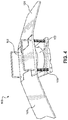
- FIG. 4 a top front perspective view of an air powered battery charger in accordance with an embodiment of the invention is shown.
- a viewer may perceive air powered battery charger 100 , ramp 101 , platform 102 , springs 103 , piston 104 .
- FIG. 4 serves to generally show a zoomed-out perspective of air powered battery charger 100 , wherein the length of ramp 101 may be better perceived, as well as the optionally-provided wheels that may be provided at the end of one or more ramps 101 .
- one or more ramps 101 may serve one or more platforms 102 , and that any size, shape, thickness, or properties of any element are herein contemplated, including but not limited to ramp 101 , platform 102 , springs 103 , piston 104 .
- ramp 101 may be longer or shorter than shown in FIG. 4 .
Abstract
Description
Claims (8)
Priority Applications (1)
| Application Number | Priority Date | Filing Date | Title |
|---|---|---|---|
| US15/976,280 US10523043B2 (en) | 2017-05-10 | 2018-05-10 | Air powered battery charger |
Applications Claiming Priority (2)
| Application Number | Priority Date | Filing Date | Title |
|---|---|---|---|
| US201762504007P | 2017-05-10 | 2017-05-10 | |
| US15/976,280 US10523043B2 (en) | 2017-05-10 | 2018-05-10 | Air powered battery charger |
Publications (2)
| Publication Number | Publication Date |
|---|---|
| US20180331565A1 US20180331565A1 (en) | 2018-11-15 |
| US10523043B2 true US10523043B2 (en) | 2019-12-31 |
Family
ID=64097925
Family Applications (1)
| Application Number | Title | Priority Date | Filing Date |
|---|---|---|---|
| US15/976,280 Expired - Fee Related US10523043B2 (en) | 2017-05-10 | 2018-05-10 | Air powered battery charger |
Country Status (1)
| Country | Link |
|---|---|
| US (1) | US10523043B2 (en) |
Citations (7)
| Publication number | Priority date | Publication date | Assignee | Title |
|---|---|---|---|---|
| US5180283A (en) * | 1991-07-05 | 1993-01-19 | Vickery Iii Earle R | Manual two-stage air pump |
| US6293771B1 (en) * | 1998-10-27 | 2001-09-25 | Thomson Licensing S.A. | Manually-powered apparatus for powering a portable electronic device |
| US20040148934A1 (en) * | 2003-02-05 | 2004-08-05 | Pinkerton Joseph F. | Systems and methods for providing backup energy to a load |
| US8228031B2 (en) * | 2008-08-22 | 2012-07-24 | Motorola Mobility, Inc. | Apparatus for charging a portable electronic device using a rotatable turbine |
| US20120313575A1 (en) * | 2008-03-11 | 2012-12-13 | Physics Lab Of Lake Havasu, Llc | Regenerative suspension with accumulator systems and methods |
| US20140175798A1 (en) * | 2012-12-20 | 2014-06-26 | Howard G. Hoose, JR. | Power generation system and method of use thereof |
| US20150013083A1 (en) * | 2011-12-14 | 2015-01-15 | Systems, Inc. | Centralized Air Supply Loading Dock Leveling System |
-
2018
- 2018-05-10 US US15/976,280 patent/US10523043B2/en not_active Expired - Fee Related
Patent Citations (7)
| Publication number | Priority date | Publication date | Assignee | Title |
|---|---|---|---|---|
| US5180283A (en) * | 1991-07-05 | 1993-01-19 | Vickery Iii Earle R | Manual two-stage air pump |
| US6293771B1 (en) * | 1998-10-27 | 2001-09-25 | Thomson Licensing S.A. | Manually-powered apparatus for powering a portable electronic device |
| US20040148934A1 (en) * | 2003-02-05 | 2004-08-05 | Pinkerton Joseph F. | Systems and methods for providing backup energy to a load |
| US20120313575A1 (en) * | 2008-03-11 | 2012-12-13 | Physics Lab Of Lake Havasu, Llc | Regenerative suspension with accumulator systems and methods |
| US8228031B2 (en) * | 2008-08-22 | 2012-07-24 | Motorola Mobility, Inc. | Apparatus for charging a portable electronic device using a rotatable turbine |
| US20150013083A1 (en) * | 2011-12-14 | 2015-01-15 | Systems, Inc. | Centralized Air Supply Loading Dock Leveling System |
| US20140175798A1 (en) * | 2012-12-20 | 2014-06-26 | Howard G. Hoose, JR. | Power generation system and method of use thereof |
Also Published As
| Publication number | Publication date |
|---|---|
| US20180331565A1 (en) | 2018-11-15 |
Similar Documents
| Publication | Publication Date | Title |
|---|---|---|
| CN101102050A (en) | Generator systems and methods | |
| US20110198141A1 (en) | Hydraulic electric hybrid drivetrain | |
| US20090277699A1 (en) | Power-generating plug-and-play vehicle | |
| US10523043B2 (en) | Air powered battery charger | |
| US20110278080A1 (en) | Drive system for a motor vehicle and method therefor | |
| US20190013755A1 (en) | Ambulatory recharging unit with bionic pneumatically-actuated generator | |
| CN108511996B (en) | A take-up for charging stake | |
| CN203201734U (en) | Pressure power generation device | |
| CN103147956B (en) | Wind-force air compression device | |
| US8890342B2 (en) | Air powered electrical generator | |
| US20140054900A1 (en) | System for generating electrical power | |
| CN204436698U (en) | Windmill high-energy compaction physics energy-storing and power-generating system | |
| CN111335450A (en) | Movable pump station and drainage emergency vehicle | |
| CN105386952A (en) | Piano type deceleration strip capable of generating electricity | |
| JP2000310102A (en) | Power generating method by pneumatics and device thereof | |
| WO2001092723A1 (en) | Electric compressor back sprayer | |
| CN206900178U (en) | A kind of New-energy electric vehicle charging pile for being mountable to solar street light lamp stand | |
| CN205823589U (en) | Electricity/dual-use manual inflator | |
| CN207835133U (en) | A kind of merchandising machine people | |
| CN104728051A (en) | Windmill high-powered compressed physical energy storage and power generation system | |
| CN214176944U (en) | Emergency charging station based on wind-solar hybrid power generation | |
| CN209297427U (en) | A kind of collapsible stopping for charging stake | |
| CN109018175A (en) | Green auxiliary power bicycle | |
| CN211816869U (en) | Movable pump station and drainage emergency vehicle | |
| CN211790951U (en) | Stable standby power supply system capable of being used for communication base station |
Legal Events
| Date | Code | Title | Description |
|---|---|---|---|
| FEPP | Fee payment procedure |
Free format text: ENTITY STATUS SET TO UNDISCOUNTED (ORIGINAL EVENT CODE: BIG.); ENTITY STATUS OF PATENT OWNER: MICROENTITY |
|
| FEPP | Fee payment procedure |
Free format text: ENTITY STATUS SET TO MICRO (ORIGINAL EVENT CODE: MICR); ENTITY STATUS OF PATENT OWNER: MICROENTITY |
|
| STPP | Information on status: patent application and granting procedure in general |
Free format text: DOCKETED NEW CASE - READY FOR EXAMINATION |
|
| STPP | Information on status: patent application and granting procedure in general |
Free format text: NOTICE OF ALLOWANCE MAILED -- APPLICATION RECEIVED IN OFFICE OF PUBLICATIONS |
|
| STPP | Information on status: patent application and granting procedure in general |
Free format text: PUBLICATIONS -- ISSUE FEE PAYMENT RECEIVED |
|
| STCF | Information on status: patent grant |
Free format text: PATENTED CASE |
|
| FEPP | Fee payment procedure |
Free format text: MAINTENANCE FEE REMINDER MAILED (ORIGINAL EVENT CODE: REM.); ENTITY STATUS OF PATENT OWNER: MICROENTITY |
|
| LAPS | Lapse for failure to pay maintenance fees |
Free format text: PATENT EXPIRED FOR FAILURE TO PAY MAINTENANCE FEES (ORIGINAL EVENT CODE: EXP.); ENTITY STATUS OF PATENT OWNER: MICROENTITY |
|
| STCH | Information on status: patent discontinuation |
Free format text: PATENT EXPIRED DUE TO NONPAYMENT OF MAINTENANCE FEES UNDER 37 CFR 1.362 |
|
| FP | Lapsed due to failure to pay maintenance fee |
Effective date: 20231231 |