US10516468B2 - Mechanisms for single frequency networks in high-speed mobile scenarios - Google Patents
Mechanisms for single frequency networks in high-speed mobile scenarios Download PDFInfo
- Publication number
- US10516468B2 US10516468B2 US15/772,473 US201615772473A US10516468B2 US 10516468 B2 US10516468 B2 US 10516468B2 US 201615772473 A US201615772473 A US 201615772473A US 10516468 B2 US10516468 B2 US 10516468B2
- Authority
- US
- United States
- Prior art keywords
- channel
- physical
- payload
- channel transmission
- parameters
- Prior art date
- Legal status (The legal status is an assumption and is not a legal conclusion. Google has not performed a legal analysis and makes no representation as to the accuracy of the status listed.)
- Active
Links
Images


Classifications
-
- H—ELECTRICITY
- H04—ELECTRIC COMMUNICATION TECHNIQUE
- H04B—TRANSMISSION
- H04B7/00—Radio transmission systems, i.e. using radiation field
- H04B7/02—Diversity systems; Multi-antenna system, i.e. transmission or reception using multiple antennas
- H04B7/04—Diversity systems; Multi-antenna system, i.e. transmission or reception using multiple antennas using two or more spaced independent antennas
- H04B7/08—Diversity systems; Multi-antenna system, i.e. transmission or reception using multiple antennas using two or more spaced independent antennas at the receiving station
- H04B7/0882—Diversity systems; Multi-antenna system, i.e. transmission or reception using multiple antennas using two or more spaced independent antennas at the receiving station using post-detection diversity
- H04B7/0888—Diversity systems; Multi-antenna system, i.e. transmission or reception using multiple antennas using two or more spaced independent antennas at the receiving station using post-detection diversity with selection
-
- H—ELECTRICITY
- H04—ELECTRIC COMMUNICATION TECHNIQUE
- H04B—TRANSMISSION
- H04B7/00—Radio transmission systems, i.e. using radiation field
- H04B7/02—Diversity systems; Multi-antenna system, i.e. transmission or reception using multiple antennas
- H04B7/022—Site diversity; Macro-diversity
-
- H—ELECTRICITY
- H04—ELECTRIC COMMUNICATION TECHNIQUE
- H04B—TRANSMISSION
- H04B7/00—Radio transmission systems, i.e. using radiation field
- H04B7/02—Diversity systems; Multi-antenna system, i.e. transmission or reception using multiple antennas
- H04B7/04—Diversity systems; Multi-antenna system, i.e. transmission or reception using multiple antennas using two or more spaced independent antennas
- H04B7/0413—MIMO systems
-
- H—ELECTRICITY
- H04—ELECTRIC COMMUNICATION TECHNIQUE
- H04L—TRANSMISSION OF DIGITAL INFORMATION, e.g. TELEGRAPHIC COMMUNICATION
- H04L25/00—Baseband systems
- H04L25/02—Details ; arrangements for supplying electrical power along data transmission lines
- H04L25/0202—Channel estimation
- H04L25/0204—Channel estimation of multiple channels
-
- H—ELECTRICITY
- H04—ELECTRIC COMMUNICATION TECHNIQUE
- H04L—TRANSMISSION OF DIGITAL INFORMATION, e.g. TELEGRAPHIC COMMUNICATION
- H04L25/00—Baseband systems
- H04L25/02—Details ; arrangements for supplying electrical power along data transmission lines
- H04L25/0202—Channel estimation
- H04L25/0224—Channel estimation using sounding signals
- H04L25/0228—Channel estimation using sounding signals with direct estimation from sounding signals
-
- H—ELECTRICITY
- H04—ELECTRIC COMMUNICATION TECHNIQUE
- H04L—TRANSMISSION OF DIGITAL INFORMATION, e.g. TELEGRAPHIC COMMUNICATION
- H04L5/00—Arrangements affording multiple use of the transmission path
- H04L5/003—Arrangements for allocating sub-channels of the transmission path
- H04L5/0044—Arrangements for allocating sub-channels of the transmission path allocation of payload
-
- H—ELECTRICITY
- H04—ELECTRIC COMMUNICATION TECHNIQUE
- H04L—TRANSMISSION OF DIGITAL INFORMATION, e.g. TELEGRAPHIC COMMUNICATION
- H04L5/00—Arrangements affording multiple use of the transmission path
- H04L5/003—Arrangements for allocating sub-channels of the transmission path
- H04L5/0048—Allocation of pilot signals, i.e. of signals known to the receiver
-
- H—ELECTRICITY
- H04—ELECTRIC COMMUNICATION TECHNIQUE
- H04B—TRANSMISSION
- H04B7/00—Radio transmission systems, i.e. using radiation field
- H04B7/02—Diversity systems; Multi-antenna system, i.e. transmission or reception using multiple antennas
- H04B7/04—Diversity systems; Multi-antenna system, i.e. transmission or reception using multiple antennas using two or more spaced independent antennas
- H04B7/06—Diversity systems; Multi-antenna system, i.e. transmission or reception using multiple antennas using two or more spaced independent antennas at the transmitting station
- H04B7/0613—Diversity systems; Multi-antenna system, i.e. transmission or reception using multiple antennas using two or more spaced independent antennas at the transmitting station using simultaneous transmission
- H04B7/0615—Diversity systems; Multi-antenna system, i.e. transmission or reception using multiple antennas using two or more spaced independent antennas at the transmitting station using simultaneous transmission of weighted versions of same signal
- H04B7/0617—Diversity systems; Multi-antenna system, i.e. transmission or reception using multiple antennas using two or more spaced independent antennas at the transmitting station using simultaneous transmission of weighted versions of same signal for beam forming
-
- H—ELECTRICITY
- H04—ELECTRIC COMMUNICATION TECHNIQUE
- H04W—WIRELESS COMMUNICATION NETWORKS
- H04W88/00—Devices specially adapted for wireless communication networks, e.g. terminals, base stations or access point devices
- H04W88/08—Access point devices
- H04W88/085—Access point devices with remote components
Definitions
- Wireless mobile communication technology uses various standards and protocols to transmit data between a node (e.g., a transmission station) and a wireless device (e.g., a mobile device).
- Standards and protocols that use orthogonal frequency-division multiplexing (OFDM) for signal transmission include the third generation partnership project (3GPP) long term evolution (LTE), the Institute of Electrical and Electronics Engineers (IEEE) 802.16 standard (e.g., 802.16e, 802.16m), which is commonly known to industry groups as WiMAX (Worldwide interoperability for Microwave Access), and the IEEE 802.11 standard, which is commonly known to industry groups as WiFi.
- 3GPP third generation partnership project
- LTE long term evolution
- IEEE 802.16 standard e.g., 802.16e, 802.16m
- WiMAX Worldwide interoperability for Microwave Access
- WiFi Wireless mobile communication technology
- the node in an Evolved Universal Terrestrial Radio Access Network (E-UTRAN) system is referred to as an eNode B (also commonly denoted as evolved Node Bs, enhanced Node Bs, eNodeBs, or eNBs), which communicates with the wireless device, known as a user equipment (UE).
- the downlink (DL) transmission can be a communication from the node (e.g., eNodeB) to the wireless device (e.g., UE), and the uplink (UL) transmission can be a communication from the wireless device to the node.
- data can be transmitted from the eNodeB to the UE via a physical downlink shared channel (PDSCH).
- PDSCH physical downlink shared channel
- a physical uplink control channel (PUCCH) can be used to acknowledge that data was received.
- Downlink and uplink channels or transmissions can use time-division duplexing (TDD) or frequency-division duplexing (FDD).
- TDD time-division duplexing
- FDD frequency-division duplexing
- FIG. 1 is a diagram illustrating a scenario in which a UE moving along a trajectory may experience approximately opposite Doppler shifts for signals received from RRHs of an SFN in accordance with an example
- FIG. 2 provides a diagram of an example two-path channel model for a UE that is moving at a high speed in accordance with an example
- FIG. 3 provides an example table in which UERS antenna ports are coded by orthogonal codes in accordance with an example
- FIG. 4 provides an example mapping that illustrates correlations between time symbols and correlations between frequency symbols in accordance with an example
- FIG. 5 provides a conceptual diagram of channel parameter estimations and compensation per an antenna port (AP) and a MIMO layer in accordance with an example
- FIG. 6 illustrates functionality of User Equipment (UE) in accordance with an example
- FIG. 7 illustrates functionality of cellular base station (e.g., an evolved Node B) in accordance with an example
- FIG. 8 provides an example illustration of a wireless device in accordance with an example
- FIG. 9 provides an example illustration of a user equipment (UE) device, such as a wireless device, a mobile station (MS), a mobile wireless device, a mobile communication device, a tablet, a handset, or other type of wireless device; and
- UE user equipment
- FIG. 10 illustrates a diagram of a node (e.g., eNB and/or a Serving GPRS Support Node) and a wireless device (e.g., UE) in accordance with an example.
- a node e.g., eNB and/or a Serving GPRS Support Node
- a wireless device e.g., UE
- Cellular communication systems are evolving to provide seamless service under various user conditions like indoor, outdoor, and mobile environments. Technologies provided in the current disclosure focus on the mobile communication mechanisms to enable efficient operation for mobile users and terminals located in the vehicles traveling at high speeds, such as automobiles traveling on a highway or high speed trains (HSTs). Providing mobile communications service to mobile devices moving at speeds of up to 500 km/h speed presents challenges with respect to channel estimation.
- HSTs high speed trains
- the Third Generation Partnership Project (3GPP) has recently created a study item (the High-Speed Train (HST) Study Item (SI)) to identify the new challenges that impact system performance in the HST deployment (3GPP Release 13 “LTE performance enhancement under high speed scenario” SI, RP-142307).
- the HST SI presents a the high-speed train scenario in a single frequency network (SFN) wherein a mobile device such as a User Equipment (UE) presumptively has a wireless connection to a single base station, but the actual downlink signals are transmitted concurrently in a SFN manner from multiple remote radio heads (RRHs) deployed along the train railways.
- SFN deployment with RRHs along high speed train railways is mainly used to resolve radio-resource management issues that may happen due to frequent handovers between different cells.
- UE demodulation performance may significantly degrade when users attempt to receive signals from different RRHs.
- One reason for this degradation is that there may be a mismatch between Doppler shifts/spreads for signals that originate from RRHs that are deployed in different locations along a UE's path of travel.
- 3GPP studies have demonstrated that the legacy channel estimation methods (which include Doppler spread/shift estimators) do not work properly under the HST SFN scenarios.
- a receive signal originates from a single transmitter and each channel path is characterized by an independent random Doppler shift with a distribution proportional to the Doppler power spectrum.
- channel paths may have with approximately opposite Doppler shifts. This is a condition that the legacy UE channel estimator is not designed to accommodate, since the channels from different RRHs may have independent characteristics.
- the HST receiver e.g., a UE
- Doppler shift, Doppler spread, delay spread, delay shift and average signal power for each RRH channel link.
- legacy UE implementations cannot properly estimate wireless propagation channel parameters for the signals for each RRH link, since the received signal observed at the UE represents a superposition of the multiple individual signals coming from different RRHs in the SFN.
- a UE may experience significant performance degradation because of inaccurate channel estimation when using legacy channel estimation mechanisms in an HST SFN scenario.
- One approach to address this problem would be for the UE to apply advanced channel estimation methods with per channel tap power and delay and frequency offset parameter estimation to improve the channel estimation accuracy.
- modifications would have to be made to existing UE channel estimation mechanisms.
- FIG. 1 is a diagram 100 illustrating a scenario in which a UE 102 moving in a direction indicated by the arrow 112 along a trajectory 118 may experience approximately opposite Doppler shifts for signals received from RRHs 104 , 106 , 108 , and 110 of an SFN.
- a Doppler shift for a signal from the RRH 104 will be in an approximately opposite direction relative to Doppler shifts for signals from the RRHs 106 , 108 , and 110 .
- Various embodiments of technologies of the present disclosure provide mechanisms for a legacy UE to estimate the opposite Doppler shifts separately for RRHs in an SFN.
- the present disclosure provides UE signal process mechanisms to improve HST receiver performance.
- Various embodiments of technologies of the present disclosure can be used to reduce UE implementation complexity for HST applications.
- various embodiments of technologies of the present disclosure allow reuse of existing channel estimation mechanisms with only slight modifications such that good demodulation performance can be achieved without significant impacts on UE implementation.
- the present disclosure provides a specific framework to improve cellular SFN system operation using a combination of SFN data signal (e.g. Physical Downlink Shared Channel (PDSCH)) transmissions from different RRHs and orthogonal non-SFN reference signal transmissions from different RRHs.
- SFN data signal e.g. Physical Downlink Shared Channel (PDSCH)
- PDSCH Physical Downlink Shared Channel
- a UE may estimate a propagation channel for each RRH using a reference signal and use this information to improve the demodulation of the combined SFN data signal.
- SFN RRHs can use Demodulation Reference Signal (DMRS) based PDSCH transmission modes (TMs) (e.g., TMs with UE-specific reference signals).
- DMRS Demodulation Reference Signal
- TMs PDSCH transmission modes
- the RRHs in an SFN group can transmit the same PDSCH payload simultaneously or concurrently (e.g., using an SFN PDSCH transmission).
- Different RRHs can transmit reference signals using different orthogonal DRMSs (e.g., by using different Antenna Ports (APs) or scrambling sequences).
- the PDSCH SFN signal can be represented as a combined signal with PDSCH transmission on different Multiple-Input Multiple-Output (MIMO) layers transmitted with corresponding UE reference signals (UERSs).
- MIMO Multiple-Input Multiple-Output
- UERSs UE reference signals
- An HST receiver can select a layer with a dominant Signal-to-Noise Ratio (SNR) or signal quality
- UE-specific reference signals e.g., DMRSs
- TMs DMRS-based PDSCH transmission modes
- TMs DMRS-based PDSCH transmission modes
- APs layers/antenna ports
- Each layer/AP can be assigned to a different RRH that is expected to transmit SFN data to the UE.
- a practical implementation can be made with TM 8, TM 9, or TM 10, for example.
- RRHs that are associated with an evolved Node B (eNB) (or another type of cellular base station) in an SFN can be configured to use DMRS-based PDSCH transmission modes (e.g. TM 8, 9 or 10).
- Different RRHs can transmit an SFN PDSCH with the same payload using different DMRS APs (e.g., Long-Term Evolution (LTE) APs 7-14).
- LTE Long-Term Evolution
- Each RRH can transmit the PDSCH to the receiver (e.g., a UE) using a different layer through a different AP.
- Different RRHs may transmit DMRSs for different DMRS APs.
- different RRHs may use different scrambling sequences for the DMRS transmissions (e.g., a Scrambling Identity (nSCID), a Physical Cell Identity (PCID) value, or a Virtual Cell Identity (VCID) value).
- nSCID Scrambling Identity
- PCID Physical Cell Identity
- the UE can receive a superposition of the signals from the different RRHs.
- the receiver can demodulate the reference Signal (RS) in each AP by following the legacy RS demodulation procedure.
- RS reference Signal
- Channel parameters for signals from different RRHs can be separately estimated at the UE using the demodulated DMRS for each AP.
- interference rejection combination can be used such that the receiver utilizes a strong power channel link for the data signal demodulation and suppresses the other link signals as interference.
- IRC interference rejection combination
- the receiver can combine the multiple layer signals from the different RRHs in the SFN.
- the receiver can perform Multiple-Input Multiple-Output (MIMO) demodulation processing under the assumption of a multi-layer reception (RX) signal (e.g., minimum mean-square error (MMSE)). Then, the receiver can combine the demodulated signals from the different MIMO layers (which are actually from different RRHs).
- MIMO Multiple-Input Multiple-Output
- RX multi-layer reception
- MMSE minimum mean-square error
- the receiver can combine the demodulated signals at a Quadrature Amplitude Modulation (QAM) symbol level after data demodulation processing or the receiver can combine signals at the soft bit level after data detection processing.
- QAM Quadrature Amplitude Modulation
- the receiver can use the estimates of the channels from each RRH to estimate the combined SFN channel and then perform conventional RX processing of the combined receive signal.
- an eNB may provide Radio Resource Control (RRC) signaling to indicate that the UE is under HST conditions and that SFN transmission (e.g., from multiple RRHs) is being used to serve the UE.
- RRC Radio Resource Control
- the UE may activate the approaches described herein (e.g., options 1-3) in order to estimate the channels for different RRHs.
- random beamforming may be used (though closed-loop beamforming is not precluded).
- the approaches described herein can also be used for an enhanced Physical Downlink Control Channel (EPDCCH).
- EDCCH enhanced Physical Downlink Control Channel
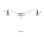
- FIG. 2 provides a diagram of an example two-path channel model for a UE that is moving at a high speed.
- a UE may be located in an automobile 202 that is traveling along a high way between the RRH 204 and the RRH 206 of an SFN that is serving the UE.
- f 1 ⁇ f 2 .
- the UE 202 experiences two opposite Doppler shifts from the RRH 204 and the RRH 206 .
- a channel to the UE 202 can appear as a superposition of h 1 and h 2 .
- Legacy channel estimation handles this superposition of signals, though, as a single channel propagation from one transmission point.
- the carrier frequency used is 3 gigahertz (GHz) and the automobile 202 were replaced by a high speed train traveling at speed of 350 kilometers per hour (km/h)
- the Doppler shift would be approximately 800 hertz (Hz) for each of the RRHs 204 and 206 . Since the Doppler shifts for the RRHs 204 and 206 are in opposite directions, the Doppler spread between the RRHs 204 and 206 can be up to 1.6 kilohertz (KHz). A Doppler spread of this magnitude is significant if 15 KHz subcarrier spacing is assumed.
- the UE can compensate for the Doppler shift by manipulating the phase in the frequency domain.
- the Doppler shift can be handled as a frequency offset.
- a channel estimator can address Doppler spread using timing domain interpolation. In either case, though, the UE that is the receiver can execute compensation based on separately estimated channel parameters for each transmission point. Without such separately estimated channel parameters, there is not an immediate way for the UE to make such a compensation.
- FIG. 3 provides an example table 300 in which UERS antenna ports are coded by orthogonal codes.
- the RRHs 204 and 206 in FIG. 2 can transmit according to the following equation:
- Y DMRS signifies received DMRS signals in frequency domain
- N RRHset is the number of RRHs in the deployment sustaining code orthogonality.
- P is a precoder in each of the RRHs 204 and 206
- H is a MIMO channel
- s DMRS is a DMRS reference sequence vector over multiple consecutive time-domain symbols
- ‘ ⁇ ’ notation means a Hadamard product between vectors
- n is an Additive White Gaussian Noise (AWGN) vector over the Orthogonal Frequency Division Multiplexing (OFDM) symbols.
- AWGN Additive White Gaussian Noise
- each of the RRHs 204 , 206 utilizes an identical scrambling seed (such as nSCID, PCID, or VCID values), then identical DMRS reference sequences s DMRS are transmitted from the RRHs 204 , 206 and DMRS APs will be orthogonal between UERS APs. If the RRHs 204 , 206 utilize different scrambling seeds, then the s DMRS-RRH i is also generated differently in each RRH I and the S DMRS-RRH i and S DMRS-RRH k (i ⁇ k) are semi-orthogonal by the pseudo random sequence property.
- an identical scrambling seed such as nSCID, PCID, or VCID values
- UERS antenna ports can be demodulated per an AP as
- H DMRS - RRH i 1 N code ⁇ Y DMRS ⁇ [ w _ p - 7 + ( i ⁇ ⁇ modN RRHset ) ⁇ s _ DMRS ] H
- N code is a length of an orthogonal codeword
- H is the Hermetian transform.
- the receiver e.g., UE
- can receive Y DMRS Y DMRS-RRH1 +Y DMRS-RRH 2 + n , (i.e., that is (number of RX) ⁇ (2 DMRS symbols)), and can demodulate according to the equations:
- RS symbols e.g., DMRS symbols
- parameter estimation for each AP is possible.
- An estimator applied by the receiver can investigate the correlations between time symbols or between frequency symbols as shown in FIG. 4 .
- FIG. 4 provides an example mapping 400 that illustrates correlations between time symbols and correlations between frequency symbols.
- Units of the horizontal axis can represent time, while units of the vertical axis can represent frequency.
- the resource element that is at row 406 and at column 402 can have a time-symbol correlation with the resource element that is at row 406 and at column 404 .
- the resource element that is at row 406 and at column 402 can have a frequency-symbol correlation with the resource element that is at row 408 and at column 402 .
- a legacy UE takes an average over samples of all APs for correlation computation, since it assumes that channel characteristics are identical among APs.
- a UE can separately compute the correlation for different channel characteristics on a per-RRH link basis.
- a UE can also be configured to apply estimated channel parameters for RRHs separately in cell-specific reference signals (CRS)-based PDSCH TMs.
- HST RRHs can be configured to transmit data (PDSCH) signals in an SFN manner.
- the cell-specific reference signals (CRS) transmissions can be done in a non-SFN manner.
- different resource elements (REs) can be used for CRS transmissions from different RRHs.
- the CRS REs for the given Cell ID can be split into several subsets (e.g., 2 subsets) of REs in a Physical resource Block (PRB) pair.
- PRB Physical resource Block
- Each RRH can transmit signals on different REs.
- the UE can estimate the channel characteristics for each RRH using information about the subset of REs used for each transmission.
- the information can be conveyed via RRC signaling to the UE or can be pre-configured.
- different RRHs may have different Physical Cell IDs for the CRS transmissions. In this case, the UE may have information about those IDs and may use this information to attempt to estimate a respective channel for each RRH independently.
- FIG. 5 provides a conceptual diagram 500 of channel parameter estimations and compensation per an antenna port (AP) and a MIMO layer.
- AP antenna port
- MIMO layer There are various methods that may be applied to estimate delay shift, Doppler shift, delay spread, Doppler spread, and channel gain.
- Reference Signal (RS) demodulation samples that are on a per-AP basis can be used by a delay shift estimator, a Doppler shift estimator, a delay spread estimator, a Doppler spread estimator, and a Signal-to-Interference-plus-noise Ratio estimator.
- Each of the estimators can provide a corresponding estimate to compensation blocks, such as a frequency synchronization block, a timing synchronization block, a MIMO channel estimator (CE) block, and an automatic gain controller (AGC) block.
- CE MIMO channel estimator
- AGC automatic gain controller
- Different channel interpolation filters can be applied to each signal corresponding to a respective AP (and therefore RRH).
- some channel parameters can be estimated globally over multiple APs rather than on a per-AP basis.
- compensation and channel estimation can be computed on a per-AP basis or globally over multiple APs.
- H i P i s data is the target signal from RRH i .
- Y _ ⁇ ⁇ i nRRH ⁇ ⁇ H i ⁇ P i ⁇ s data + n
- ⁇ i nRRH H i P i s data is the target signal
- n is the noise.
- a third option includes a mixed form of the first and second options.
- Y Data signifies received data signals in frequency domain
- nRRH is the number of RRHs in the deployment from which signals are being sent
- n is noise.
- P i and P j are precoders for RRHs at indices i and j, respectively.
- H i and H j are MIMO channels for RRHs at indices i and j, respectively.
- the first option it is assumed that only one RRH channel path is valid and other signals are regarded as interference and noise. This option provides benefit when one path has a significantly strong propagation power than other paths and the other paths are too negligible to cause a large channel estimation error.
- the second option provides benefit when more than one path has a significant valid propagation.
- Detection methods can be applied based on the first option, the second option, or a model that is a combination of the first and second options. Interference rejection methods also can be applied.
- FIG. 6 illustrates functionality 600 of User Equipment (UE) in accordance with an example.
- the functionality 600 can be implemented as a method or the functionality can be executed as instructions on a machine (e.g., by one or more processors), where the instructions are included on at least one computer-readable storage medium (e.g., a transitory or non-transitory computer-readable storage medium).
- UE User Equipment
- the functionality 600 can include identifying a first physical-channel transmission, received at the UE, that was sent from a first Remote Radio Head (RRH) using a first Antenna Port (AP) in a Single Frequency Network (SFN), wherein the first physical-channel transmission includes a payload assigned by the SFN and includes a first Reference Signal (RS).
- the payload can be a Physical Downlink Shared Channel (PDSCH) payload or an enhanced Physical Downlink Control Channel (ePDCCH) payload.
- PDSCH Physical Downlink Shared Channel
- ePDCCH enhanced Physical Downlink Control Channel
- the functionality 600 can include identifying a second physical-channel transmission, received at the UE, that was sent from a second RRH using a second AP in the SFN, wherein the second physical-channel transmission includes the payload assigned by the SFN and includes a second RS.
- the first RS and the second RS can be Demodulation Reference Signals (DMRSs), UE-specific Demodulation Reference Signals (UERSs), or Cell-specific Demodulation Reference Signals (CRSs).
- DMRSs Demodulation Reference Signals
- UERSs UE-specific Demodulation Reference Signals
- CRSs Cell-specific Demodulation Reference Signals
- the functionality 600 can include demodulating the first RS based on the first AP.
- the first RS can be demodulated based on a first scrambling sequence corresponding to the first AP.
- the functionality 600 can include demodulating the second RS based on the second AP.
- the second RS can be demodulated based on a second scrambling sequence corresponding to the second AP
- the functionality 600 can include processing a Radio Resource Control (RRC) indicator received from an evolved Node B (eNB), the RRC indicator indicating that the UE is to calculate the one or more channel parameters for the first physical-channel transmission and the one or more channel parameters for the second physical-channel transmission separately based on a motion pattern of the UE.
- RRC Radio Resource Control
- the functionality 600 can include estimating one or more channel parameters for the first physical-channel transmission based on the first RS.
- the functionality 600 can include estimating one or more channel parameters for the second physical-channel transmission based on the second RS.
- the one or channel parameters for the first physical-channel transmission or the one or more channel parameters for the second physical-channel transmission can include at least one of: a delay shift, a Doppler shift, a delay spread, a Doppler spread, or a channel gain.
- the functionality 600 can also include performing Multiple Input Multiple Output (MIMO) demodulation processing on the first physical-channel transmission using the one or more channel parameters for the first physical-channel transmission to form a first demodulated signal for the payload.
- MIMO Multiple Input Multiple Output
- the functionality 600 can include performing MIMO demodulation processing on the second physical-channel transmission using the one or more channel parameters for the second physical-channel transmission to form a second demodulated signal for the payload and combining the first demodulated signal for the payload and the second demodulated signal for the payload at a Quadrature Amplitude Modulation (QAM) symbol level or at a soft bit level to determine the payload with increased accuracy.
- QAM Quadrature Amplitude Modulation
- the functionality 600 can include demodulating the payload using at least one of: the one or more channel parameters for the first physical-channel transmission or the one or more channel parameters for the second physical-channel transmission.
- the functionality 600 can include determining that a channel link to the first RRH has a higher received power level than a channel link to the second RRH based on the one or more channel parameters for the first physical-channel transmission and based on the one or more channel parameters for the second physical-channel transmission; suppressing the channel link to the second RRH as interference; and demodulating the payload using the one or more channel parameters for the first physical-channel transmission.
- FIG. 7 illustrates functionality 700 of cellular base station (e.g., an evolved Node B) in accordance with an example.
- the functionality 700 can be implemented as a method or the functionality can be executed as instructions on a machine (e.g., by one or more processors), where the instructions are included on at least one computer-readable storage medium (e.g., a transitory or non-transitory computer-readable storage medium).
- a computer-readable storage medium e.g., a transitory or non-transitory computer-readable storage medium.
- the functionality 700 can include identifying a User Equipment (UE) that is moving through a coverage area of the SFN and is likely to experience unequal Doppler shifts for wireless transmissions sent from different transmission points in the SFN.
- UE User Equipment
- the functionality 700 can include sending a Radio Resource Control (RRC) indicator to the UE, the RRC indicator indicating that the UE is to estimate one or more channel parameters for the first physical-channel transmission and one or more channel parameters for the second physical-channel transmission separately.
- RRC Radio Resource Control
- the functionality 700 can include sending, via a first Remote Radio Head (RRH) using a first Antenna Port (AP) in the SFN, a first physical-channel transmission to the UE, wherein the first physical-channel transmission includes a payload assigned by the SFN and includes a first Reference Signal (RS).
- RRH Remote Radio Head
- AP Antenna Port
- RS Reference Signal
- the functionality 700 can include sending, via a second Remote Radio Head (RRH) using a second Antenna Port (AP) in the SFN, a second physical-channel transmission to the UE, wherein the second physical-channel transmission includes a the payload assigned by the SFN and includes a second Reference Signal (RS).
- the payload can be a Physical Downlink Shared Channel (PDSCH) payload or an enhanced Physical Downlink Control Channel (ePDCCH) payload.
- the first RS and the second RS can be Demodulation Reference Signals (DMRSs), UE-specific Demodulation Reference Signals (UERSs) or Cell-specific Demodulation Reference Signals (CRSs).
- DMRSs Demodulation Reference Signals
- UERSs UE-specific Demodulation Reference Signals
- CRSs Cell-specific Demodulation Reference Signals
- FIG. 8 provides an example illustration of a mobile device, such as a user equipment (UE), a mobile station (MS), a mobile wireless device, a mobile communication device, a tablet, a handset, a CIoT device, or other type of wireless device.
- the mobile device can include one or more antennas configured to communicate with a node, macro node, low power node (LPN), or, transmission station, such as a base station (BS), an evolved Node B (eNB), a baseband processing unit (BBU), a remote radio head (RRH), a remote radio equipment (RRE), a relay station (RS), a radio equipment (RE), or other type of wireless wide area network (WWAN) access point.
- BS base station
- eNB evolved Node B
- BBU baseband processing unit
- RRH remote radio head
- RRE remote radio equipment
- RS relay station
- RE radio equipment
- the mobile device can be configured to communicate using at least one wireless communication standard such as, but not limited to, 3GPP LTE, WiMAX, High Speed Packet Access (HSPA), Bluetooth, and WiFi.
- the mobile device can communicate using separate antennas for each wireless communication standard or shared antennas for multiple wireless communication standards.
- the mobile device can communicate in a wireless local area network (WLAN), a wireless personal area network (WPAN), and/or a WWAN.
- WLAN wireless local area network
- WPAN wireless personal area network
- WWAN wireless wide area network
- the mobile device can also comprise a wireless modem.
- the wireless modem can comprise, for example, a wireless radio transceiver and baseband circuitry (e.g., a baseband processor).
- the wireless modem can, in one example, modulate signals that the mobile device transmits via the one or more antennas and demodulate signals that the mobile device receives via the one or more antennas.
- the mobile device can include a storage medium.
- the storage medium can be associated with and/or communication with the application processor, the graphics processor, the display, the non-volatile memory port, and/or internal memory.
- the application processor and graphics processor are storage mediums.
- FIG. 8 also provides an illustration of a microphone and one or more speakers that can be used for audio input and output from the mobile device.
- the display screen can be a liquid crystal display (LCD) screen, or other type of display screen such as an organic light emitting diode (OLED) display.
- the display screen can be configured as a touch screen.
- the touch screen can use capacitive, resistive, or another type of touch screen technology.
- An application processor and a graphics processor can be coupled to internal memory to provide processing and display capabilities.
- a non-volatile memory port can also be used to provide data input/output options to a user.
- the non-volatile memory port can also be used to expand the memory capabilities of the mobile device.
- a keyboard can be integrated with the mobile device or wirelessly connected to the wireless device to provide additional user input.
- a virtual keyboard can also be provided using the touch screen.
- FIG. 9 provides an example illustration of a user equipment (UE) device 900 , such as a wireless device, a mobile station (MS), a mobile wireless device, a mobile communication device, a tablet, a handset, a CIoT device, or other type of wireless device.
- the UE device 900 can include one or more antennas configured to communicate with a node or transmission station, such as a base station (BS), an evolved Node B (eNB), a baseband unit (BBU), a remote radio head (RRH), a remote radio equipment (RRE), a relay station (RS), a radio equipment (RE), a remote radio unit (RRU), a central processing module (CPM), or other type of wireless wide area network (WWAN) access point.
- BS base station
- eNB evolved Node B
- BBU baseband unit
- RRH remote radio head
- RRE remote radio equipment
- RS relay station
- RE radio equipment
- RRU remote radio unit
- CCM central processing module
- the UE device 900 can be configured to communicate using at least one wireless communication standard such as, but not limited to, 3GPP LTE, WiMAX, High Speed Packet Access (HSPA), Bluetooth, and WiFi.
- the UE device 900 can communicate using separate antennas for each wireless communication standard or shared antennas for multiple wireless communication standards.
- the UE device 900 can communicate in a wireless local area network (WLAN), a wireless personal area network (WPAN), and/or a WWAN.
- WLAN wireless local area network
- WPAN wireless personal area network
- WWAN wireless wide area network
- the UE device 900 may include application circuitry 902 , baseband circuitry 904 , Radio Frequency (RF) circuitry 906 , front-end module (FEM) circuitry 908 and one or more antennas 910 , coupled together at least as shown.
- application circuitry 902 may include application circuitry 902 , baseband circuitry 904 , Radio Frequency (RF) circuitry 906 , front-end module (FEM) circuitry 908 and one or more antennas 910 , coupled together at least as shown.
- RF Radio Frequency
- FEM front-end module
- the application circuitry 902 may include one or more application processors.
- the application circuitry 902 may include circuitry such as, but not limited to, one or more single-core or multi-core processors.
- the processor(s) may include any combination of general-purpose processors and dedicated processors (e.g., graphics processors, application processors, etc.).
- the processors may be coupled with and/or may include memory/storage (e.g., storage medium 912 ) and may be configured to execute instructions stored in the memory/storage (e.g., storage medium 912 ) to enable various applications and/or operating systems to run on the system.
- the baseband circuitry 904 may include circuitry such as, but not limited to, one or more single-core or multi-core processors.
- the baseband circuitry 904 may include one or more baseband processors and/or control logic to process baseband signals received from a receive signal path of the RF circuitry 906 and to generate baseband signals for a transmit signal path of the RF circuitry 906 .
- Baseband processing circuitry 904 may interface with the application circuitry 902 for generation and processing of the baseband signals and for controlling operations of the RF circuitry 906 .
- the baseband circuitry 904 may include a second generation (2G) baseband processor 904 a , third generation (3G) baseband processor 904 b , fourth generation (4G) baseband processor 904 c , and/or other baseband processor(s) 904 d for other existing generations, generations in development or to be developed in the future (e.g., fifth generation (5G), 6G, etc.).
- the baseband circuitry 904 e.g., one or more of baseband processors 904 a - d
- the radio control functions may include, but are not limited to, signal modulation/demodulation, encoding/decoding, radio frequency shifting, etc.
- modulation/demodulation circuitry of the baseband circuitry 904 may include Fast-Fourier Transform (FFT), precoding, and/or constellation mapping/demapping functionality.
- encoding/decoding circuitry of the baseband circuitry 904 may include convolution, tail-biting convolution, turbo, Viterbi, and/or Low Density Parity Check (LDPC) encoder/decoder functionality.
- FFT Fast-Fourier Transform
- encoding/decoding circuitry of the baseband circuitry 904 may include convolution, tail-biting convolution, turbo, Viterbi, and/or Low Density Parity Check (LDPC) encoder/decoder functionality.
- LDPC Low Density Parity Check
- the baseband circuitry 904 may include elements of a protocol stack such as, for example, elements of an evolved universal terrestrial radio access network (EUTRAN) protocol including, for example, physical (PHY), media access control (MAC), radio link control (RLC), packet data convergence protocol (PDCP), and/or radio resource control (RRC) elements.
- EUTRAN evolved universal terrestrial radio access network
- a central processing unit (CPU) 904 e of the baseband circuitry 904 may be configured to run elements of the protocol stack for signaling of the PHY, MAC, RLC, PDCP and/or RRC layers.
- the baseband circuitry may include one or more audio digital signal processor(s) (DSP) 904 f
- the audio DSP(s) 904 f may include elements for compression/decompression and echo cancellation and may include other suitable processing elements in other embodiments.
- Components of the baseband circuitry may be suitably combined in a single chip, a single chipset, or disposed on a same circuit board in some embodiments.
- some or all of the constituent components of the baseband circuitry 904 and the application circuitry 902 may be implemented together such as, for example, on a system on a chip (SOC).
- SOC system on a chip
- the baseband circuitry 904 may provide for communication compatible with one or more radio technologies.
- the baseband circuitry 904 may support communication with an evolved universal terrestrial radio access network (EUTRAN) and/or other wireless metropolitan area networks (WMAN), a wireless local area network (WLAN), a wireless personal area network (WPAN).
- EUTRAN evolved universal terrestrial radio access network
- WMAN wireless metropolitan area networks
- WLAN wireless local area network
- WPAN wireless personal area network
- multi-mode baseband circuitry Embodiments in which the baseband circuitry 904 is configured to support radio communications of more than one wireless protocol.
- the RF circuitry 906 may enable communication with wireless networks using modulated electromagnetic radiation through a non-solid medium.
- the RF circuitry 906 may include switches, filters, amplifiers, etc. to facilitate the communication with the wireless network.
- RF circuitry 906 may include a receive signal path which may include circuitry to down-convert RF signals received from the FEM circuitry 908 and provide baseband signals to the baseband circuitry 904 .
- RF circuitry 906 may also include a transmit signal path which may include circuitry to up-convert baseband signals provided by the baseband circuitry 904 and provide RF output signals to the FEM circuitry 908 for transmission.
- the RF circuitry 906 may include a receive signal path and a transmit signal path.
- the receive signal path of the RF circuitry 906 may include mixer circuitry 906 a , amplifier circuitry 906 b and filter circuitry 906 c .
- the transmit signal path of the RF circuitry 906 may include filter circuitry 906 c and mixer circuitry 906 a .
- RF circuitry 906 may also include synthesizer circuitry 906 d for synthesizing a frequency for use by the mixer circuitry 906 a of the receive signal path and the transmit signal path.
- the mixer circuitry 906 a of the receive signal path may be configured to down-convert RF signals received from the FEM circuitry 908 based on the synthesized frequency provided by synthesizer circuitry 906 d .
- the amplifier circuitry 906 b may be configured to amplify the down-converted signals and the filter circuitry 906 c may be a low-pass filter (LPF) or band-pass filter (BPF) configured to remove unwanted signals from the down-converted signals to generate output baseband signals.
- Output baseband signals may be provided to the baseband circuitry 904 for further processing.
- the output baseband signals may be zero-frequency baseband signals, although other types of baseband signals may be used.
- mixer circuitry 906 a of the receive signal path may comprise passive mixers, although the scope of the embodiments is not limited in this respect.
- the mixer circuitry 906 a of the transmit signal path may be configured to up-convert input baseband signals based on the synthesized frequency provided by the synthesizer circuitry 906 d to generate RF output signals for the FEM circuitry 908 .
- the baseband signals may be provided by the baseband circuitry 904 and may be filtered by filter circuitry 906 c .
- the filter circuitry 906 c may include a low-pass filter (LPF), although the scope of the embodiments is not limited in this respect.
- LPF low-pass filter
- the mixer circuitry 906 a of the receive signal path and the mixer circuitry 906 a of the transmit signal path may include two or more mixers and may be arranged for quadrature down-conversion and/or up-conversion respectively.
- the mixer circuitry 906 a of the receive signal path and the mixer circuitry 906 a of the transmit signal path may include two or more mixers and may be arranged for image rejection (e.g., Hartley image rejection).
- the mixer circuitry 906 a of the receive signal path and the mixer circuitry 906 a may be arranged for direct down-conversion and/or direct up-conversion, respectively.
- the mixer circuitry 906 a of the receive signal path and the mixer circuitry 906 a of the transmit signal path may be configured for super-heterodyne operation.
- the output baseband signals and the input baseband signals may be analog baseband signals, although the scope of the embodiments is not limited in this respect.
- the output baseband signals and the input baseband signals may be digital baseband signals.
- the RF circuitry 906 may include analog-to-digital converter (ADC) and digital-to-analog converter (DAC) circuitry and the baseband circuitry 904 may include a digital baseband interface to communicate with the RF circuitry 906 .
- ADC analog-to-digital converter
- DAC digital-to-analog converter
- a separate radio IC circuitry may be provided for processing signals for each spectrum, although the scope of the embodiments is not limited in this respect.
- the synthesizer circuitry 906 d may be a fractional-N synthesizer or a fractional N/N+1 synthesizer, although the scope of the embodiments is not limited in this respect as other types of frequency synthesizers may be suitable.
- synthesizer circuitry 906 d may be a delta-sigma synthesizer, a frequency multiplier, or a synthesizer comprising a phase-locked loop with a frequency divider.
- the synthesizer circuitry 906 d may be configured to synthesize an output frequency for use by the mixer circuitry 906 a of the RF circuitry 906 based on a frequency input and a divider control input. In some embodiments, the synthesizer circuitry 906 d may be a fractional N/N+1 synthesizer.
- frequency input may be provided by a voltage controlled oscillator (VCO), although other types of devices may provide the frequency input.
- VCO voltage controlled oscillator
- Divider control input may be provided by either the baseband circuitry 904 or the applications processor 902 depending on the desired output frequency.
- a divider control input (e.g., N) may be determined from a look-up table based on a channel indicated by the applications processor 902 .
- Synthesizer circuitry 906 d of the RF circuitry 906 may include a divider, a delay-locked loop (DLL), a multiplexer and a phase accumulator.
- the divider may be a dual modulus divider (DMD) and the phase accumulator may be a digital phase accumulator (DPA).
- the DMD may be configured to divide the input signal by either N or N+1 (e.g., based on a carry out) to provide a fractional division ratio.
- the DLL may include a set of cascaded, tunable, delay elements, a phase detector, a charge pump and a D-type flip-flop.
- the delay elements may be configured to break a VCO period up into Nd equal packets of phase, where Nd is the number of delay elements in the delay line.
- Nd is the number of delay elements in the delay line.
- synthesizer circuitry 906 d may be configured to generate a carrier frequency as the output frequency, while in other embodiments, the output frequency may be a multiple of the carrier frequency (e.g., twice the carrier frequency, four times the carrier frequency) and used in conjunction with quadrature generator and divider circuitry to generate multiple signals at the carrier frequency with multiple different phases with respect to each other.
- the output frequency may be a LO frequency (fLO).
- the RF circuitry 906 may include an IQ/polar converter.
- FEM circuitry 908 may include a receive signal path which may include circuitry configured to operate on RF signals received from one or more antennas 910 , amplify the received signals and provide the amplified versions of the received signals to the RF circuitry 906 for further processing.
- FEM circuitry 908 may also include a transmit signal path which may include circuitry configured to amplify signals for transmission provided by the RF circuitry 906 for transmission by one or more of the one or more antennas 910 .
- the FEM circuitry 908 may include a TX/RX switch to switch between transmit mode and receive mode operation.
- the FEM circuitry may include a receive signal path and a transmit signal path.
- the receive signal path of the FEM circuitry may include a low-noise amplifier (LNA) to amplify received RF signals and provide the amplified received RF signals as an output (e.g., to the RF circuitry 906 ).
- LNA low-noise amplifier
- the transmit signal path of the FEM circuitry 908 may include a power amplifier (PA) to amplify input RF signals (e.g., provided by RF circuitry 906 ), and one or more filters to generate RF signals for subsequent transmission (e.g., by one or more of the one or more antennas 910 .
- PA power amplifier
- the UE device 900 may include additional elements such as, for example, memory/storage, display (e.g., touch screen), camera, antennas, keyboard, microphone, speakers, sensor, and/or input/output (I/O) interface.
- display e.g., touch screen
- I/O input/output
- FIG. 10 illustrates a diagram 1000 of a node 1010 (e.g., eNB and/or a Serving GPRS Support Node) and a wireless device 1020 (e.g., UE) in accordance with an example.
- the node can include a base station (BS), a Node B (NB), an evolved Node B (eNB), a baseband unit (BBU), a remote radio head (RRH), a remote radio equipment (RRE), a remote radio unit (RRU), or a central processing module (CPM).
- the node can be a Serving GPRS Support Node.
- the node 1010 can include a node device 1012 .
- the node device 1012 or the node 1010 can be configured to communicate with the wireless device 1020 .
- the node device 1012 can be configured to implement technologies described herein.
- the node device 1012 can include a processing module 1014 and a transceiver module 1016 .
- the node device 1012 can include the transceiver module 1016 and the processing module 1014 forming a circuitry for the node 1010 .
- the transceiver module 1016 and the processing module 1014 can form a circuitry of the node device 1012 .
- the processing module 1014 can include one or more processors and memory.
- the processing module 1022 can include one or more application processors.
- the transceiver module 1016 can include a transceiver and one or more processors and memory. In some examples, components of the transceiver module 1316 can be included in separate devices. For example, selected components of the transceiver module 1316 may be located in a cloud radio access network (C-RAN). In one embodiment, the transceiver module 1016 can include a baseband processor. In some examples, components of the transceiver module 1016 can be included in separate devices.
- C-RAN cloud radio access network
- the wireless device 1020 can include a transceiver module 1024 and a processing module 1022 .
- the processing module 1022 can include one or more processors and memory. In one embodiment, the processing module 1022 can include one or more application processors.
- the transceiver module 1024 can include a transceiver and one or more processors and memory. In one embodiment, the transceiver module 1024 can include a baseband processor.
- the wireless device 1020 can be configured to implement technologies described herein.
- the node 1010 and the wireless devices 1020 can also include one or more storage mediums, such as the transceiver module 1016 , 1024 and/or the processing module 1014 , 1022 .
- Example 1 includes an apparatus of a user equipment (UE) comprising one or more processors and memory configured to: identify a first physical-channel transmission, received at the UE, that was sent from a first Remote Radio Head (RRH) using a first Antenna Port (AP) in a Single Frequency Network (SFN), wherein the first physical-channel transmission includes a payload assigned by the SFN and includes a first Reference Signal (RS); identify a second physical-channel transmission, received at the UE, that was sent from a second RRH using a second AP in the SFN, wherein the second physical-channel transmission includes the payload assigned by the SFN and includes a second RS; demodulate the first RS based on the first AP; demodulate the second RS based on the second AP; estimate one or more channel parameters for the first physical-channel transmission based on the first RS; estimate one or more channel parameters for the second physical-channel transmission based on the second RS; and demodulate the payload using at least one of: the one
- example 2 the subject matter of example 1 or any of the examples described herein may further include that the one or more processors and memory are further configured to: determine that a channel link to the first RRH has a higher received power level than a channel link to the second RRH based on the one or more channel parameters for the first physical-channel transmission and based on the one or more channel parameters for the second physical-channel transmission; suppress the channel link to the second RRH as interference; and demodulate the payload using the one or more channel parameters for the first physical-channel transmission.
- example 3 the subject matter of example 1 or any of the examples described herein may further include that the one or more processors and memory are further configured to: perform Multiple Input Multiple Output (MIMO) demodulation processing on the first physical-channel transmission using the one or more channel parameters for the first physical-channel transmission to form a first demodulated signal for the payload; perform MIMO demodulation processing on the second physical-channel transmission using the one or more channel parameters for the second physical-channel transmission to form a second demodulated signal for the payload; and combine the first demodulated signal for the payload and the second demodulated signal for the payload at a Quadrature Amplitude Modulation (QAM) symbol level to determine the payload with increased accuracy.
- MIMO Multiple Input Multiple Output
- example 4 the subject matter of example 1, 3, or any of the examples described herein may further include that the one or more processors and memory are further configured to: perform Multiple Input Multiple Output (MIMO) demodulation processing on the first physical-channel transmission using the one or more channel parameters for the first physical-channel transmission to form a first demodulated signal for the payload; perform MIMO demodulation processing on the second physical-channel transmission using the one or more channel parameters for the second physical-channel transmission to form a second demodulated signal for the payload; and combine the first demodulated signal for the payload and the second demodulated signal for the payload at a soft bit level to determine the payload with increased accuracy.
- MIMO Multiple Input Multiple Output
- the subject matter of example 1, 2, 3, 4, or any of the examples described herein may further include that the first RS and the second RS are Demodulation Reference Signals (DMRSs), UE-specific Demodulation Reference Signals (UERSs), or Cell-specific Demodulation Reference Signals (CRSs).
- DMRSs Demodulation Reference Signals
- UERSs UE-specific Demodulation Reference Signals
- CRSs Cell-specific Demodulation Reference Signals
- example 6 the subject matter of example 1, 2, 3, 4, 5, or any of the examples described herein may further include that the one or more processors and memory are further configured to: demodulate the first RS based on a first scrambling sequence corresponding to the first AP; and demodulate the second RS based on a second scrambling sequence corresponding to the second AP.
- example 7 the subject matter of example 1, 2, 3, 4, 5, 6, or any of the examples described herein may further include that the payload is a Physical Downlink Shared Channel (PDSCH) payload or an enhanced Physical Downlink Control Channel (ePDCCH) payload.
- PDSCH Physical Downlink Shared Channel
- ePDCCH enhanced Physical Downlink Control Channel
- example 8 the subject matter of example 1, 2, 3, 4, 5, 6, 7, or any of the examples described herein may further include that the one or channel parameters for the first physical-channel transmission or the one or more channel parameters for the second physical-channel transmission include at least one of: a delay shift, a Doppler shift, a delay spread, a Doppler spread, or a channel gain.
- example 9 the subject matter of example 1, 2, 3, 4, 5, 6, 7, 8, or any of the examples described herein may further include that the one or more processors and memory are further configured to process a Radio Resource Control (RRC) indicator received from an evolved Node B (eNB), the RRC indicator indicating that the UE is to calculate the one or more channel parameters for the first physical-channel transmission and the one or more channel parameters for the second physical-channel transmission separately based on a motion pattern of the UE.
- RRC Radio Resource Control
- example 10 the subject matter of example 1, 2, 3, 4, 5, 6, 7, 8, 9, or any of the examples described herein may further include that the one or more processors include a baseband processor.
- Example 11 includes an apparatus of an evolved node B (eNB) in a Single Frequency Network (SFN), the apparatus comprising one or more processors and memory configured to: identify a User Equipment (UE) that is moving through a coverage area of the SFN and is likely to experience unequal Doppler shifts for wireless transmissions sent from different transmission points in the SFN; send, via a first Remote Radio Head (RRH) using a first Antenna Port (AP) in the SFN, a first physical-channel transmission to the UE, wherein the first physical-channel transmission includes a payload assigned by the SFN and includes a first Reference Signal (RS); and send, via a second Remote Radio Head (RRH) using a second Antenna Port (AP) in the SFN, a second physical-channel transmission to the UE, wherein the second physical-channel transmission includes a the payload assigned by the SFN and includes a second Reference Signal (RS).
- UE User Equipment
- AP Antenna Port
- RS Reference Signal
- the subject matter of example 11 or any of the examples described herein may further include that the first RS and the second RS are Demodulation Reference Signals (DMRSs), UE-specific Demodulation Reference Signals (UERSs) or Cell-specific Demodulation Reference Signals (CRSs).
- DMRSs Demodulation Reference Signals
- UERSs UE-specific Demodulation Reference Signals
- CRSs Cell-specific Demodulation Reference Signals
- example 13 the subject matter of example 11, 12, or any of the examples described herein may further include that the payload is a Physical Downlink Shared Channel (PDSCH) payload or an enhanced Physical Downlink Control Channel (ePDCCH) payload.
- PDSCH Physical Downlink Shared Channel
- ePDCCH enhanced Physical Downlink Control Channel
- example 14 the subject matter of example 11, 12, 13, or any of the examples described herein may further include that the one or more processors and memory are further configured to send a Radio Resource Control (RRC) indicator to the UE, the RRC indicator indicating that the UE is to estimate one or more channel parameters for the first physical-channel transmission and one or more channel parameters for the second physical-channel transmission separately.
- RRC Radio Resource Control
- Example 15 includes a computer-readable medium (that may be non-transitory) containing instructions thereon that, when executed by one or more processors, perform the following: identifying a first physical-channel transmission, received at the UE, that was sent from a first Remote Radio Head (RRH) using a first Antenna Port (AP) in a Single Frequency Network (SFN), wherein the first physical-channel transmission includes a payload and includes a first Reference Signal (RS); identifying a second physical-channel transmission, received at the UE, that was sent from a second RRH using a second AP in the SFN, wherein the second physical-channel transmission includes the payload and includes a second RS; demodulating the first RS based on the first AP; demodulating the second RS based on the second AP; estimating one or more channel parameters for the first physical-channel transmission based on the first RS; estimating one or more channel parameters for the second physical-channel transmission based on the second RS; and demodulating the payload
- example 16 the subject matter of example 15 or any of the examples described herein may further include that the computer-readable medium further contains instructions thereon that, when executed by the one or more processors, perform the following: determining that a channel link to the first RRH has a higher received power level than a channel link to the second RRH based on the one or more channel parameters for the first physical-channel transmission and based on the one or more channel parameters for the second physical-channel transmission; suppressing the channel link to the second RRH as interference; and demodulating the payload using the one or more channel parameters for the first physical-channel transmission.
- the computer-readable medium further contains instructions thereon that, when executed by the one or more processors, perform the following: determining that a channel link to the first RRH has a higher received power level than a channel link to the second RRH based on the one or more channel parameters for the first physical-channel transmission and based on the one or more channel parameters for the second physical-channel transmission; suppressing the channel link to the second RRH as interference;
- example 17 the subject matter of example 15 or any of the examples described herein may further include that the computer-readable medium further contains instructions thereon that, when executed by the one or more processors, perform the following: performing Multiple Input Multiple Output (MIMO) demodulation processing on the first physical-channel transmission using the one or more channel parameters for the first physical-channel transmission to form a first demodulated signal for the payload; performing MIMO demodulation processing on the second physical-channel transmission using the one or more channel parameters for the second physical-channel transmission to form a second demodulated signal for the payload; and combining the first demodulated signal for the payload and the second demodulated signal for the payload at a Quadrature Amplitude Modulation (QAM) symbol level to determine the payload with increased accuracy.
- MIMO Multiple Input Multiple Output
- example 18 the subject matter of example 15 or any of the examples described herein may further include that the computer-readable medium further contains instructions thereon that, when executed by the one or more processors, perform the following: performing Multiple Input Multiple Output (MIMO) demodulation processing on the first physical-channel transmission using the one or more channel parameters for the first physical-channel transmission to form a first demodulated signal for the payload; performing MIMO demodulation processing on the second payload signal using the one or more channel parameters for the second physical-channel transmission to form a second demodulated signal for the payload; and combining the first demodulated signal for the payload and the second demodulated signal for the payload at a soft bit level to determine the payload with increased accuracy.
- MIMO Multiple Input Multiple Output
- the subject matter of example 15, 16, 17, 18, or any of the examples described herein may further include that the first RS and the second RS are Demodulation Reference Signals (DMRSs), UE-specific Demodulation Reference Signals (UERSs) or Cell-specific Demodulation Reference Signals (CRSs).
- DMRSs Demodulation Reference Signals
- UERSs UE-specific Demodulation Reference Signals
- CRSs Cell-specific Demodulation Reference Signals
- example 20 the subject matter of example 15, 16, 17, 18, 19, or any of the examples described herein may further include that the computer-readable medium further contains instructions thereon that, when executed by the one or more processors, perform the following: demodulating the first RS based on a first scrambling sequence corresponding to the first AP; and demodulating the second RS based on a second scrambling sequence corresponding to the second AP.
- the subject matter of example 15, 16, 17, 18, 19, 20, or any of the examples described herein may further include that the payload is a Physical Downlink Shared Channel (PDSCH) payload or an enhanced Physical Downlink Control Channel (ePDCCH) payload.
- PDSCH Physical Downlink Shared Channel
- ePDCCH enhanced Physical Downlink Control Channel
- the subject matter of example 15, 16, 17, 18, 19, 20, 21, or any of the examples described herein may further include that the one or channel parameters for the first physical-channel transmission or the one or more channel parameters for the second physical-channel transmission include at least one of: delay shift, Doppler shift, delay spread, Doppler spread, or channel gain.
- example 23 the subject matter of example example 15, 16, 17, 18, 19, 20, 21, 22, or any of the examples described herein may further include that the computer-readable medium further contains instructions thereon that, when executed by the one or more processors, perform the following: receiving, via the one or more antennas at the UE, a Radio Resource Control (RRC) indicator from an evolved Node B (eNB), the RRC indicator indicating that the UE is to calculate the one or more channel parameters for the first physical-channel transmission and the one or more channel parameters for the second physical-channel transmission separately based on a motion pattern of the UE.
- RRC Radio Resource Control
- Example 24 includes a means for receiving a payload in a Single Frequency Network (SFN), the means comprising: a means for identifying a first physical-channel transmission, received at the UE, that was sent from a first Remote Radio Head (RRH) using a first Antenna Port (AP) in a Single Frequency Network (SFN), wherein the first physical-channel transmission includes a payload and includes a first Reference Signal (RS); a means for identifying a second physical-channel transmission, received at the UE, that was sent from a second RRH using a second AP in the SFN, wherein the second physical-channel transmission includes the payload and includes a second RS; a means for demodulating the first RS based on the first AP; a means for demodulating the second RS based on the second AP; a means for estimating one or more channel parameters for the first physical-channel transmission based on the first RS; a means for estimating one or more channel parameters for the second physical-channel transmission
- example 25 the subject matter of example 24 or any of the examples described herein may further comprise: a means for determining that a channel link to the first RRH has a higher received power level than a channel link to the second RRH based on the one or more channel parameters for the first physical-channel transmission and based on the one or more channel parameters for the second physical-channel transmission; a means for suppressing the channel link to the second RRH as interference; and a means for demodulating the payload using the one or more channel parameters for the first physical-channel transmission.
- example 26 the subject matter of example 24 or any of the examples described herein may further comprise: a means for performing Multiple Input Multiple Output (MIMO) demodulation processing on the first physical-channel transmission using the one or more channel parameters for the first physical-channel transmission to form a first demodulated signal for the payload; a means for performing MIMO demodulation processing on the second physical-channel transmission using the one or more channel parameters for the second physical-channel transmission to form a second demodulated signal for the payload; and a means for combining the first demodulated signal for the payload and the second demodulated signal for the payload at a Quadrature Amplitude Modulation (QAM) symbol level to determine the payload with increased accuracy.
- MIMO Multiple Input Multiple Output
- example 27 the subject matter of example 24 or any of the examples described herein may further comprise: a means for performing Multiple Input Multiple Output (MIMO) demodulation processing on the first physical-channel transmission using the one or more channel parameters for the first physical-channel transmission to form a first demodulated signal for the payload; a means for performing MIMO demodulation processing on the second payload signal using the one or more channel parameters for the second physical-channel transmission to form a second demodulated signal for the payload; and a means for combining the first demodulated signal for the payload and the second demodulated signal for the payload at a soft bit level to determine the payload with increased accuracy.
- MIMO Multiple Input Multiple Output
- the subject matter of example 24[00111] or any of the examples described herein may further include that the first RS and the second RS are Demodulation Reference Signals (DMRSs), UE-specific Demodulation Reference Signals (UERSs) or Cell-specific Demodulation Reference Signals (CRSs).
- DMRSs Demodulation Reference Signals
- UERSs UE-specific Demodulation Reference Signals
- CRSs Cell-specific Demodulation Reference Signals
- example 29 the subject matter of example 24 or any of the examples described herein may further comprise: a means for demodulating the first RS based on a first scrambling sequence corresponding to the first AP; and a means for demodulating the second RS based on a second scrambling sequence corresponding to the second AP.
- example 30 the subject matter of example 24 or any of the examples described herein may further include that the payload is a Physical Downlink Shared Channel (PDSCH) payload or an enhanced Physical Downlink Control Channel (ePDCCH) payload.
- PDSCH Physical Downlink Shared Channel
- ePDCCH enhanced Physical Downlink Control Channel
- example 31 the subject matter of example 24 or any of the examples described herein may further include that the one or channel parameters for the first physical-channel transmission or the one or more channel parameters for the second physical-channel transmission include at least one of: delay shift, Doppler shift, delay spread, Doppler spread, or channel gain.
- example 32 the subject matter of example 24 or any of the examples described herein may further comprise: a means for receiving, via the one or more antennas at the UE, a Radio Resource Control (RRC) indicator from an evolved Node B (eNB), the RRC indicator indicating that the UE is to calculate the one or more channel parameters for the first physical-channel transmission and the one or more channel parameters for the second physical-channel transmission separately based on a motion pattern of the UE.
- RRC Radio Resource Control
- example 33 the subject matter of example 1 or any of the examples described herein may include that the one or more processors and memory are further configured to: perform Multiple Input Multiple Output (MIMO) demodulation processing on the first physical-channel transmission using the one or more channel parameters for the first physical-channel transmission to form a first demodulated signal for the payload; perform MIMO demodulation processing on the second physical-channel transmission using the one or more channel parameters for the second physical-channel transmission to form a second demodulated signal for the payload; and combine the first demodulated signal for the payload and the second demodulated signal for the payload at a Quadrature Amplitude Modulation (QAM) symbol level or a soft bit level to determine the payload with increased accuracy.
- MIMO Multiple Input Multiple Output
- example 34 the subject matter of example 15 or any of the examples described herein may include that the computer-readable medium further contains instructions thereon that, when executed by the one or more processors, perform the following: performing Multiple Input Multiple Output (MIMO) demodulation processing on the first physical-channel transmission using the one or more channel parameters for the first physical-channel transmission to form a first demodulated signal for the payload; performing MIMO demodulation processing on the second physical-channel transmission using the one or more channel parameters for the second physical-channel transmission to form a second demodulated signal for the payload; and combining the first demodulated signal for the payload and the second demodulated signal for the payload at a Quadrature Amplitude Modulation (QAM) symbol level or at a soft bit level to determine the payload with increased accuracy.
- MIMO Multiple Input Multiple Output
- Various techniques, or certain aspects or portions thereof, may take the form of program code (i.e., instructions) embodied in tangible media, such as floppy diskettes, compact disc-read-only memory (CD-ROMs), hard drives, transitory or non-transitory computer readable storage mediums, or any other machine-readable storage medium wherein, when the program code is loaded into and executed by a machine, such as a computer, the machine becomes an apparatus for practicing the various techniques.
- a non-transitory computer readable storage medium can be a computer readable storage medium that does not include signal.
- the computing device may include a processor, a storage medium readable by the processor (including volatile and non-volatile memory and/or storage elements), at least one input device, and at least one output device.
- the volatile and non-volatile memory and/or storage elements may be a random-access memory (RAM), erasable programmable read only memory (EPROM), flash drive, optical drive, magnetic hard drive, solid state drive, or other medium for storing electronic data.
- the node and wireless device may also include a transceiver module (i.e., transceiver), a counter module (i.e., counter), a processing module (i.e., processor), and/or a clock module (i.e., clock) or timer module (i.e., timer).
- a transceiver module i.e., transceiver
- a counter module i.e., counter
- a processing module i.e., processor
- a clock module i.e., clock
- timer module i.e., timer
- One or more programs that may implement or utilize the various techniques described herein may use an application programming interface (API), reusable controls, and the like. Such programs may be implemented in a high level procedural or object oriented programming language to communicate with a computer system. However, the program(s) may be implemented in assembly or machine language, if desired. In any case, the language may be a compiled or interpreted language, and combined with hardware implementations
- circuitry may refer to, be part of, or include an Application Specific Integrated Circuit (ASIC), an electronic circuit, a processor (shared, dedicated, or group), and/or memory (shared, dedicated, or group) that execute one or more software or firmware programs, a combinational logic circuit, and/or other suitable hardware components that provide the described functionality.
- ASIC Application Specific Integrated Circuit
- the circuitry may be implemented in, or functions associated with the circuitry may be implemented by, one or more software or firmware modules.
- circuitry may include logic, at least partially operable in hardware.
- the word “or” indicates an inclusive disjunction.
- the phrase “A or B” represents an inclusive disjunction of exemplary conditions A and B. Hence, “A or B” is false only if both condition A is false and condition B is false. When condition A is true and condition B is also true, “A or B” is also true. When condition A is true and condition B is false, “A or B” is true. When condition B is true and condition A is false, “A or B” is true. In other words, the term “or,” as used herein, should not be construed as an exclusive disjunction. The term “xor” is used where an exclusive disjunction is intended.
- processor can include general-purpose processors, specialized processors such as VLSI, FPGAs, and other types of specialized processors, as well as base-band processors used in transceivers to send, receive, and process wireless communications.
- modules can be implemented as a hardware circuit (e.g., an application-specific integrated circuit (ASIC)) comprising custom VLSI circuits or gate arrays, off-the-shelf semiconductors such as logic chips, transistors, or other discrete components.
- a module can also be implemented in programmable hardware devices such as field programmable gate arrays, programmable array logic, programmable logic devices or the like.
- Modules can also be implemented in software for execution by various types of processors.
- An identified module of executable code can, for instance, comprise one or more physical or logical blocks of computer instructions, which can, for instance, be organized as an object, procedure, or function. Nevertheless, the executables of an identified module do not have to be physically located together, but can comprise disparate instructions stored in different locations which, when joined logically together, comprise the module and achieve the stated purpose for the module.
- a module of executable code can be a single instruction, or many instructions, and can even be distributed over several different code segments, among different programs, and across several memory devices.
- operational data can be identified and illustrated herein within modules, and can be embodied in any suitable form and organized within any suitable type of data structure. The operational data can be collected as a single data set, or can be distributed over different locations including over different storage devices, and can exist, at least partially, merely as electronic signals on a system or network.
- the modules can be passive or active, including agents operable to perform desired functions.
- processor can include general purpose processors, specialized processors such as VLSI, FPGAs, and other types of specialized processors, as well as base band processors used in transceivers to send, receive, and process wireless communications.
Abstract
Description
h t=0 =h 1 ·e j·2π·f
h t=ΔT =h 1 ·e j·2π·f
where τ1 and τ2 are arrival timings from
where YDMRS signifies received DMRS signals in frequency domain, w is an orthogonal code between p=i and p=k from
where Ncode is a length of an orthogonal codeword and H is the Hermetian transform. For instance, assume an SFN deployment as shown in
Y DMRS-RRH1 =H 1 P 1[1 1]∘[s 1 ,s 2] for
Y DMRS-RRH2 =H 2 P 2[1 −1]∘[s 1 s 2] for
where [s1 s2] is loaded in two OFDM symbols in the time domain in the DMRS symbols. The receiver (e.g., UE) can receive YDMRS=YDMRS-RRH1+YDMRS-RRH 2+
Per these equations, demodulation of each antenna port can provide a separate channel estimate for each RRH transmission link.
In this first option, HiPisdata is the target signal from RRHi, and
is the interference plus noise. And a second option for a signal model is described by the equation
In this second option, Σi nRRH HiPisdata is the target signal, and n is the noise. A third option includes a mixed form of the first and second options. YData signifies received data signals in frequency domain, nRRH is the number of RRHs in the deployment from which signals are being sent, and n is noise. Pi and Pj are precoders for RRHs at indices i and j, respectively. Hi and Hj are MIMO channels for RRHs at indices i and j, respectively.
Claims (21)
Priority Applications (1)
| Application Number | Priority Date | Filing Date | Title |
|---|---|---|---|
| US15/772,473 US10516468B2 (en) | 2015-11-09 | 2016-04-01 | Mechanisms for single frequency networks in high-speed mobile scenarios |
Applications Claiming Priority (3)
| Application Number | Priority Date | Filing Date | Title |
|---|---|---|---|
| US201562253056P | 2015-11-09 | 2015-11-09 | |
| US15/772,473 US10516468B2 (en) | 2015-11-09 | 2016-04-01 | Mechanisms for single frequency networks in high-speed mobile scenarios |
| PCT/US2016/025734 WO2017082951A1 (en) | 2015-11-09 | 2016-04-01 | Mechanisms for single frequency networks in high-speed mobile scenarios |
Publications (2)
| Publication Number | Publication Date |
|---|---|
| US20180316409A1 US20180316409A1 (en) | 2018-11-01 |
| US10516468B2 true US10516468B2 (en) | 2019-12-24 |
Family
ID=55806775
Family Applications (1)
| Application Number | Title | Priority Date | Filing Date |
|---|---|---|---|
| US15/772,473 Active US10516468B2 (en) | 2015-11-09 | 2016-04-01 | Mechanisms for single frequency networks in high-speed mobile scenarios |
Country Status (3)
| Country | Link |
|---|---|
| US (1) | US10516468B2 (en) |
| CN (1) | CN108352865A (en) |
| WO (1) | WO2017082951A1 (en) |
Cited By (4)
| Publication number | Priority date | Publication date | Assignee | Title |
|---|---|---|---|---|
| US20210278520A1 (en) * | 2020-03-03 | 2021-09-09 | Cognitive Systems Corp. | Using High-Efficiency PHY Frames for Motion Detection |
| US11309957B2 (en) * | 2018-10-12 | 2022-04-19 | OQ Technology S.á.r.l. | Method and system for non-terrestrial cellular wireless communication networks |
| US11483721B1 (en) * | 2021-05-11 | 2022-10-25 | Nokia Technologies Oy | Apparatus and method for beam management |
| US20220357443A1 (en) * | 2021-05-07 | 2022-11-10 | Hyundai Mobis Co., Ltd. | Vehicle control system for detecting object and method thereof |
Families Citing this family (14)
| Publication number | Priority date | Publication date | Assignee | Title |
|---|---|---|---|---|
| KR102208310B1 (en) | 2015-02-11 | 2021-01-28 | 아이피컴 게엠베하 앤 코. 카게 | Method and device for constructing a single frequency network |
| US10841854B2 (en) * | 2016-08-04 | 2020-11-17 | Sony Corporation | Mobile telecommunications system transmission and reception points and methods for switching transmission and reception points between active and inactive states |
| CN109756904B (en) * | 2019-01-25 | 2022-02-01 | 哈尔滨工业大学(深圳) | 5G ultra-dense wireless access network deployment system and virtual cell updating method thereof |
| WO2020222285A1 (en) * | 2019-05-02 | 2020-11-05 | 株式会社Nttドコモ | User equipment and communication method |
| US20200374079A1 (en) * | 2019-08-15 | 2020-11-26 | Andrey Chervyakov | Single tap and single frequency network (sfn) high-speed train (hst) technologies |
| JP2023513291A (en) * | 2020-02-10 | 2023-03-30 | 華為技術有限公司 | Data transmission method and device |
| US20230344575A1 (en) * | 2020-03-13 | 2023-10-26 | Qualcomm Incorporated | Quasi co-location type for doppler pre-compensated reference signal |
| WO2021208069A1 (en) * | 2020-04-17 | 2021-10-21 | Qualcomm Incorporated | Csi feedback in high-speed train single frequency networks |
| CN113676295A (en) * | 2020-05-13 | 2021-11-19 | 中国移动通信有限公司研究院 | Reference signal receiving and sending method, terminal and network equipment |
| JP2023543621A (en) * | 2020-10-02 | 2023-10-17 | アップル インコーポレイテッド | Multiple-input multiple-output (MIMO) enhancement for high-speed movement |
| US20220141675A1 (en) * | 2020-11-05 | 2022-05-05 | Qualcomm Incorporated | Reference signal transmissions for multi-beam operation |
| KR20220151301A (en) * | 2021-05-06 | 2022-11-15 | 삼성전자주식회사 | Method and apparatus for data transmission in network cooperative communications |
| KR20220166656A (en) * | 2021-06-10 | 2022-12-19 | 삼성전자주식회사 | Method and apparatus for data transmission and reception in network cooperative communications |
| KR20220167157A (en) * | 2021-06-11 | 2022-12-20 | 삼성전자주식회사 | Method and apparatus for transmitting and receiving downlink control information and data in a wirelss communication system |
Citations (13)
| Publication number | Priority date | Publication date | Assignee | Title |
|---|---|---|---|---|
| US20080092194A1 (en) * | 2004-12-17 | 2008-04-17 | Electronics And Telecommunications Research Institute | Beam Combining and Hybrid Beam Selection Method for Improving Digital Broadcasting Reception Performance, and Digital Broadcasting Receiving Apparatus Using the Same |
| US20080268887A1 (en) * | 2007-02-26 | 2008-10-30 | Nokia Corporation | Multipoint data transmission |
| US20110317656A1 (en) * | 2009-12-23 | 2011-12-29 | Qualcomm Incorporated | Cluster-specific reference signals for communication systems with multiple transmission points |
| US20130044840A1 (en) * | 2010-05-10 | 2013-02-21 | Panasonic Corporation | Digital broadcast receiving apparatus and digital broadcast receiving method |
| US20130203447A1 (en) * | 2012-02-03 | 2013-08-08 | Andrew, Llc | Lte user equipment positioning system and method |
| US20140043988A1 (en) * | 2012-08-09 | 2014-02-13 | Qualcomm Incorporated | Methods and apparatus for radio link monitoring in new carrier type (nct) in a long term evolution (lte) system |
| US20140325084A1 (en) * | 2008-01-17 | 2014-10-30 | Blackberry Limited | Personal Network Access Control System and Method |
| US20140342682A1 (en) * | 2011-11-07 | 2014-11-20 | Ibiquity Digital Corporation | Mrc antenna diversity for fm iboc digital signals |
| US20150312958A1 (en) * | 2013-09-03 | 2015-10-29 | Telefonaktiebolaget L M Ericsson (Publ) | Robust transmission on downlink discontinuous transmission carrier |
| US20160081033A1 (en) * | 2013-05-09 | 2016-03-17 | Sharp Kabushiki Kaisha | Terminal device, communication method, and integrated circuit |
| US20170078903A1 (en) * | 2014-03-20 | 2017-03-16 | Sharp Kabushiki Kaisha | Terminal device and base station device |
| US20170077968A1 (en) * | 2015-09-15 | 2017-03-16 | Mediatek Inc. | Method and apparatus for interference cancellation by a user equipment |
| US20170245312A1 (en) * | 2014-08-08 | 2017-08-24 | Amit Kalhan | Selection between cellular communication link and device-to-device (d2d) communication link using reference signals |
-
2016
- 2016-04-01 CN CN201680063751.5A patent/CN108352865A/en active Pending
- 2016-04-01 WO PCT/US2016/025734 patent/WO2017082951A1/en active Application Filing
- 2016-04-01 US US15/772,473 patent/US10516468B2/en active Active
Patent Citations (13)
| Publication number | Priority date | Publication date | Assignee | Title |
|---|---|---|---|---|
| US20080092194A1 (en) * | 2004-12-17 | 2008-04-17 | Electronics And Telecommunications Research Institute | Beam Combining and Hybrid Beam Selection Method for Improving Digital Broadcasting Reception Performance, and Digital Broadcasting Receiving Apparatus Using the Same |
| US20080268887A1 (en) * | 2007-02-26 | 2008-10-30 | Nokia Corporation | Multipoint data transmission |
| US20140325084A1 (en) * | 2008-01-17 | 2014-10-30 | Blackberry Limited | Personal Network Access Control System and Method |
| US20110317656A1 (en) * | 2009-12-23 | 2011-12-29 | Qualcomm Incorporated | Cluster-specific reference signals for communication systems with multiple transmission points |
| US20130044840A1 (en) * | 2010-05-10 | 2013-02-21 | Panasonic Corporation | Digital broadcast receiving apparatus and digital broadcast receiving method |
| US20140342682A1 (en) * | 2011-11-07 | 2014-11-20 | Ibiquity Digital Corporation | Mrc antenna diversity for fm iboc digital signals |
| US20130203447A1 (en) * | 2012-02-03 | 2013-08-08 | Andrew, Llc | Lte user equipment positioning system and method |
| US20140043988A1 (en) * | 2012-08-09 | 2014-02-13 | Qualcomm Incorporated | Methods and apparatus for radio link monitoring in new carrier type (nct) in a long term evolution (lte) system |
| US20160081033A1 (en) * | 2013-05-09 | 2016-03-17 | Sharp Kabushiki Kaisha | Terminal device, communication method, and integrated circuit |
| US20150312958A1 (en) * | 2013-09-03 | 2015-10-29 | Telefonaktiebolaget L M Ericsson (Publ) | Robust transmission on downlink discontinuous transmission carrier |
| US20170078903A1 (en) * | 2014-03-20 | 2017-03-16 | Sharp Kabushiki Kaisha | Terminal device and base station device |
| US20170245312A1 (en) * | 2014-08-08 | 2017-08-24 | Amit Kalhan | Selection between cellular communication link and device-to-device (d2d) communication link using reference signals |
| US20170077968A1 (en) * | 2015-09-15 | 2017-03-16 | Mediatek Inc. | Method and apparatus for interference cancellation by a user equipment |
Non-Patent Citations (2)
| Title |
|---|
| 3GPP TSG RAN WG1 #66; (R1-112512) Samsung: Discussion on the Specification Impact of CoMP; Athens, Greece; 2011, Aug. 22-26. |
| 3GPP TSG-RAN WG4 #66; (R4-130234) Intel Corporation: Impact of QCL on the performance of DL CoMP with frequency offset; St. Julian's, Malta; 2013, Jan. 28 through Feb. 1. |
Cited By (8)
| Publication number | Priority date | Publication date | Assignee | Title |
|---|---|---|---|---|
| US11309957B2 (en) * | 2018-10-12 | 2022-04-19 | OQ Technology S.á.r.l. | Method and system for non-terrestrial cellular wireless communication networks |
| US11546050B2 (en) | 2018-10-12 | 2023-01-03 | OQ Technology S.á.r.l. | Frequency synchronization for non-terrestrial cellular wireless communication networks |
| US11546051B2 (en) | 2018-10-12 | 2023-01-03 | OQ Technology S.á.r.l. | Timing synchronization for non-terrestrial cellular wireless communication networks |
| US11894912B2 (en) | 2018-10-12 | 2024-02-06 | OQ Technology S.á.r.l. | Estimating terminal device localization data |
| US11894913B2 (en) | 2018-10-12 | 2024-02-06 | OQ Technology S.á.r.l. | Airborne or spaceborne base station for a non-terrestrial cellular data communication system |
| US20210278520A1 (en) * | 2020-03-03 | 2021-09-09 | Cognitive Systems Corp. | Using High-Efficiency PHY Frames for Motion Detection |
| US20220357443A1 (en) * | 2021-05-07 | 2022-11-10 | Hyundai Mobis Co., Ltd. | Vehicle control system for detecting object and method thereof |
| US11483721B1 (en) * | 2021-05-11 | 2022-10-25 | Nokia Technologies Oy | Apparatus and method for beam management |
Also Published As
| Publication number | Publication date |
|---|---|
| WO2017082951A1 (en) | 2017-05-18 |
| CN108352865A (en) | 2018-07-31 |
| US20180316409A1 (en) | 2018-11-01 |
Similar Documents
| Publication | Publication Date | Title |
|---|---|---|
| US10516468B2 (en) | Mechanisms for single frequency networks in high-speed mobile scenarios | |
| US10812173B2 (en) | Receive beam indication for 5G systems | |
| CN107852264B (en) | Beamformed Physical Downlink Control Channel (BPDCCH) for narrow beam based wireless communication | |
| US10333608B2 (en) | Inter-beam mobility control in MIMO communication systems | |
| US10849001B2 (en) | Measurement restrictions for CoMP | |
| US10523304B2 (en) | Network discovery and beam acquisition in 5G rat beam cell operation | |
| US10630523B2 (en) | Channel estimation and compensation in high speed scenarios | |
| US10602496B2 (en) | Channel quality index (CQI) reporting for superposition transmissions schemes | |
| US20180054286A1 (en) | Positioning reference system (prs) design enhancement | |
| US10154486B2 (en) | Downlink signaling for UE specific cyclic prefix transmission | |
| US10931422B2 (en) | Transmitting downlink reference signals to user equipments (UEs) | |
| CN108141829B (en) | Differentiating subframes in a downlink transmission burst | |
| WO2017080132A1 (en) | System and method for channel quality measurement in single user super imposed transmission | |
| US20190379481A1 (en) | Phase tracking reference signal indication in multi-user superposition transmission | |
| US11050504B2 (en) | Enhanced overlaid code division multiple access (CDMA) | |
| WO2017027822A1 (en) | Configuration of measurement subframes for a user equipment (ue) | |
| WO2018063425A1 (en) | Time-to-trigger (ttt) timer configuration based on mobility | |
| EP3437386B1 (en) | Network assisted mobility status indication and tracking of high-speed mobile scenarios | |
| WO2017082952A1 (en) | Mechanisms for beam switching and refinement in cellular systems |
Legal Events
| Date | Code | Title | Description |
|---|---|---|---|
| FEPP | Fee payment procedure |
Free format text: ENTITY STATUS SET TO UNDISCOUNTED (ORIGINAL EVENT CODE: BIG.); ENTITY STATUS OF PATENT OWNER: LARGE ENTITY |
|
| AS | Assignment |
Owner name: INTEL IP CORPORATION, CALIFORNIA Free format text: ASSIGNMENT OF ASSIGNORS INTEREST;ASSIGNORS:YOON, DAE JUNG;CHERVYAKOV, ANDREY;TIAN, SHUANG;AND OTHERS;SIGNING DATES FROM 20180330 TO 20180607;REEL/FRAME:046262/0775 |
|
| STPP | Information on status: patent application and granting procedure in general |
Free format text: DOCKETED NEW CASE - READY FOR EXAMINATION |
|
| STPP | Information on status: patent application and granting procedure in general |
Free format text: NON FINAL ACTION MAILED |
|
| STPP | Information on status: patent application and granting procedure in general |
Free format text: RESPONSE TO NON-FINAL OFFICE ACTION ENTERED AND FORWARDED TO EXAMINER |
|
| STPP | Information on status: patent application and granting procedure in general |
Free format text: NOTICE OF ALLOWANCE MAILED -- APPLICATION RECEIVED IN OFFICE OF PUBLICATIONS |
|
| STPP | Information on status: patent application and granting procedure in general |
Free format text: PUBLICATIONS -- ISSUE FEE PAYMENT VERIFIED |
|
| STCF | Information on status: patent grant |
Free format text: PATENTED CASE |
|
| AS | Assignment |
Owner name: INTEL CORPORATION, CALIFORNIA Free format text: CONFIRMATORY ASSIGNMENT;ASSIGNOR:INTEL IP CORPORATION;REEL/FRAME:053051/0139 Effective date: 20200529 |
|
| AS | Assignment |
Owner name: APPLE INC., CALIFORNIA Free format text: ASSIGNMENT OF ASSIGNORS INTEREST;ASSIGNOR:INTEL CORPORATION;REEL/FRAME:053307/0500 Effective date: 20191130 |
|
| MAFP | Maintenance fee payment |
Free format text: PAYMENT OF MAINTENANCE FEE, 4TH YEAR, LARGE ENTITY (ORIGINAL EVENT CODE: M1551); ENTITY STATUS OF PATENT OWNER: LARGE ENTITY Year of fee payment: 4 |