US10931422B2 - Transmitting downlink reference signals to user equipments (UEs) - Google Patents
Transmitting downlink reference signals to user equipments (UEs) Download PDFInfo
- Publication number
- US10931422B2 US10931422B2 US15/746,776 US201515746776A US10931422B2 US 10931422 B2 US10931422 B2 US 10931422B2 US 201515746776 A US201515746776 A US 201515746776A US 10931422 B2 US10931422 B2 US 10931422B2
- Authority
- US
- United States
- Prior art keywords
- reference signals
- base station
- downlink narrowband
- signals
- cell
- Prior art date
- Legal status (The legal status is an assumption and is not a legal conclusion. Google has not performed a legal analysis and makes no representation as to the accuracy of the status listed.)
- Active, expires
Links
- 230000005540 biological transmission Effects 0.000 claims description 25
- 230000001413 cellular effect Effects 0.000 claims description 11
- 238000013507 mapping Methods 0.000 claims description 2
- 230000008054 signal transmission Effects 0.000 abstract description 40
- 238000005516 engineering process Methods 0.000 abstract description 27
- 238000004891 communication Methods 0.000 description 19
- 238000000034 method Methods 0.000 description 18
- 230000008569 process Effects 0.000 description 13
- 238000012545 processing Methods 0.000 description 13
- 230000006870 function Effects 0.000 description 9
- 230000003595 spectral effect Effects 0.000 description 9
- 238000013459 approach Methods 0.000 description 5
- 230000011664 signaling Effects 0.000 description 5
- 230000003068 static effect Effects 0.000 description 5
- 238000006243 chemical reaction Methods 0.000 description 4
- 230000004044 response Effects 0.000 description 4
- 238000005070 sampling Methods 0.000 description 4
- 230000001427 coherent effect Effects 0.000 description 3
- 238000001514 detection method Methods 0.000 description 3
- 239000000463 material Substances 0.000 description 3
- 238000010295 mobile communication Methods 0.000 description 3
- 230000007480 spreading Effects 0.000 description 3
- 238000003491 array Methods 0.000 description 2
- 238000005314 correlation function Methods 0.000 description 2
- 125000004122 cyclic group Chemical group 0.000 description 2
- 230000001419 dependent effect Effects 0.000 description 2
- 238000013461 design Methods 0.000 description 2
- 238000010586 diagram Methods 0.000 description 2
- 238000005259 measurement Methods 0.000 description 2
- 238000000926 separation method Methods 0.000 description 2
- 239000007787 solid Substances 0.000 description 2
- 239000002699 waste material Substances 0.000 description 2
- 230000009286 beneficial effect Effects 0.000 description 1
- 239000000969 carrier Substances 0.000 description 1
- 239000003795 chemical substances by application Substances 0.000 description 1
- 230000006835 compression Effects 0.000 description 1
- 238000007906 compression Methods 0.000 description 1
- 239000000470 constituent Substances 0.000 description 1
- 230000006837 decompression Effects 0.000 description 1
- 238000011161 development Methods 0.000 description 1
- 230000009977 dual effect Effects 0.000 description 1
- 230000005670 electromagnetic radiation Effects 0.000 description 1
- 230000036541 health Effects 0.000 description 1
- 235000003642 hunger Nutrition 0.000 description 1
- 238000003780 insertion Methods 0.000 description 1
- 230000037431 insertion Effects 0.000 description 1
- 230000010354 integration Effects 0.000 description 1
- 239000004973 liquid crystal related substance Substances 0.000 description 1
- 230000007774 longterm Effects 0.000 description 1
- 238000012986 modification Methods 0.000 description 1
- 230000004048 modification Effects 0.000 description 1
- 238000012806 monitoring device Methods 0.000 description 1
- 230000003287 optical effect Effects 0.000 description 1
- 238000005457 optimization Methods 0.000 description 1
- 238000005192 partition Methods 0.000 description 1
- 239000004065 semiconductor Substances 0.000 description 1
- 238000001228 spectrum Methods 0.000 description 1
- 230000037351 starvation Effects 0.000 description 1
- 230000002194 synthesizing effect Effects 0.000 description 1
Images


Classifications
-
- H—ELECTRICITY
- H04—ELECTRIC COMMUNICATION TECHNIQUE
- H04L—TRANSMISSION OF DIGITAL INFORMATION, e.g. TELEGRAPHIC COMMUNICATION
- H04L5/00—Arrangements affording multiple use of the transmission path
- H04L5/003—Arrangements for allocating sub-channels of the transmission path
- H04L5/0048—Allocation of pilot signals, i.e. of signals known to the receiver
- H04L5/005—Allocation of pilot signals, i.e. of signals known to the receiver of common pilots, i.e. pilots destined for multiple users or terminals
-
- H—ELECTRICITY
- H04—ELECTRIC COMMUNICATION TECHNIQUE
- H04L—TRANSMISSION OF DIGITAL INFORMATION, e.g. TELEGRAPHIC COMMUNICATION
- H04L5/00—Arrangements affording multiple use of the transmission path
- H04L5/003—Arrangements for allocating sub-channels of the transmission path
- H04L5/0048—Allocation of pilot signals, i.e. of signals known to the receiver
- H04L5/0051—Allocation of pilot signals, i.e. of signals known to the receiver of dedicated pilots, i.e. pilots destined for a single user or terminal
-
- H—ELECTRICITY
- H04—ELECTRIC COMMUNICATION TECHNIQUE
- H04W—WIRELESS COMMUNICATION NETWORKS
- H04W72/00—Local resource management
- H04W72/04—Wireless resource allocation
- H04W72/044—Wireless resource allocation based on the type of the allocated resource
-
- H04W72/048—
-
- H—ELECTRICITY
- H04—ELECTRIC COMMUNICATION TECHNIQUE
- H04W—WIRELESS COMMUNICATION NETWORKS
- H04W72/00—Local resource management
- H04W72/50—Allocation or scheduling criteria for wireless resources
- H04W72/51—Allocation or scheduling criteria for wireless resources based on terminal or device properties
-
- H—ELECTRICITY
- H04—ELECTRIC COMMUNICATION TECHNIQUE
- H04L—TRANSMISSION OF DIGITAL INFORMATION, e.g. TELEGRAPHIC COMMUNICATION
- H04L25/00—Baseband systems
- H04L25/02—Details ; arrangements for supplying electrical power along data transmission lines
- H04L25/0202—Channel estimation
- H04L25/0224—Channel estimation using sounding signals
- H04L25/0228—Channel estimation using sounding signals with direct estimation from sounding signals
- H04L25/023—Channel estimation using sounding signals with direct estimation from sounding signals with extension to other symbols
- H04L25/0232—Channel estimation using sounding signals with direct estimation from sounding signals with extension to other symbols by interpolation between sounding signals
-
- H—ELECTRICITY
- H04—ELECTRIC COMMUNICATION TECHNIQUE
- H04L—TRANSMISSION OF DIGITAL INFORMATION, e.g. TELEGRAPHIC COMMUNICATION
- H04L5/00—Arrangements affording multiple use of the transmission path
- H04L5/003—Arrangements for allocating sub-channels of the transmission path
- H04L5/0058—Allocation criteria
- H04L5/0069—Allocation based on distance or geographical location
-
- H—ELECTRICITY
- H04—ELECTRIC COMMUNICATION TECHNIQUE
- H04L—TRANSMISSION OF DIGITAL INFORMATION, e.g. TELEGRAPHIC COMMUNICATION
- H04L5/00—Arrangements affording multiple use of the transmission path
- H04L5/003—Arrangements for allocating sub-channels of the transmission path
- H04L5/0058—Allocation criteria
- H04L5/0073—Allocation arrangements that take into account other cell interferences
Definitions
- FIG. 5 depicts functionality of a base station operable to transmit downlink reference signals to user equipments (UEs) in accordance with an example
- FIG. 6 depicts functionality of a cellular Internet of Things (CIoT) device operable to perform channel estimation based on downlink reference signals in accordance with an example
- CCIoT Internet of Things
- FIG. 7 depicts a flowchart of a machine readable storage medium having instructions embodied thereon for transmitting downlink reference signals from a base station to user equipments (UEs) in accordance with an example;
- UEs user equipments
- FIG. 8 illustrates a diagram of a wireless device (e.g., UE) in accordance with an example
- FIG. 9 illustrates a diagram of a wireless device (e.g., UE) in accordance with an example.
- a wireless channel can be inherently time selective, and an update rate of the wireless channel can depend on a mobility level of a mobile device (e.g., a CIoT device) and/or a deployment environment associated with the mobile device.
- the mobile device can, in general, perform coherent detection of transmitted signals over the wireless channel based on reference signals to obtain channel knowledge, and therefore, the mobile device can continuously track and update the channel parameters.
- unknown wireless channel parameters can be estimated by using reference signals (or pilot symbols) that are inserted between the desired data signals, such that a receiver of the mobile device is able to track the channel parameters.
- knowledge of wireless channel characteristics can enable the mobile device or eNodeB to determine a ratio of reference signals to transmitted data signals.
- an approach for tracking the channel parameters can be referred to as pilot-symbol assisted modulation (PSAM).
- PSAM pilot-symbol assisted modulation
- Channel estimators with PSAM are widely used in current commercial wireless systems, e.g., 3G and 4G LTE systems, due to its simplicity and mean squared error optimality.
- the channel estimator can be implemented with respect to OFDM signals, which are two dimensional signals that operate in a time domain and a frequency domain. Alternatively, the channel estimation can be implemented in the time domain and then the frequency domain, or vice versa.
- a complex representation of an impulse response of the wireless channel is given by:
- r t (n) is a correlation at the time domain
- r f (k) is a correlation at the frequency domain and is a function of a channel delay profile.
- the coherence time and coherence bandwidth of the wireless channel are functions of the maximum Doppler frequency and the channel delay profile, respectively.
- reference signal resources can be inserted into data signal resources to aid the channel estimation process in both time and frequency domains in a lattice structure.
- the density of such reference signal resources can be selected based on the wireless channel characteristics described above.
- the reference signal specific to a cell can be broadcasted to all mobile devices from the cell for measurements, channel estimation, and frequency tracking.
- the reference signal can be dedicated to particular mobile devices and can be modulated with device-specific beam-forming. Consequently, due to limited radio resources, cell-specific reference signals can be better suited to systems deploying a large number of mobile devices (e.g., CIoT devices). In other words, user-specific reference signals can be undesirable due to the large number of CIoT devices in the cellular network. The amount of resources utilized for the user-specific reference signals can exceed the network's capability.
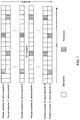
- FIG. 1 illustrates an example of a legacy downlink reference signal pattern. More specifically, the legacy downlink reference pattern is a cell-specific reference signal pattern utilized for coherent detection at a receiver, such as a mobile device.
- reference signals or pilot symbols
- Each subcarrier can include a slot, and the slot can include 17 symbols, which can consist of data symbols or pilot symbols in the time domain.
- the reference signals or pilot symbols
- a base station can assign one, two, or four subcarriers to send data signals to the mobile devices, thus allowing the mobile devices to estimate the channel based on the assignment.
- the previous solution of transmitting the reference signals (or pilot symbols) in every subcarrier may not be feasible with respect to CIoT devices.
- the redundancy of reference signals can degrade the throughput for the CIoT device.
- the commonality of the reference signals can make transmitting the reference signals in every subcarrier unduly burdensome.
- the legacy downlink reference pattern illustrated in FIG. 1 can present several drawbacks.
- the reference signal pattern can be designed based on the wireless channel characteristics between the base station and the mobile device.
- the pilot symbol pattern shown in FIG. 1 the number of reference signals (or pilot symbols) can be more than necessary for slow moving mobile devices.
- a PSAM channel estimator utilizes a two-dimensional Nyquist sampling theorem in OFDM systems, as given by:
- N t and N f are the allowed number of data samples between two reference signals (or two pilot symbols) in the time and frequency domains, respectively.
- f d,max is a maximum Doppler frequency
- L is the number of multipaths of wireless channels
- N is the number of available subcarriers in the OFDM symbol.
- pilot symbol patterns are independent of the mobile devices' channel characteristics and throughput.
- the wireless systems for CIoT devices are expected to service a large number of CIoT devices simultaneously.
- these wireless system architectures are to be appropriately designed to accommodate throughput conditions of the CIoT devices, e.g., short/sparse data transmissions.
- some classes of CIoT devices, especially coverage extended users may necessitate blind repetitions or spreading to be able to effectively reach the base station.
- Such classes of CIoT devices are expected to consume more resources as compared to other classes experiencing normal coverage (i.e.
- the wireless channels on assigned slots can be estimated from cell-specific reference signals either on the assigned resources or outside of the user's allocated resources, in the pilot symbol pattern in accordance with the present technology, the pilot symbol density can be reduced as compared to previous pilot symbol solutions by more sparsely transmitting reference signals on dispersed sub-carriers. As a result, improved spectral efficiency and flexibility can be achieved while maintaining a comparable error performance. The improved spectral efficiency can lead to a longer battery life for the mobile device.
- the present technology describes a pilot symbol pattern that can be utilized for downlink narrow band OFDMA with respect to CIoT devices.
- pilot symbol patterns can be used for different coverage classes.
- mobile devices in the same coverage class or associated with a same mobility level can each read the same pilot symbol pattern, which corresponds to the appropriate coverage class or mobility level.
- the reference signals (or pilot symbols) can be broadcasted to the mobile devices in accordance with a pattern that is constructed using TDM or FDM.
- FIG. 2 illustrates an exemplary pre-configured downlink reference signal pattern.
- the pattern of reference signals (or pilot symbols) can be received at a user equipment (UE) via a wireless channel, such as a cellular Internet of Things (CIoT) device, and the UE can utilize the reference signals to perform a channel estimation of the wireless channel.
- a base station can assign one, two of four subcarriers to send reference signals (or pilot symbols) to the UE for purposes of channel estimation.
- the reference signals (or pilot symbols) may not be inserted in every subcarrier. Rather, reference signals (or pilot symbols) can be inserted every N f subcarriers, and within a particular subcarrier, a reference signal (or pilot signal) can be inserted every N t symbols.
- N t and N f are the allowed number of data samples between two reference signals (or two pilot symbols) in the time and frequency domains, respectively.
- the subcarrier can include a slot, and the slot can include 17 symbols, which can consist of data symbols or pilot symbols in the time domain.
- the pilot symbol spacing parameters of N t and N f can be configured based on a number of usable subcarriers of an OFDM symbol, wireless channel characteristics, and an expected mobility of the UE.
- N t and N f are configurable parameters that can vary depending on the various factors described above.
- the 3 rd and 11 th symbols are reference signals (or pilot symbols) in subcarrier 0. Since there are 7 data symbols between the first pilot symbol (i.e., the 3 rd symbol) and the second pilot symbol (i.e., the 11 th symbol) in the time domain, in this example, N t is equal to 7.
- subcarrier 1 does not include any pilot symbols. Rather, the subsequent subcarrier with one or more pilot symbols is subcarrier N f ⁇ 1, wherein N f represents a pilot symbol spacing in the frequency domain.
- the 7 th and 15 th symbols are reference signals (or pilot symbols).
- a one two-dimensional channel estimation can be replaced by two one-dimensional channel estimators to reduce the computational complexity at the receiver (e.g., the CIoT device).
- the number of channel estimation processes to be utilized is the sum of the number of assigned subcarriers with pilot symbols in the frequency and time domains, respectively, e.g., 2 or 4, and N S , wherein N S is the number of OFDM symbols in a scheduling interval (as shown in FIG. 2 ).
- the number of channel estimation in the time domain can depend on the number of assigned subcarriers.
- the CIoT network is designed or configured for low device mobility, high device mobility, a small wireless channel delay spread, a large wireless channel delay spread, etc., sometimes such a design or configuration can result in a waste of resources for the reference signals (or pilot symbols) to estimate the wireless channel based on the Nyquist sampling theorem.
- a pilot symbol pattern with a spacing of 5 can be sufficient for performing channel estimation, but if a high mobility CIoT device only receives one pilot symbol for every 8 data symbols, then channel estimation at the high mobility CIoT device cannot be guaranteed.
- a pilot symbol pattern with a spacing of 8 can unnecessarily waste resources for low mobility CIoT devices.
- N i is a duration of a pilot pattern i at a base station.
- the duration can be one or more subframes, or a frame duration in narrow band (NB) OFDMA systems.
- NB-OFDMA narrow band
- the duration of a sub-frame and a frame are 160 milliseconds (ms) and 1.28 seconds (s), respectively.
- the set of common reference signals can be inserted in a cell-specific manner, and a cell specific shift in a frequency domain can function to avoid reference signal collisions (or pilot symbol collisions) from different cells.
- the transmitter e.g., the based station
- the transmitter can configure the set of reference signals in a static manner or dynamic manner.
- a density of reference signals (or pilot symbols) in the control channel can be higher than as compared to the data channel in order to maintain a suitable level of error performance.
- a dynamic pattern of reference signals can be determined by the coverage class of the CIoT devices, a mobility level of the CIoT devices and/or wireless channel characteristics.
- the dynamic pattern of reference signals can utilize time division multiplexing (TDM) or frequency division multiplexing (FDM).
- a duration of each pilot pattern (N i ) and a number of patterns (K) can be pre-determined or a configurable parameter.
- the duration of each pilot pattern (N i ) and the number of patterns (K) can be broadcasted via a broadcast channel.
- the duration of each pilot pattern (N i ) and the number of patterns (K) can be sent via higher layer signaling.
- a sparse pilot pattern can be a sub-sampled pattern of a dense pilot pattern.
- a nesting property or a subset of the dense pilot pattern can be utilized, thereby reducing the computational complexity at the receiver (e.g., the CIoT device).
- FDM patterns can be implemented in a manner similar to those in TDM.
- the base station can comprise one or more processors and memory configured to: identify, at the base station, a UE to receive a set of pre-configured downlink reference signals from the base station, wherein the set of pre-configured downlink reference signals include a set of pre-configured pilot symbols in accordance with a defined reference signal transmission pattern that is characterized by a first pilot symbol spacing parameter (N t ) in a subcarrier time domain and a second pilot symbol spacing parameter (N f ) in a subcarrier frequency domain, as in block 510 .
- N t first pilot symbol spacing parameter
- N f second pilot symbol spacing parameter
- the base station can comprise one or more processors and memory configured to: process, at the base station, the set of pre-configured downlink reference signals for transmission to the UE, wherein the set of pre-configured downlink reference signals are in accordance with the defined reference signal transmission pattern, wherein the UE is configured to detect the set of pre-configured downlink reference signals and perform a channel estimation based on the set of pre-configured downlink reference signals, as in block 520 .
- the CIoT device can comprise one or more processors and memory configured to: process, at the CIoT device, a set of pre-configured downlink reference signals received from a base station, wherein the set of pre-configured downlink reference signals include a set of pre-configured pilot symbols in accordance with a defined reference signal transmission pattern, wherein the defined reference signal transmission pattern is characterized by a first pilot symbol spacing parameter (N t ) in a subcarrier time domain and a second pilot symbol spacing parameter (N f ) in a subcarrier frequency domain, as in block 610 .
- the CIoT device can comprise one or more processors and memory configured to: perform, at the CIoT device, a channel estimation based on the set of pre-configured downlink reference signals received from the base station, as in block 620 .
- Another example provides at least one machine readable storage medium having instructions 700 embodied thereon for transmitting downlink reference signals from a base station to user equipments (UEs), as shown in the flow chart in FIG. 7 .
- the instructions can be executed on a machine, where the instructions are included on at least one computer readable medium or one non-transitory machine readable storage medium.
- the instructions when executed perform: identifying, using one or more processors at the base station, a UE to receive a set of pre-configured downlink reference signals from the base station, wherein the set of pre-configured downlink reference signals include a set of pre-configured pilot symbols in accordance with a defined reference signal transmission pattern that is characterized by a first pilot symbol spacing parameter (N t ) in a subcarrier time domain and a second pilot symbol spacing parameter (N f ) in a subcarrier frequency domain, as in block 710 .
- N t first pilot symbol spacing parameter
- N f second pilot symbol spacing parameter
- the instructions when executed perform: processing, using the one or more processors at the base station, the set of pre-configured downlink reference signals for transmission to the UE, wherein the set of pre-configured downlink reference signals are in accordance with the defined reference signal transmission pattern, wherein the UE is configured to detect the set of pre-configured downlink reference signals and perform a channel estimation based on the set of pre-configured downlink reference signals, as in block 720 .
- FIG. 8 provides an example illustration of a user equipment (UE) device 800 , such as a wireless device, a mobile station (MS), a mobile wireless device, a mobile communication device, a tablet, a handset, or other type of wireless device.
- the UE device 800 can include one or more antennas configured to communicate with a node 820 or transmission station, such as a base station (BS), an evolved Node B (eNB), a baseband unit (BBU), a remote radio head (RRH), a remote radio equipment (RRE), a relay station (RS), a radio equipment (RE), a remote radio unit (RRU), a central processing module (CPM), or other type of wireless wide area network (WWAN) access point.
- BS base station
- eNB evolved Node B
- BBU baseband unit
- RRH remote radio head
- RRE remote radio equipment
- RS relay station
- RE radio equipment
- RRU remote radio unit
- CCM central processing module
- the node 820 can include one or more processors 822 and memory 824 .
- the UE device 800 can be configured to communicate using at least one wireless communication standard including 3GPP LTE, WiMAX, High Speed Packet Access (HSPA), Bluetooth, and WiFi.
- the UE device 800 can communicate using separate antennas for each wireless communication standard or shared antennas for multiple wireless communication standards.
- the UE device 800 can communicate in a wireless local area network (WLAN), a wireless personal area network (WPAN), and/or a WWAN.
- WLAN wireless local area network
- WPAN wireless personal area network
- WWAN wireless wide area network
- the UE device 800 may include application circuitry 802 , baseband circuitry 804 , Radio Frequency (RF) circuitry 806 , front-end module (FEM) circuitry 808 and one or more antennas 810 , coupled together at least as shown.
- RF Radio Frequency
- FEM front-end module
- the application circuitry 802 may include one or more application processors.
- the application circuitry 802 may include circuitry such as, but not limited to, one or more single-core or multi-core processors.
- the processor(s) may include any combination of general-purpose processors and dedicated processors (e.g., graphics processors, application processors, etc.).
- the processors may be coupled with and/or may include a storage medium, and may be configured to execute instructions stored in the storage medium to enable various applications and/or operating systems to run on the system.
- the baseband circuitry 804 may include circuitry such as, but not limited to, one or more single-core or multi-core processors.
- the baseband circuitry 804 may include one or more baseband processors and/or control logic to process baseband signals received from a receive signal path of the RF circuitry 806 and to generate baseband signals for a transmit signal path of the RF circuitry 806 .
- Baseband processing circuitry 804 may interface with the application circuitry 802 for generation and processing of the baseband signals and for controlling operations of the RF circuitry 806 .
- the radio control functions may include, but are not limited to, signal modulation/demodulation, encoding/decoding, radio frequency shifting, etc.
- modulation/demodulation circuitry of the baseband circuitry 804 may include Fast-Fourier Transform (FFT), precoding, and/or constellation mapping/demapping functionality.
- encoding/decoding circuitry of the baseband circuitry 804 may include convolution, tail-biting convolution, turbo, Viterbi, and/or Low Density Parity Check (LDPC) encoder/decoder functionality.
- FFT Fast-Fourier Transform
- encoding/decoding circuitry of the baseband circuitry 804 may include convolution, tail-biting convolution, turbo, Viterbi, and/or Low Density Parity Check (LDPC) encoder/decoder functionality.
- LDPC Low Density Parity Check
- the baseband circuitry 804 may include elements of a protocol stack such as, for example, elements of an evolved universal terrestrial radio access network (EUTRAN) protocol including, for example, physical (PHY), media access control (MAC), radio link control (RLC), packet data convergence protocol (PDCP), and/or radio resource control (RRC) elements.
- EUTRAN evolved universal terrestrial radio access network
- a central processing unit (CPU) 804 e of the baseband circuitry 804 may be configured to run elements of the protocol stack for signaling of the PHY, MAC, RLC, PDCP and/or RRC layers.
- the baseband circuitry may include one or more audio digital signal processor(s) (DSP) 804 f .
- DSP audio digital signal processor
- the audio DSP(s) 804 f may be include elements for compression/decompression and echo cancellation and may include other suitable processing elements in other embodiments.
- Components of the baseband circuitry may be suitably combined in a single chip, a single chipset, or disposed on a same circuit board in some embodiments.
- some or all of the constituent components of the baseband circuitry 804 and the application circuitry 802 may be implemented together such as, for example, on a system on a chip (SOC).
- SOC system on a chip
- the baseband circuitry 804 may provide for communication compatible with one or more radio technologies.
- the baseband circuitry 804 may support communication with an evolved universal terrestrial radio access network (EUTRAN) and/or other wireless metropolitan area networks (WMAN), a wireless local area network (WLAN), a wireless personal area network (WPAN).
- EUTRAN evolved universal terrestrial radio access network
- WMAN wireless metropolitan area networks
- WLAN wireless local area network
- WPAN wireless personal area network
- multi-mode baseband circuitry Embodiments in which the baseband circuitry 804 is configured to support radio communications of more than one wireless protocol.
- the RF circuitry 806 may enable communication with wireless networks using modulated electromagnetic radiation through a non-solid medium.
- the RF circuitry 806 may include switches, filters, amplifiers, etc. to facilitate the communication with the wireless network.
- RF circuitry 806 may include a receive signal path which may include circuitry to down-convert RF signals received from the FEM circuitry 808 and provide baseband signals to the baseband circuitry 804 .
- RF circuitry 806 may also include a transmit signal path which may include circuitry to up-convert baseband signals provided by the baseband circuitry 804 and provide RF output signals to the FEM circuitry 808 for transmission.
- the RF circuitry 806 may include a receive signal path and a transmit signal path.
- the receive signal path of the RF circuitry 806 may include mixer circuitry 806 a , amplifier circuitry 806 b and filter circuitry 806 c .
- the transmit signal path of the RF circuitry 806 may include filter circuitry 806 c and mixer circuitry 806 a .
- RF circuitry 806 may also include synthesizer circuitry 806 d for synthesizing a frequency for use by the mixer circuitry 806 a of the receive signal path and the transmit signal path.
- a separate radio IC circuitry may be provided for processing signals for each spectrum, although the scope of the embodiments is not limited in this respect.
- the synthesizer circuitry 806 d may be a fractional-N synthesizer or a fractional N/N+1 synthesizer, although the scope of the embodiments is not limited in this respect as other types of frequency synthesizers may be suitable.
- synthesizer circuitry 806 d may be a delta-sigma synthesizer, a frequency multiplier, or a synthesizer comprising a phase-locked loop with a frequency divider.
- the synthesizer circuitry 806 d may be configured to synthesize an output frequency for use by the mixer circuitry 806 a of the RF circuitry 806 based on a frequency input and a divider control input. In some embodiments, the synthesizer circuitry 806 d may be a fractional N/N+1 synthesizer.
- FEM circuitry 808 may include a receive signal path which may include circuitry configured to operate on RF signals received from one or more antennas 810 , amplify the received signals and provide the amplified versions of the received signals to the RF circuitry 806 for further processing.
- FEM circuitry 808 may also include a transmit signal path which may include circuitry configured to amplify signals for transmission provided by the RF circuitry 806 for transmission by one or more of the one or more antennas 810 .
- the transmit signal path of the FEM circuitry 808 may include a power amplifier (PA) to amplify input RF signals (e.g., provided by RF circuitry 806 ), and one or more filters to generate RF signals for subsequent transmission (e.g., by one or more of the one or more antennas 810 .
- PA power amplifier
- FIG. 9 also provides an illustration of a microphone and one or more speakers that can be used for audio input and output from the wireless device.
- the display screen can be a liquid crystal display (LCD) screen, or other type of display screen such as an organic light emitting diode (OLED) display.
- the display screen can be configured as a touch screen.
- the touch screen can use capacitive, resistive, or another type of touch screen technology.
- An application processor and a graphics processor can be coupled to internal memory to provide processing and display capabilities.
- a non-volatile memory port can also be used to provide data input/output options to a user.
- the non-volatile memory port can also be used to expand the memory capabilities of the wireless device.
- a keyboard can be integrated with the wireless device or wirelessly connected to the wireless device to provide additional user input.
- a virtual keyboard can also be provided using the touch screen.
- Example 5 includes the apparatus of any of Examples 1-4, wherein the defined reference signal transmission pattern is a dynamic reference signal transmission pattern that utilizes time division multiplexing (TDM) or frequency division multiplexing (FDM).
- TDM time division multiplexing
- FDM frequency division multiplexing
- Example 11 includes the apparatus of any of Examples 1-10, further comprising: an application processor configured to identify the UE to receive the set of pre-configured downlink reference signals from the base station; and a baseband processor configured to process the set of pre-configured downlink reference signals for transmission to the UE.
- Modules may also be implemented in software for execution by various types of processors.
- An identified module of executable code may, for instance, comprise one or more physical or logical blocks of computer instructions, which may, for instance, be organized as an object, procedure, or function. Nevertheless, the executables of an identified module may not be physically located together, but may comprise disparate instructions stored in different locations which, when joined logically together, comprise the module and achieve the stated purpose for the module.
- a module of executable code may be a single instruction, or many instructions, and may even be distributed over several different code segments, among different programs, and across several memory devices.
- operational data may be identified and illustrated herein within modules, and may be embodied in any suitable form and organized within any suitable type of data structure. The operational data may be collected as a single data set, or may be distributed over different locations including over different storage devices, and may exist, at least partially, merely as electronic signals on a system or network.
- the modules may be passive or active, including agents operable to perform desired functions.
Abstract
Description
wherein L is a number of multipaths of wireless channels, τk is a delay of the kth path, and ck(t) is a corresponding complex amplitude. The magnitude, ck(t), ∀ k can be modeled as an independent, wide-sense stationary, narrowband complex Gaussian process with an average power of σk 2. Equivalently, the frequency response of the wireless channel at time t can be expressed as:
r H(n,k)=r t(n)·r f(k)
wherein:
and wherein Ts=(N+L)T is an OFDM symbol duration including a cyclic prefix, N is a number of available subcarriers in the OFDM symbol, fd,max is a maximum Doppler frequency, J0(⋅) is a zeroth-order Bessel function of a first kind, and Δf is a subcarrier spacing. Here, rt(n) is a correlation at the time domain, and rf(k) is a correlation at the frequency domain and is a function of a channel delay profile. As indicated, the coherence time and coherence bandwidth of the wireless channel are functions of the maximum Doppler frequency and the channel delay profile, respectively.
wherein Nt and Nf are the allowed number of data samples between two reference signals (or two pilot symbols) in the time and frequency domains, respectively. In addition, fd,max is a maximum Doppler frequency, Ts=(N+L)T is the OFDM symbol duration including the cyclic prefix, L is the number of multipaths of wireless channels, and N is the number of available subcarriers in the OFDM symbol. Based on the 2D Nyquist sampling theorem, the number of data symbols allowed between the pilot symbols is based on the Nyquist sampling theorem, which is given by the equations above. Hence, Nt can refer to a time domain separation between the reference signals (or pilot symbols), and Nf can refer to the frequency domain separation between the reference signals (or pilot symbols).
Claims (15)
Priority Applications (1)
| Application Number | Priority Date | Filing Date | Title |
|---|---|---|---|
| US15/746,776 US10931422B2 (en) | 2015-07-27 | 2015-12-24 | Transmitting downlink reference signals to user equipments (UEs) |
Applications Claiming Priority (3)
| Application Number | Priority Date | Filing Date | Title |
|---|---|---|---|
| US201562197332P | 2015-07-27 | 2015-07-27 | |
| PCT/US2015/000354 WO2017018969A1 (en) | 2015-07-27 | 2015-12-24 | Downlink reference signal patterns |
| US15/746,776 US10931422B2 (en) | 2015-07-27 | 2015-12-24 | Transmitting downlink reference signals to user equipments (UEs) |
Publications (2)
| Publication Number | Publication Date |
|---|---|
| US20180219662A1 US20180219662A1 (en) | 2018-08-02 |
| US10931422B2 true US10931422B2 (en) | 2021-02-23 |
Family
ID=55237894
Family Applications (1)
| Application Number | Title | Priority Date | Filing Date |
|---|---|---|---|
| US15/746,776 Active 2035-12-28 US10931422B2 (en) | 2015-07-27 | 2015-12-24 | Transmitting downlink reference signals to user equipments (UEs) |
Country Status (5)
| Country | Link |
|---|---|
| US (1) | US10931422B2 (en) |
| EP (1) | EP3329625A1 (en) |
| CN (1) | CN107820686B (en) |
| HK (1) | HK1251975A1 (en) |
| WO (1) | WO2017018969A1 (en) |
Families Citing this family (10)
| Publication number | Priority date | Publication date | Assignee | Title |
|---|---|---|---|---|
| CN108432318B (en) * | 2016-01-08 | 2021-01-01 | 华为技术有限公司 | Information sending method, device and system |
| WO2018014191A1 (en) * | 2016-07-19 | 2018-01-25 | Nec Corporation | Method and device for performing communication |
| CN109923909B (en) * | 2016-11-04 | 2021-12-17 | 瑞典爱立信有限公司 | Wireless device and network node for wireless communication system and method thereof |
| JP7242161B2 (en) * | 2017-06-14 | 2023-03-20 | ソニーグループ株式会社 | COMMUNICATION DEVICE, COMMUNICATION CONTROL METHOD AND COMPUTER PROGRAM |
| US20220022053A1 (en) * | 2018-12-06 | 2022-01-20 | Ntt Docomo, Inc. | User terminal |
| US20220103293A1 (en) * | 2019-02-15 | 2022-03-31 | Nokia Technologies Oy | Optimized multi connectivity and data duplication |
| US11258565B2 (en) | 2019-08-30 | 2022-02-22 | Huawei Technologies Co., Ltd. | Sparse reference signal-related signaling apparatus and methods |
| US11569961B2 (en) | 2019-08-30 | 2023-01-31 | Huawei Technologies Co., Ltd. | Reference signaling overhead reduction apparatus and methods |
| CN114600396B (en) * | 2019-11-20 | 2024-01-09 | 谷歌有限责任公司 | Method and apparatus for mitigating co-channel interference |
| CN111955035B (en) * | 2020-06-05 | 2022-11-22 | 北京小米移动软件有限公司 | Transmission method and device of positioning reference signal, electronic equipment and storage medium |
Citations (10)
| Publication number | Priority date | Publication date | Assignee | Title |
|---|---|---|---|---|
| CN101272372A (en) | 2008-03-31 | 2008-09-24 | 北京北方烽火科技有限公司 | OFDM automatic closed-loop transmitting scattered pilot insertion control method |
| CN101674119A (en) | 2008-09-09 | 2010-03-17 | 富士通株式会社 | Multi-input multi-output-orthogonal frequency division multiplexing sending and receiving equipment and method |
| US20120207126A1 (en) | 2011-02-14 | 2012-08-16 | Futurewei Technologies, Inc. | Control Channel Transmission and Reception Method and System |
| CN102917371A (en) | 2012-10-25 | 2013-02-06 | 北京大学 | Special reference signal optimization method suitable for LTE (long-term evolution) cell of indoor channel |
| CN103124210A (en) | 2011-03-25 | 2013-05-29 | 北京新岸线移动多媒体技术有限公司 | Method and device for configuring pilot frequency of wireless communication system |
| US20140044054A1 (en) * | 2012-08-08 | 2014-02-13 | Joon Beom Kim | Method and system having reference signal design for new carrier types |
| WO2014088185A1 (en) | 2012-12-04 | 2014-06-12 | Lg Electronics Inc. | Method for changing pattern of reference signals according to coherence time variation in wireless communication system and apparatus therefor |
| US20180270803A1 (en) * | 2015-09-25 | 2018-09-20 | Lg Electronics Inc. | Method for transmitting uplink data in wireless communication system and apparatus for method |
| US20180270008A1 (en) * | 2015-09-02 | 2018-09-20 | Lg Electronics Inc. | Method and apparatus for performing cell search in wireless communication system |
| US20190044690A1 (en) * | 2015-09-24 | 2019-02-07 | Lg Electronics Inc. | Method and apparatus for handling various iot network access in wireless communication system |
-
2015
- 2015-12-24 CN CN201580081228.0A patent/CN107820686B/en active Active
- 2015-12-24 US US15/746,776 patent/US10931422B2/en active Active
- 2015-12-24 WO PCT/US2015/000354 patent/WO2017018969A1/en active Application Filing
- 2015-12-24 EP EP15828792.0A patent/EP3329625A1/en active Pending
-
2018
- 2018-09-04 HK HK18111293.1A patent/HK1251975A1/en unknown
Patent Citations (10)
| Publication number | Priority date | Publication date | Assignee | Title |
|---|---|---|---|---|
| CN101272372A (en) | 2008-03-31 | 2008-09-24 | 北京北方烽火科技有限公司 | OFDM automatic closed-loop transmitting scattered pilot insertion control method |
| CN101674119A (en) | 2008-09-09 | 2010-03-17 | 富士通株式会社 | Multi-input multi-output-orthogonal frequency division multiplexing sending and receiving equipment and method |
| US20120207126A1 (en) | 2011-02-14 | 2012-08-16 | Futurewei Technologies, Inc. | Control Channel Transmission and Reception Method and System |
| CN103124210A (en) | 2011-03-25 | 2013-05-29 | 北京新岸线移动多媒体技术有限公司 | Method and device for configuring pilot frequency of wireless communication system |
| US20140044054A1 (en) * | 2012-08-08 | 2014-02-13 | Joon Beom Kim | Method and system having reference signal design for new carrier types |
| CN102917371A (en) | 2012-10-25 | 2013-02-06 | 北京大学 | Special reference signal optimization method suitable for LTE (long-term evolution) cell of indoor channel |
| WO2014088185A1 (en) | 2012-12-04 | 2014-06-12 | Lg Electronics Inc. | Method for changing pattern of reference signals according to coherence time variation in wireless communication system and apparatus therefor |
| US20180270008A1 (en) * | 2015-09-02 | 2018-09-20 | Lg Electronics Inc. | Method and apparatus for performing cell search in wireless communication system |
| US20190044690A1 (en) * | 2015-09-24 | 2019-02-07 | Lg Electronics Inc. | Method and apparatus for handling various iot network access in wireless communication system |
| US20180270803A1 (en) * | 2015-09-25 | 2018-09-20 | Lg Electronics Inc. | Method for transmitting uplink data in wireless communication system and apparatus for method |
Non-Patent Citations (10)
| Title |
|---|
| 3GPP TR 45.820; "3rd Generation Partnership Project; Technical Specification Group GSM/EDGE Radio Access Network; Cellular System Support for Ultra Low complexity and Low Throughput Internet of Things"; (May 2015); 162 pages; V1.2.1 (Release 13). |
| EPO; Office Action issued in EP Patent Application No. 15828792.0, dated Jun. 5, 2020; 9 pages. |
| Intel Corporation; "EC-GSM-Link-Level Performance of EC-PCH"; 3GPP TSG GP-150407; (May 25-29, 2015); 7 pages; GERAN Meeting #66, Vilnius, Lithuania; Agenda 7.1.5.3.5. |
| Intel Corporation; "EC-GSM—Link-Level Performance of EC-PCH"; 3GPP TSG GP-150407; (May 25-29, 2015); 7 pages; GERAN Meeting #66, Vilnius, Lithuania; Agenda 7.1.5.3.5. |
| International Preliminary Report on Patentability dated Jan. 30, 2018, in International Application No. PCT/US2015/000354, filed Dec. 24, 2015; 7 pages. |
| QUALCOMM Incorporated, et al.; "NB-CIOT-Downlink Physical Layer Design," SGPP TSG GERAN; Jun. 24, 2015; 13 pages. |
| QUALCOMM Incorporated, et al.; "NB-CIOT—Downlink Physical Layer Design," SGPP TSG GERAN; Jun. 24, 2015; 13 pages. |
| SIPO; First Office Action issued in CN Patent Application No. 201580081228.0, dated May 12, 2020; 18 pages including English translation available. |
| Vodafone Group PLC.; "New Study Item on Cellular System Support for Ultra Low Complexity and Low Throughput Internet of Things"; 3GPP TSG GP-140421; (May 26-30, 2014); 6 pages; GERAN Meeting #62, Valencia, Spain; rev of GP-140418 rev of GP-140411; Agenda 11.1. |
| Ye et al.; "Pilot-Symbol-Aided Channel Estimation for OFDM in Wireless Systems"; IEEE Transactions on Vehicular Technology; (Jul. 2000); pp. 1207-1215; vol. 49, No. 4. |
Also Published As
| Publication number | Publication date |
|---|---|
| US20180219662A1 (en) | 2018-08-02 |
| CN107820686B (en) | 2021-11-02 |
| HK1251975A1 (en) | 2019-05-10 |
| EP3329625A1 (en) | 2018-06-06 |
| WO2017018969A1 (en) | 2017-02-02 |
| CN107820686A (en) | 2018-03-20 |
Similar Documents
| Publication | Publication Date | Title |
|---|---|---|
| US10931422B2 (en) | Transmitting downlink reference signals to user equipments (UEs) | |
| US11723002B2 (en) | Short transmission time interval (TTI) | |
| CN107852264B (en) | Beamformed Physical Downlink Control Channel (BPDCCH) for narrow beam based wireless communication | |
| US10491334B2 (en) | Flexible universal extended frame structure | |
| US10849001B2 (en) | Measurement restrictions for CoMP | |
| US10154486B2 (en) | Downlink signaling for UE specific cyclic prefix transmission | |
| US11622377B2 (en) | Scheduling request for standalone deployment of a system using beamforming | |
| US20200260527A1 (en) | Enhanced self-contained time-division duplex subframe structure | |
| EP3403350B1 (en) | Acknowledgement (ack) transmissions using a self-contained subframe structure | |
| US10849082B2 (en) | Configuration of measurement subframes for a user equipment (UE) | |
| US11050504B2 (en) | Enhanced overlaid code division multiple access (CDMA) | |
| WO2018031583A1 (en) | Method of heterogeneous brs transmission in nr | |
| WO2017099836A1 (en) | Beam refinement reference signal generation |
Legal Events
| Date | Code | Title | Description |
|---|---|---|---|
| FEPP | Fee payment procedure |
Free format text: ENTITY STATUS SET TO UNDISCOUNTED (ORIGINAL EVENT CODE: BIG.); ENTITY STATUS OF PATENT OWNER: LARGE ENTITY |
|
| AS | Assignment |
Owner name: INTEL CORPORATION, CALIFORNIA Free format text: ASSIGNMENT OF ASSIGNORS INTEREST;ASSIGNORS:KIM, JOONBEOM;SIVANESAN, KATHIRAVETPILLAI;BANJADE, VESH RAJ SHARMA;AND OTHERS;SIGNING DATES FROM 20171025 TO 20171030;REEL/FRAME:044774/0418 |
|
| STPP | Information on status: patent application and granting procedure in general |
Free format text: DOCKETED NEW CASE - READY FOR EXAMINATION |
|
| STPP | Information on status: patent application and granting procedure in general |
Free format text: NON FINAL ACTION MAILED |
|
| STPP | Information on status: patent application and granting procedure in general |
Free format text: RESPONSE TO NON-FINAL OFFICE ACTION ENTERED AND FORWARDED TO EXAMINER |
|
| STPP | Information on status: patent application and granting procedure in general |
Free format text: FINAL REJECTION MAILED |
|
| STPP | Information on status: patent application and granting procedure in general |
Free format text: RESPONSE AFTER FINAL ACTION FORWARDED TO EXAMINER |
|
| STPP | Information on status: patent application and granting procedure in general |
Free format text: NON FINAL ACTION MAILED |
|
| STCF | Information on status: patent grant |
Free format text: PATENTED CASE |
|
| MAFP | Maintenance fee payment |
Free format text: PAYMENT OF MAINTENANCE FEE, 4TH YEAR, LARGE ENTITY (ORIGINAL EVENT CODE: M1551); ENTITY STATUS OF PATENT OWNER: LARGE ENTITY Year of fee payment: 4 |