US10514130B2 - Tube array type nitrogen canister - Google Patents
Tube array type nitrogen canister Download PDFInfo
- Publication number
- US10514130B2 US10514130B2 US15/811,161 US201715811161A US10514130B2 US 10514130 B2 US10514130 B2 US 10514130B2 US 201715811161 A US201715811161 A US 201715811161A US 10514130 B2 US10514130 B2 US 10514130B2
- Authority
- US
- United States
- Prior art keywords
- tube
- top cap
- array
- liquid nitrogen
- type liquid
- Prior art date
- Legal status (The legal status is an assumption and is not a legal conclusion. Google has not performed a legal analysis and makes no representation as to the accuracy of the status listed.)
- Active, expires
Links
Images


Classifications
-
- B—PERFORMING OPERATIONS; TRANSPORTING
- B65—CONVEYING; PACKING; STORING; HANDLING THIN OR FILAMENTARY MATERIAL
- B65D—CONTAINERS FOR STORAGE OR TRANSPORT OF ARTICLES OR MATERIALS, e.g. BAGS, BARRELS, BOTTLES, BOXES, CANS, CARTONS, CRATES, DRUMS, JARS, TANKS, HOPPERS, FORWARDING CONTAINERS; ACCESSORIES, CLOSURES, OR FITTINGS THEREFOR; PACKAGING ELEMENTS; PACKAGES
- B65D81/00—Containers, packaging elements, or packages, for contents presenting particular transport or storage problems, or adapted to be used for non-packaging purposes after removal of contents
- B65D81/38—Containers, packaging elements, or packages, for contents presenting particular transport or storage problems, or adapted to be used for non-packaging purposes after removal of contents with thermal insulation
- B65D81/3837—Containers, packaging elements, or packages, for contents presenting particular transport or storage problems, or adapted to be used for non-packaging purposes after removal of contents with thermal insulation rigid container in the form of a bottle, jar or like container
- B65D81/3841—Containers, packaging elements, or packages, for contents presenting particular transport or storage problems, or adapted to be used for non-packaging purposes after removal of contents with thermal insulation rigid container in the form of a bottle, jar or like container formed with double walls, i.e. hollow
-
- F—MECHANICAL ENGINEERING; LIGHTING; HEATING; WEAPONS; BLASTING
- F17—STORING OR DISTRIBUTING GASES OR LIQUIDS
- F17C—VESSELS FOR CONTAINING OR STORING COMPRESSED, LIQUEFIED OR SOLIDIFIED GASES; FIXED-CAPACITY GAS-HOLDERS; FILLING VESSELS WITH, OR DISCHARGING FROM VESSELS, COMPRESSED, LIQUEFIED, OR SOLIDIFIED GASES
- F17C13/00—Details of vessels or of the filling or discharging of vessels
- F17C13/001—Thermal insulation specially adapted for cryogenic vessels
-
- A—HUMAN NECESSITIES
- A01—AGRICULTURE; FORESTRY; ANIMAL HUSBANDRY; HUNTING; TRAPPING; FISHING
- A01N—PRESERVATION OF BODIES OF HUMANS OR ANIMALS OR PLANTS OR PARTS THEREOF; BIOCIDES, e.g. AS DISINFECTANTS, AS PESTICIDES OR AS HERBICIDES; PEST REPELLANTS OR ATTRACTANTS; PLANT GROWTH REGULATORS
- A01N1/00—Preservation of bodies of humans or animals, or parts thereof
- A01N1/02—Preservation of living parts
- A01N1/0236—Mechanical aspects
- A01N1/0242—Apparatuses, i.e. devices used in the process of preservation of living parts, such as pumps, refrigeration devices or any other devices featuring moving parts and/or temperature controlling components
- A01N1/0252—Temperature controlling refrigerating apparatus, i.e. devices used to actively control the temperature of a designated internal volume, e.g. refrigerators, freeze-drying apparatus or liquid nitrogen baths
- A01N1/0257—Stationary or portable vessels generating cryogenic temperatures
-
- B—PERFORMING OPERATIONS; TRANSPORTING
- B65—CONVEYING; PACKING; STORING; HANDLING THIN OR FILAMENTARY MATERIAL
- B65D—CONTAINERS FOR STORAGE OR TRANSPORT OF ARTICLES OR MATERIALS, e.g. BAGS, BARRELS, BOTTLES, BOXES, CANS, CARTONS, CRATES, DRUMS, JARS, TANKS, HOPPERS, FORWARDING CONTAINERS; ACCESSORIES, CLOSURES, OR FITTINGS THEREFOR; PACKAGING ELEMENTS; PACKAGES
- B65D25/00—Details of other kinds or types of rigid or semi-rigid containers
-
- B—PERFORMING OPERATIONS; TRANSPORTING
- B65—CONVEYING; PACKING; STORING; HANDLING THIN OR FILAMENTARY MATERIAL
- B65D—CONTAINERS FOR STORAGE OR TRANSPORT OF ARTICLES OR MATERIALS, e.g. BAGS, BARRELS, BOTTLES, BOXES, CANS, CARTONS, CRATES, DRUMS, JARS, TANKS, HOPPERS, FORWARDING CONTAINERS; ACCESSORIES, CLOSURES, OR FITTINGS THEREFOR; PACKAGING ELEMENTS; PACKAGES
- B65D81/00—Containers, packaging elements, or packages, for contents presenting particular transport or storage problems, or adapted to be used for non-packaging purposes after removal of contents
- B65D81/18—Containers, packaging elements, or packages, for contents presenting particular transport or storage problems, or adapted to be used for non-packaging purposes after removal of contents providing specific environment for contents, e.g. temperature above or below ambient
-
- F—MECHANICAL ENGINEERING; LIGHTING; HEATING; WEAPONS; BLASTING
- F17—STORING OR DISTRIBUTING GASES OR LIQUIDS
- F17C—VESSELS FOR CONTAINING OR STORING COMPRESSED, LIQUEFIED OR SOLIDIFIED GASES; FIXED-CAPACITY GAS-HOLDERS; FILLING VESSELS WITH, OR DISCHARGING FROM VESSELS, COMPRESSED, LIQUEFIED, OR SOLIDIFIED GASES
- F17C13/00—Details of vessels or of the filling or discharging of vessels
- F17C13/02—Special adaptations of indicating, measuring, or monitoring equipment
-
- F—MECHANICAL ENGINEERING; LIGHTING; HEATING; WEAPONS; BLASTING
- F17—STORING OR DISTRIBUTING GASES OR LIQUIDS
- F17C—VESSELS FOR CONTAINING OR STORING COMPRESSED, LIQUEFIED OR SOLIDIFIED GASES; FIXED-CAPACITY GAS-HOLDERS; FILLING VESSELS WITH, OR DISCHARGING FROM VESSELS, COMPRESSED, LIQUEFIED, OR SOLIDIFIED GASES
- F17C13/00—Details of vessels or of the filling or discharging of vessels
- F17C13/06—Closures, e.g. cap, breakable member
-
- F—MECHANICAL ENGINEERING; LIGHTING; HEATING; WEAPONS; BLASTING
- F17—STORING OR DISTRIBUTING GASES OR LIQUIDS
- F17C—VESSELS FOR CONTAINING OR STORING COMPRESSED, LIQUEFIED OR SOLIDIFIED GASES; FIXED-CAPACITY GAS-HOLDERS; FILLING VESSELS WITH, OR DISCHARGING FROM VESSELS, COMPRESSED, LIQUEFIED, OR SOLIDIFIED GASES
- F17C7/00—Methods or apparatus for discharging liquefied, solidified, or compressed gases from pressure vessels, not covered by another subclass
- F17C7/02—Discharging liquefied gases
-
- F—MECHANICAL ENGINEERING; LIGHTING; HEATING; WEAPONS; BLASTING
- F17—STORING OR DISTRIBUTING GASES OR LIQUIDS
- F17C—VESSELS FOR CONTAINING OR STORING COMPRESSED, LIQUEFIED OR SOLIDIFIED GASES; FIXED-CAPACITY GAS-HOLDERS; FILLING VESSELS WITH, OR DISCHARGING FROM VESSELS, COMPRESSED, LIQUEFIED, OR SOLIDIFIED GASES
- F17C2201/00—Vessel construction, in particular geometry, arrangement or size
- F17C2201/01—Shape
- F17C2201/0104—Shape cylindrical
- F17C2201/0119—Shape cylindrical with flat end-piece
-
- F—MECHANICAL ENGINEERING; LIGHTING; HEATING; WEAPONS; BLASTING
- F17—STORING OR DISTRIBUTING GASES OR LIQUIDS
- F17C—VESSELS FOR CONTAINING OR STORING COMPRESSED, LIQUEFIED OR SOLIDIFIED GASES; FIXED-CAPACITY GAS-HOLDERS; FILLING VESSELS WITH, OR DISCHARGING FROM VESSELS, COMPRESSED, LIQUEFIED, OR SOLIDIFIED GASES
- F17C2203/00—Vessel construction, in particular walls or details thereof
- F17C2203/03—Thermal insulations
- F17C2203/0391—Thermal insulations by vacuum
-
- F—MECHANICAL ENGINEERING; LIGHTING; HEATING; WEAPONS; BLASTING
- F17—STORING OR DISTRIBUTING GASES OR LIQUIDS
- F17C—VESSELS FOR CONTAINING OR STORING COMPRESSED, LIQUEFIED OR SOLIDIFIED GASES; FIXED-CAPACITY GAS-HOLDERS; FILLING VESSELS WITH, OR DISCHARGING FROM VESSELS, COMPRESSED, LIQUEFIED, OR SOLIDIFIED GASES
- F17C2205/00—Vessel construction, in particular mounting arrangements, attachments or identifications means
- F17C2205/03—Fluid connections, filters, valves, closure means or other attachments
- F17C2205/0302—Fittings, valves, filters, or components in connection with the gas storage device
- F17C2205/0352—Pipes
- F17C2205/0361—Pipes corrugated
-
- F—MECHANICAL ENGINEERING; LIGHTING; HEATING; WEAPONS; BLASTING
- F17—STORING OR DISTRIBUTING GASES OR LIQUIDS
- F17C—VESSELS FOR CONTAINING OR STORING COMPRESSED, LIQUEFIED OR SOLIDIFIED GASES; FIXED-CAPACITY GAS-HOLDERS; FILLING VESSELS WITH, OR DISCHARGING FROM VESSELS, COMPRESSED, LIQUEFIED, OR SOLIDIFIED GASES
- F17C2221/00—Handled fluid, in particular type of fluid
- F17C2221/01—Pure fluids
- F17C2221/014—Nitrogen
-
- F—MECHANICAL ENGINEERING; LIGHTING; HEATING; WEAPONS; BLASTING
- F17—STORING OR DISTRIBUTING GASES OR LIQUIDS
- F17C—VESSELS FOR CONTAINING OR STORING COMPRESSED, LIQUEFIED OR SOLIDIFIED GASES; FIXED-CAPACITY GAS-HOLDERS; FILLING VESSELS WITH, OR DISCHARGING FROM VESSELS, COMPRESSED, LIQUEFIED, OR SOLIDIFIED GASES
- F17C2250/00—Accessories; Control means; Indicating, measuring or monitoring of parameters
- F17C2250/04—Indicating or measuring of parameters as input values
- F17C2250/0404—Parameters indicated or measured
- F17C2250/0478—Position or presence
-
- F—MECHANICAL ENGINEERING; LIGHTING; HEATING; WEAPONS; BLASTING
- F17—STORING OR DISTRIBUTING GASES OR LIQUIDS
- F17C—VESSELS FOR CONTAINING OR STORING COMPRESSED, LIQUEFIED OR SOLIDIFIED GASES; FIXED-CAPACITY GAS-HOLDERS; FILLING VESSELS WITH, OR DISCHARGING FROM VESSELS, COMPRESSED, LIQUEFIED, OR SOLIDIFIED GASES
- F17C2270/00—Applications
- F17C2270/05—Applications for industrial use
- F17C2270/0509—"Dewar" vessels
Definitions
- the present invention relates to a tube-array-type liquid nitrogen container.
- Liquid nitrogen containers are extensively used in hospitals and laboratories, mainly for freezing and storing biological materials such as cells and tissues.
- a traditional liquid nitrogen container typically is a double-layer vacuum container that is made by soldering.
- Such a container has eccentrically an opening and internally a rotatable inner rotator.
- the inner rotator carries a basket, in which freezing tubes are loaded. Since soldering of such a large device unavoidably has some deformation, accurate rotation of the inner rotator is hard to achieve, in turn making automatic storage of freezing tubes impossible.
- the present invention provides a tube-array-type liquid nitrogen container.
- a tube-array-type liquid nitrogen container comprises a container body that has a mouth; a tube array component that is received in the container body; and a top cap that seals the mouth from above.
- the top cap is rotatable in the mouth.
- the tube array component includes a plurality of holding tubes each configured to hold a freezing tube.
- the holding tube is opened at one end thereof, wherein the opening faces the top cap.
- the top cap has at least one tube access passing therethrough, and each tube access is atop covered by a tube access cover.
- the tube-array-type liquid nitrogen container uses a tube-array component composed of a plurality of holding tubes to store freezing tubes, and with the cooperation of the top cap and the external robotic arm, it realizes automatic access of freezing tubes.
- the container body has a double-layer structure with a vacuum zone sandwiched between its two layers. Since the intermediate space of the container body is applied with vacuum to form the vacuum zone that provides thermal insulation to the interior of the container body.
- the container body comprises an inner column and an outer column sleeved outside the inner column.
- the inner column and the outer column are fixed to each other at bottom.
- the inner column has its top lower than the top of the outer column.
- the inner column and the outer column have their tops connected through a corrugated pipe.
- the corrugated pipe has a wall thickness much smaller than the thickness of the inner column, and meanwhile the stroke is increased by more than one time, so as to reduce heat transmitted to the bottom of the inner column, thereby reducing loss of the liquid nitrogen.
- the container body further comprises a sleeve for the corrugated pipe.
- the sleeve for the corrugated pipe comprises a sleeve end fixed to the top of the outer column and a sleeve body extending downward from the sleeve end.
- the sleeve body is located inside the corrugated pipe.
- the sleeve body has its outer periphery that faces the corrugated pipe fitted with the inner periphery of the corrugated pipe, and the sleeve body has its lower end portion fixed to the inner column.
- the sleeve for the corrugated pipe prevents the inner column deformation caused by corrugated pipe being lengthened.
- the inner periphery of the sleeve body is axially sloped and is fitted with the top cap in a sealing manner.
- the sleeve body with the sloped inner periphery can fit with top cap in a sealing manner better.
- tube array component further comprises an upper positioning plate, a lower positioning plate, and a central axle that fixedly connects the upper positioning plate and the lower positioning plate.
- the upper positioning plate is provided with a plurality of upper positioning holes
- the lower positioning plate is provided with a plurality of lower positioning holes.
- Each of the upper positioning holes is coaxially aligned with one of the lower positioning holes.
- the holding tube passes through the upper positioning hole and gets positioned in the corresponding lower positioning hole.
- an auxiliary ball is arranged at the bottom of the holding tube, and the freezing tube is rested on the auxiliary ball.
- the auxiliary ball In addition to pushing the freezing tube during the tube-drawing operation, the auxiliary ball also provides damping function when the freezing tube moves downward in the holding tube.
- the top cap is provided with at least one position sensor.
- the position sensors may be arranged in circumferential direction of the top cap. The position sensors detect the rotation angle of the top cap, so as to ensure that the top cap rotates accurately.
- the tube access covers the entire area in radial direction of the tube array component. No matter where the access site of the freezing tube is in the tube array component, the tube access can be aligned to the tube access site by simply rotating the top cap for a certain angle.
- the tube access cover comprises a roof for the tube access cover and a insulating layer for the tube access cover, wherein the insulating layer is located below the roof, and the insulating layer is fitted with the tube access in a sealing manner.
- the insulating layer for the tube access cover and the tube access fitting with each other in a sealing manner good thermal insulation can be achieved at the tube access.
- the present invention provides the following positive advancements:
- the tube-array-type liquid nitrogen container uses a tube-array component composed of a plurality of holding tubes to store the freezing tubes, and is cooperated with the rotatable top cap and an external robotic arm, thereby improving space utilization and thermal insulation, effectively ensuring safety of the freezing tubes, and facilitating automatic storage of freezing tubes.
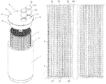
- FIG. 1 is an exploded view of a tube-array-type liquid nitrogen container of the present invention.
- FIG. 2 is a structural drawing of the container body of the tube-array-type liquid nitrogen container of FIG. 1 .
- FIG. 3 is a partial enlarged view of the container body of FIG. 2 .
- FIG. 4 is a structural schematic drawing of the tube-array component of the tube-array-type liquid nitrogen container of FIG. 1 .
- FIG. 5 is a partial enlarged view of the tube-array component of FIG. 4 .
- the present invention provides a tube-array-type liquid nitrogen container. It comprises a container body 1 that has a mouth 11 ; a tube array component 2 that is received in the container body 1 ; and a top cap 3 that seals the mouth 11 from above.
- the top cap 3 is rotatable in the mouth 11 .
- the tube array component 2 comprises a plurality of holding tubes 21 each configured to hold a freezing tube 4 .
- the holding tube 21 is opened at one end thereof, wherein the opening of the holding tube 21 faces the top cap 3 .
- the top cap 3 has at least one tube access 31 , which tube access passes through the top cap 3 . On the top, the tube access 31 is covered by a tube access cover 32 .
- the tube-array-type liquid nitrogen container is configured to work with an external robotic arm for automatic access of the freezing tubes through the following process.
- the external robotic arm rotates the top cap 3 first such that the tube access 31 of the top cap 3 is moved to a targeted site (i.e. a place above the holding tube 21 that holds the targeted freezing tube 4 ), and then lifts the tube access cover 32 to open the tube access 31 .
- the robotic arm activates and moves its tube-drawing head toward the tube array component 2 from above, so as to form an upward drawing force in the holding tube 21 that holds the targeted freezing tube 4 , and draw the freezing tube 4 from above until the freezing tube 4 enters the tube-drawing head.
- the external robotic arm To store a freezing tube, the external robotic arm first rotates the top cap 3 such that the tube access 31 of the top cap 3 is moved to a targeted site (i.e. a place above the holding tube 21 that is going to receive the freezing tube 4 ), and then lifts the tube access cover 32 to open the tube access 31 . At last, the robotic arm places the freezing tube 4 to be stored into the holding tube 21 .
- a targeted site i.e. a place above the holding tube 21 that is going to receive the freezing tube 4
- the robotic arm places the freezing tube 4 to be stored into the holding tube 21 .
- the tube-array-type liquid nitrogen container uses a tube-array component 2 composed of a plurality of holding tubes 21 to store freezing tubes 4 , and with the cooperation of the top cap 3 and the external robotic arm, it realizes automatic access of freezing tubes 4 .
- the container body 1 has a double-layer structure with a vacuum zone sandwiched between its two layers.
- the intermediate space of the container body 1 is applied with vacuum to form a vacuum zone, which provides thermal insulation to the interior of the container body 1 .
- the container body 1 has the following configuration.
- the container body 1 comprises an outer column 12 and an inner column 13 , which is enclosed by the outer column 12 at outside.
- the inner column 13 and the outer column 12 are fixed to each other at bottom.
- the inner column 13 has its top lower than the top of the outer column 12 .
- the inner column 13 and the outer column 12 have their tops connected through a corrugated pipe 14 .
- the corrugated pipe 14 has a wall thickness much smaller than the thickness of the inner column 13 , and meanwhile the pathway is increased by more than one time, so as to reduce heat transmitted to the bottom of the inner column 13 , thereby reducing loss of the liquid nitrogen.
- the vacuum zone applies a downward pressure to the inner column 13 .
- a sleeve 15 for the corrugated pipe precisely fitting the corrugation profile of the corrugated pipe 14 is sleeved on the corrugated pipe 14 .
- the sleeve 15 for the corrugated pipe is made of a non-metal material that has low thermal conductivity.
- the sleeve 15 for the corrugated pipe is configured as below.
- the sleeve 15 for the corrugated pipe comprises a sleeve end 151 fixed to the top of the outer column 12 and a sleeve body 152 extending downward from the sleeve end 151 .
- the sleeve body 152 is located inside the corrugated pipe 14 .
- the outer periphery of the sleeve body 152 that faces the corrugated pipe 14 is fitted with the inner periphery of the corrugated pipe 14 .
- the sleeve body 152 has its lower end portion fixed to the inner column 13 .
- the inner periphery of the sleeve body 152 is such axially sloped that the inner periphery of the sleeve body 152 and the top cap 3 are fitted with each other in a sealing manner.
- the top cap 3 comprises a top cap roof 33 and a top cap insulating layer 34 located below the top cap roof 33 .
- the inner periphery of the sleeve body 152 and the outer periphery of the top cap insulating layer 34 are fitted with each other in a sealing manner.
- the tube array component 2 further comprises an upper positioning plate 22 , a lower positioning plate 23 , and a central axle 24 that fastens the upper positioning plate 22 and the lower positioning plate 23 .
- the upper positioning plate 22 is provided with a plurality of upper positioning holes
- the lower positioning plate 23 is provided with a plurality of lower positioning holes.
- Each of the upper positioning holes is coaxially aligned with one of the lower positioning holes.
- the holding tube 21 passes through the upper positioning hole and then gets fixed in the corresponding lower positioning hole.
- the upper positioning plate 22 and the lower positioning plate 23 are parallel to each other.
- the upper positioning plate 22 and the lower positioning plate 23 are centrally connected by the central axle 24 .
- the plural upper positioning holes are distributed along the periphery of the central axle 24 in loop by loop manner, while the plural lower positioning holes are also distributed along the periphery of the central axle 24 in loop by loop manner.
- An auxiliary ball 25 is arranged at the bottom of the holding tube 21 , so that the freezing tube 4 can be rested on the auxiliary ball 25 .
- the auxiliary ball 25 has a diameter slightly smaller than that of the holding tube 21 , and is made of a relatively soft and lightweight material, such as silicone.
- the auxiliary ball 25 When the tube-drawing head of the robotic arm draws the freezing tube 4 upward, the auxiliary ball 25 will be also sucked and moved upward, thereby pushing the freezing tube 4 above it to move upward.
- the auxiliary ball 25 also functions for damping the freezing tube 4 when the freezing tube 4 falls down into the holding tube 21 .
- the top cap 3 is provided with at least one position sensor 35 .
- the position sensors 35 may be arranged in circumferential direction of the top cap 3 .
- a position of a freezing tube 4 to be accessed is first detected.
- the robotic arm rotates and moves the top cap 3 to a predetermined site.
- the position sensor 35 detects the rotation angle of the top cap 3 , so as to ensure that the top cap 3 rotates into a proper position.
- plural position sensors 35 are arranged in circumferential direction of the top cap 3 , wherein preferred that the top cap 3 is peripherally provided with six evenly distributed position sensors 35 .
- the tube access 31 covers the entire area in radial direction of the tube array component 2 . No matter where the access site of the freezing tube 4 is in the tube array component 2 , the tube access 31 can be aligned to the access site by simply rotating the top cap 3 for a certain angle, thereby realizing full coverage to all the access sites in the tube array component 2 .
- the minimized area of the tube access 31 helps to minimize loss of liquid nitrogen when the tube access 31 is open.
- the tube access cover 32 comprises a roof 321 for the tube access cover and a insulating layer 322 for the tube access cover, which insulating layer is located below the roof 321 .
- the insulating layer 322 and the tube access 31 are fitted with each other in a sealing manner.
- the holding tube 21 is usually an aluminum tube, and has a length such designed that the holding tube 21 is several times as long as the length of the freezing tube 4 , so that a plurality of freezing tubes 4 can be put into the holding tube 21 successively.
- the tube-array-type liquid nitrogen container of the present invention uses the tube-array component composed of a plurality of holding tubes to store the freezing tubes, and is cooperated with the rotatable top cap and an external robotic arm, thereby improving space utilization and thermal insulation, effectively ensuring safety of the freezing tubes, and facilitating automatic storage of freezing tubes.
Abstract
Description
-
- 1 container body
- 11 mouth
- 12 outer column
- 13 inner column
- 14 corrugated pipe
- 15 sleeve for corrugated pipe
- 151 sleeve end
- 152 sleeve body
- 2 tube array component
- 21 holding tube
- 22 upper positioning plate
- 23 lower positioning plate
- 24 central axle
- 25 auxiliary ball
- 3 top cap
- 31 tube access
- 32 tube access cover
- 321 roof for the tube access cover
- 322 insulating layer for the tube access cover
- 33 top cap roof
- 34 top cap insulating layer
- 35 position sensor
- 4 freezing tube
Claims (15)
Priority Applications (2)
| Application Number | Priority Date | Filing Date | Title |
|---|---|---|---|
| US16/687,139 US10890295B2 (en) | 2016-11-14 | 2019-11-18 | Tube-array type nitrogen canister |
| US17/139,012 US11473731B2 (en) | 2016-11-14 | 2020-12-31 | Tube array type nitrogen canister |
Applications Claiming Priority (3)
| Application Number | Priority Date | Filing Date | Title |
|---|---|---|---|
| CN201611026500 | 2016-11-14 | ||
| CN201611026500.8A CN106560419B (en) | 2016-11-14 | 2016-11-14 | Pipe configuration liquid nitrogen container |
| CN201611026500.8 | 2016-11-14 |
Related Child Applications (1)
| Application Number | Title | Priority Date | Filing Date |
|---|---|---|---|
| US16/687,139 Continuation US10890295B2 (en) | 2016-11-14 | 2019-11-18 | Tube-array type nitrogen canister |
Publications (2)
| Publication Number | Publication Date |
|---|---|
| US20180135806A1 US20180135806A1 (en) | 2018-05-17 |
| US10514130B2 true US10514130B2 (en) | 2019-12-24 |
Family
ID=58485779
Family Applications (3)
| Application Number | Title | Priority Date | Filing Date |
|---|---|---|---|
| US15/811,161 Active 2038-03-02 US10514130B2 (en) | 2016-11-14 | 2017-11-13 | Tube array type nitrogen canister |
| US16/687,139 Active US10890295B2 (en) | 2016-11-14 | 2019-11-18 | Tube-array type nitrogen canister |
| US17/139,012 Active 2038-02-05 US11473731B2 (en) | 2016-11-14 | 2020-12-31 | Tube array type nitrogen canister |
Family Applications After (2)
| Application Number | Title | Priority Date | Filing Date |
|---|---|---|---|
| US16/687,139 Active US10890295B2 (en) | 2016-11-14 | 2019-11-18 | Tube-array type nitrogen canister |
| US17/139,012 Active 2038-02-05 US11473731B2 (en) | 2016-11-14 | 2020-12-31 | Tube array type nitrogen canister |
Country Status (5)
| Country | Link |
|---|---|
| US (3) | US10514130B2 (en) |
| EP (1) | EP3539899B1 (en) |
| JP (1) | JP7054939B2 (en) |
| CN (1) | CN106560419B (en) |
| WO (1) | WO2018086615A1 (en) |
Families Citing this family (19)
| Publication number | Priority date | Publication date | Assignee | Title |
|---|---|---|---|---|
| CN106560419B (en) * | 2016-11-14 | 2018-10-19 | 上海原能细胞医学技术有限公司 | Pipe configuration liquid nitrogen container |
| CN108180397B (en) * | 2017-11-28 | 2023-04-25 | 上海原能细胞生物低温设备有限公司 | Operation method of liquid nitrogen detection device |
| CN108639514B (en) * | 2018-06-14 | 2023-05-16 | 浙江大学 | Cell freezing storage device and method for biological 3D printing |
| CA3115236A1 (en) | 2018-10-05 | 2020-04-09 | TMRW Life Sciences, Inc. | Apparatus to preserve and identify biological samples at cryogenic conditions |
| CN109210366A (en) * | 2018-11-09 | 2019-01-15 | 广东电网有限责任公司 | A kind of inner sidewall structure and vertical low temperature container of vertical low temperature container |
| CN109699635B (en) * | 2019-03-04 | 2021-05-04 | 山东星链信息科技有限公司 | Biological sample cryogenic storage jar |
| CN110155519B (en) * | 2019-06-03 | 2020-11-06 | 艾一生命科技(广东)有限公司 | Storage device of mesenchymal stem cell exosome |
| US11607691B2 (en) | 2019-10-29 | 2023-03-21 | TMRW Life Sciences, Inc. | Apparatus to facilitate transfer of biological specimens stored at cryogenic conditions |
| WO2021236463A1 (en) | 2020-05-18 | 2021-11-25 | TMRW Life Sciences, Inc. | Handling and tracking of biological specimens for cryogenic storage |
| USD951481S1 (en) | 2020-09-01 | 2022-05-10 | TMRW Life Sciences, Inc. | Cryogenic vial |
| WO2022066192A1 (en) | 2020-09-24 | 2022-03-31 | TMRW Life Sciences, Inc. | Cryogenic storage system with sensors to measure one or more parameters therewithin |
| CN112586493A (en) * | 2020-11-18 | 2021-04-02 | 顺德职业技术学院 | Box is collected to shower body of checking |
| CN112586492A (en) * | 2020-11-18 | 2021-04-02 | 顺德职业技术学院 | Box is collected to examination body |
| USD963194S1 (en) | 2020-12-09 | 2022-09-06 | TMRW Life Sciences, Inc. | Cryogenic vial carrier |
| CN112830068B (en) * | 2020-12-30 | 2022-06-07 | 湖南爱世为民生物技术有限公司 | Stem cell storage protection extraction element |
| CN112744458A (en) * | 2021-01-21 | 2021-05-04 | 中国人民解放军空军军医大学 | Tumor gene detection kit and preparation method thereof |
| CN113068685B (en) * | 2021-04-02 | 2022-05-24 | 山东亚太海华生物科技有限公司 | Container for storing biological samples |
| CN113236957B (en) * | 2021-04-30 | 2022-08-02 | 浙江金象科技有限公司 | High-strength corrugated pressure bottle |
| CN113203037B (en) * | 2021-05-10 | 2022-12-27 | 山东省农业科学院畜牧兽医研究所 | A experiment sample strorage device for cell culture |
Citations (9)
| Publication number | Priority date | Publication date | Assignee | Title |
|---|---|---|---|---|
| US4627595A (en) * | 1985-03-07 | 1986-12-09 | Rhodes Ronny Q | Ice container having coiled strip partition |
| US5069336A (en) * | 1989-09-06 | 1991-12-03 | Hilti Aktiengesellschaft | Container having components in sealable blind bores for anchoring fastening element |
| US5370258A (en) * | 1994-04-18 | 1994-12-06 | Fair; Rick K. | Baffle device for beverage containers |
| US5967315A (en) * | 1998-04-04 | 1999-10-19 | Langtry, Ii; Allen G. | Partitioned storage tube for tip-ups and other ice fishing accessories |
| US6820767B2 (en) * | 2002-06-27 | 2004-11-23 | Michael Edward Nicholas | Container for storing and dispensing food items and beverages |
| US6875405B1 (en) * | 1999-02-01 | 2005-04-05 | Matrix Technologies Corporation | Tube rack |
| US20050236346A1 (en) * | 2004-04-27 | 2005-10-27 | Whitney Steven G | Disposable test tube rack |
| US9181015B2 (en) * | 2013-03-15 | 2015-11-10 | Raymond Booska | Thermal receptacle with phase change material |
| US9718582B2 (en) * | 2007-11-15 | 2017-08-01 | Ricardo A. Hylton | Multiple chamber fluid container |
Family Cites Families (38)
| Publication number | Priority date | Publication date | Assignee | Title |
|---|---|---|---|---|
| FI55093C (en) * | 1974-07-05 | 1979-05-10 | Osmo Antero Suovaniemi | FOERFARANDE FOER EXAKT MAETNING AV ABSORPTION AV SMAO VAETSKEMAENGDER SAMT ANORDNING FOER DESS GENOMFOERANDE |
| JPS53112881U (en) * | 1977-02-17 | 1978-09-08 | ||
| US4292817A (en) * | 1980-05-12 | 1981-10-06 | The Mead Corporation | Controlled temperature shipping assembly |
| US4495150A (en) * | 1983-07-25 | 1985-01-22 | Beckman Instruments, Inc. | Multiple object capturing and processing device |
| US5354663A (en) * | 1988-05-04 | 1994-10-11 | Charm Sciences, Inc. | Microbial inhibition test kit and method |
| US4932533A (en) * | 1989-02-10 | 1990-06-12 | Allpak Container, Inc. | Thermal-stabilized container |
| FR2664156B1 (en) * | 1990-07-06 | 1992-09-11 | Siam 2000 | DEVICE FOR THE TREATMENT AND CONDITIONING OF ANIMAL SEED FOR ARTIFICIAL INSEMINATION. |
| GB9414428D0 (en) * | 1994-07-16 | 1994-09-07 | Sec Dep For Foreign And Common | Improvements in or relating to cryopreservation |
| EP0718212B2 (en) * | 1994-12-20 | 2004-09-15 | Joseph N. Villa | Insulated storage/shipping container for maintainig a constant temperature |
| US6467299B1 (en) * | 1996-08-30 | 2002-10-22 | Triple Ccc Cc | Container for a vial or ampoule |
| US6742550B2 (en) * | 1999-12-01 | 2004-06-01 | Rudolph Caparros | Secondary containment cap apparatus for either permanent or removable attachment to a primary chlorine container turret |
| JP2002214227A (en) * | 2001-01-22 | 2002-07-31 | Dainakomu:Kk | Method for preserving biopolymer |
| US6953128B2 (en) * | 2001-12-20 | 2005-10-11 | Pfister Michael A | Multi-use bucket |
| JP2005143873A (en) * | 2003-11-17 | 2005-06-09 | Taiyo Nippon Sanso Corp | Freezing container |
| US8151593B2 (en) * | 2005-09-08 | 2012-04-10 | London Health Sciences Centre Research Inc. | Embedding method and apparatus for the preparation of frozen section tissue |
| US8820097B2 (en) * | 2006-02-10 | 2014-09-02 | Praxair, Technology, Inc. | Method and system for regulating the mixture of cryogen liquid and warm gas for a controlled rate cryogenic chiller or freezing system |
| WO2008137873A1 (en) * | 2007-05-04 | 2008-11-13 | Materials & Electrochemical Research Corp. | Reduced-weight container and/or tube for compressed gases and liquids |
| JP5026142B2 (en) * | 2007-05-16 | 2012-09-12 | 大陽日酸株式会社 | Cryopreservation container |
| GB2467645B (en) * | 2007-07-06 | 2011-12-21 | Univ London | A method of proliferating human hepatocyte cells |
| US9139351B2 (en) * | 2007-12-11 | 2015-09-22 | Tokitae Llc | Temperature-stabilized storage systems with flexible connectors |
| JP4648444B2 (en) * | 2008-01-18 | 2011-03-09 | 大陽日酸株式会社 | Glove box |
| JP4648445B2 (en) * | 2008-10-17 | 2011-03-09 | 大陽日酸株式会社 | Cryopreservation device |
| CN201344364Y (en) * | 2009-02-17 | 2009-11-11 | 管群 | Liquid nitrogen can |
| CH704128A1 (en) * | 2010-11-24 | 2012-05-31 | Liconic Ag | Storage facility for low temperatures and bearing cartridge for laboratory objects. |
| JP5681547B2 (en) * | 2011-03-31 | 2015-03-11 | 大陽日酸株式会社 | Cryopreservation device |
| US9534992B2 (en) * | 2011-05-18 | 2017-01-03 | Biocision, Llc | Ventilation assisted passive cell freezing device |
| WO2013126379A1 (en) * | 2012-02-21 | 2013-08-29 | Anthrogenesis Corporation | Devices and methods for thawing biological material |
| US9521860B2 (en) * | 2012-07-06 | 2016-12-20 | Brandon Adams | Method and apparatus for cooling and flavoring a beverage |
| DE102012024105A1 (en) * | 2012-12-10 | 2014-06-12 | Fraunhofer-Gesellschaft zur Förderung der angewandten Forschung e.V. | Cryogenic storage facility and method of operation thereof |
| JP6180123B2 (en) * | 2013-01-29 | 2017-08-16 | 株式会社神戸製鋼所 | Casks and shock absorbers for cask |
| GB201304369D0 (en) * | 2013-03-08 | 2013-04-24 | Cryogatt Systems Ltd | Rfid caps and lids |
| CN203253458U (en) * | 2013-05-14 | 2013-10-30 | 中南大学 | Liquid nitrogen cryopreservation box |
| JP6243194B2 (en) * | 2013-11-05 | 2017-12-06 | 大陽日酸株式会社 | Cryopreservation device |
| CN105857932B (en) * | 2016-04-28 | 2018-02-13 | 上海原能健康管理有限公司 | Cryopreservation tube access device |
| CN105857937B (en) * | 2016-04-28 | 2018-05-08 | 上海原能健康管理有限公司 | Cryopreservation tube access device and liquid nitrogen container access system |
| CN106560419B (en) * | 2016-11-14 | 2018-10-19 | 上海原能细胞医学技术有限公司 | Pipe configuration liquid nitrogen container |
| CN206172231U (en) * | 2016-11-14 | 2017-05-17 | 上海原能细胞医学技术有限公司 | Pipe configuration liquid nitrogen container |
| CN106628783B (en) * | 2016-12-28 | 2022-04-29 | 上海原能细胞生物低温设备有限公司 | Full-automatic ultra-low temperature honeycomb type biological sample storehouse |
-
2016
- 2016-11-14 CN CN201611026500.8A patent/CN106560419B/en active Active
-
2017
- 2017-11-13 US US15/811,161 patent/US10514130B2/en active Active
- 2017-11-14 JP JP2019546963A patent/JP7054939B2/en active Active
- 2017-11-14 EP EP17870016.7A patent/EP3539899B1/en active Active
- 2017-11-14 WO PCT/CN2017/110760 patent/WO2018086615A1/en unknown
-
2019
- 2019-11-18 US US16/687,139 patent/US10890295B2/en active Active
-
2020
- 2020-12-31 US US17/139,012 patent/US11473731B2/en active Active
Patent Citations (9)
| Publication number | Priority date | Publication date | Assignee | Title |
|---|---|---|---|---|
| US4627595A (en) * | 1985-03-07 | 1986-12-09 | Rhodes Ronny Q | Ice container having coiled strip partition |
| US5069336A (en) * | 1989-09-06 | 1991-12-03 | Hilti Aktiengesellschaft | Container having components in sealable blind bores for anchoring fastening element |
| US5370258A (en) * | 1994-04-18 | 1994-12-06 | Fair; Rick K. | Baffle device for beverage containers |
| US5967315A (en) * | 1998-04-04 | 1999-10-19 | Langtry, Ii; Allen G. | Partitioned storage tube for tip-ups and other ice fishing accessories |
| US6875405B1 (en) * | 1999-02-01 | 2005-04-05 | Matrix Technologies Corporation | Tube rack |
| US6820767B2 (en) * | 2002-06-27 | 2004-11-23 | Michael Edward Nicholas | Container for storing and dispensing food items and beverages |
| US20050236346A1 (en) * | 2004-04-27 | 2005-10-27 | Whitney Steven G | Disposable test tube rack |
| US9718582B2 (en) * | 2007-11-15 | 2017-08-01 | Ricardo A. Hylton | Multiple chamber fluid container |
| US9181015B2 (en) * | 2013-03-15 | 2015-11-10 | Raymond Booska | Thermal receptacle with phase change material |
Also Published As
| Publication number | Publication date |
|---|---|
| US20200191333A1 (en) | 2020-06-18 |
| US11473731B2 (en) | 2022-10-18 |
| EP3539899A1 (en) | 2019-09-18 |
| CN106560419B (en) | 2018-10-19 |
| WO2018086615A1 (en) | 2018-05-17 |
| JP7054939B2 (en) | 2022-04-15 |
| JP2019535606A (en) | 2019-12-12 |
| US10890295B2 (en) | 2021-01-12 |
| EP3539899B1 (en) | 2023-02-22 |
| EP3539899A4 (en) | 2019-12-04 |
| US20210199246A1 (en) | 2021-07-01 |
| CN106560419A (en) | 2017-04-12 |
| US20180135806A1 (en) | 2018-05-17 |
Similar Documents
| Publication | Publication Date | Title |
|---|---|---|
| US11473731B2 (en) | Tube array type nitrogen canister | |
| ES2344470T3 (en) | CLOSURE OF COVER OF CAN AND METHOD OF UNION OF A CLOSURE OF COVER OF CAN WITH THE BODY OF A CAN. | |
| JP2014005080A (en) | Flat bottle | |
| US11672249B2 (en) | Liquid nitrogen tank | |
| CN108528974A (en) | Cap unit and lidded container | |
| US8623181B2 (en) | Seawater desalinization device | |
| CN206172231U (en) | Pipe configuration liquid nitrogen container | |
| CN209321623U (en) | A kind of food inspection sample save set | |
| CN206446955U (en) | A kind of liquid food detection sampling collection vessel | |
| CN106939964A (en) | A kind of thermos bottle type liquid nitrogen container and inner bag replacement method | |
| AU2021104412A4 (en) | Simple cell cryopreservation device | |
| KR20090131465A (en) | A vessel including apparatus for opening and closing head cover | |
| CN207566101U (en) | For a kind of protective device of pop can | |
| CN219488047U (en) | Endocrinology body fluid spot check storage device | |
| CN205659698U (en) | Case of volumetric flask | |
| CN216510012U (en) | Be used for mineral resources sampling save set | |
| CN217447304U (en) | Collapsible sealed container who accomodates | |
| CN215323948U (en) | Pathological tissue fixing liquid packaging bottle | |
| CN214537122U (en) | Glass dryer | |
| CN202764274U (en) | Three-layer barrier plastic bottle | |
| CN208647520U (en) | A kind of polyester resin production raw material storage tanks | |
| CN206810344U (en) | A kind of senior chemistry experimental rig | |
| CN208338764U (en) | A kind of portable cell transporting liquid nitrogen tank | |
| CN207843605U (en) | A kind of transport box | |
| CN207607850U (en) | A kind of vertical vessel bottom (head) insulating layer supporting arrangement |
Legal Events
| Date | Code | Title | Description |
|---|---|---|---|
| FEPP | Fee payment procedure |
Free format text: ENTITY STATUS SET TO UNDISCOUNTED (ORIGINAL EVENT CODE: BIG.); ENTITY STATUS OF PATENT OWNER: SMALL ENTITY |
|
| FEPP | Fee payment procedure |
Free format text: ENTITY STATUS SET TO SMALL (ORIGINAL EVENT CODE: SMAL); ENTITY STATUS OF PATENT OWNER: SMALL ENTITY |
|
| STPP | Information on status: patent application and granting procedure in general |
Free format text: DOCKETED NEW CASE - READY FOR EXAMINATION |
|
| AS | Assignment |
Owner name: SHANGHAI ORIGINCELL MEDICAL TECHNOLOGY CO., LTD., Free format text: ASSIGNMENT OF ASSIGNORS INTEREST;ASSIGNORS:QU, JIANGUO;LUO, CHEN;GU, JUN;REEL/FRAME:047729/0062 Effective date: 20181206 |
|
| STPP | Information on status: patent application and granting procedure in general |
Free format text: NON FINAL ACTION MAILED |
|
| STPP | Information on status: patent application and granting procedure in general |
Free format text: RESPONSE TO NON-FINAL OFFICE ACTION ENTERED AND FORWARDED TO EXAMINER |
|
| STPP | Information on status: patent application and granting procedure in general |
Free format text: NOTICE OF ALLOWANCE MAILED -- APPLICATION RECEIVED IN OFFICE OF PUBLICATIONS |
|
| STPP | Information on status: patent application and granting procedure in general |
Free format text: PUBLICATIONS -- ISSUE FEE PAYMENT VERIFIED |
|
| STCF | Information on status: patent grant |
Free format text: PATENTED CASE |
|
| AS | Assignment |
Owner name: SHANGHAI ORIGINCELL BIOLOGICAL CRYO EQUIPMENT CO., LTD., CHINA Free format text: ASSIGNMENT OF ASSIGNORS INTEREST;ASSIGNOR:SHANGHAI ORIGINCELL MEDICAL TECHNOLOGY CO., LTD.;REEL/FRAME:052028/0350 Effective date: 20200303 |
|
| MAFP | Maintenance fee payment |
Free format text: PAYMENT OF MAINTENANCE FEE, 4TH YR, SMALL ENTITY (ORIGINAL EVENT CODE: M2551); ENTITY STATUS OF PATENT OWNER: SMALL ENTITY Year of fee payment: 4 |