US10508991B2 - Polarization analysis apparatus and control method of polarization analysis apparatus - Google Patents
Polarization analysis apparatus and control method of polarization analysis apparatus Download PDFInfo
- Publication number
- US10508991B2 US10508991B2 US16/371,403 US201916371403A US10508991B2 US 10508991 B2 US10508991 B2 US 10508991B2 US 201916371403 A US201916371403 A US 201916371403A US 10508991 B2 US10508991 B2 US 10508991B2
- Authority
- US
- United States
- Prior art keywords
- reference voltage
- formula
- polarization
- phase
- adjustable parameter
- Prior art date
- Legal status (The legal status is an assumption and is not a legal conclusion. Google has not performed a legal analysis and makes no representation as to the accuracy of the status listed.)
- Active
Links
- 230000010287 polarization Effects 0.000 title claims abstract description 114
- 238000004458 analytical method Methods 0.000 title claims abstract description 35
- 238000000034 method Methods 0.000 title claims description 28
- 238000005259 measurement Methods 0.000 claims abstract description 31
- 230000004044 response Effects 0.000 claims abstract description 16
- 230000005281 excited state Effects 0.000 claims abstract description 4
- 230000007423 decrease Effects 0.000 claims description 7
- 230000005284 excitation Effects 0.000 claims description 5
- 239000004973 liquid crystal related substance Substances 0.000 abstract description 17
- 230000006870 function Effects 0.000 description 19
- 230000001174 ascending effect Effects 0.000 description 15
- 238000012893 Hill function Methods 0.000 description 5
- 238000004364 calculation method Methods 0.000 description 4
- 101100012175 Rhizobium meliloti (strain 1021) expG gene Proteins 0.000 description 2
- FFBHFFJDDLITSX-UHFFFAOYSA-N benzyl N-[2-hydroxy-4-(3-oxomorpholin-4-yl)phenyl]carbamate Chemical compound OC1=C(NC(=O)OCC2=CC=CC=C2)C=CC(=C1)N1CCOCC1=O FFBHFFJDDLITSX-UHFFFAOYSA-N 0.000 description 2
- 238000010586 diagram Methods 0.000 description 2
- 238000002875 fluorescence polarization Methods 0.000 description 2
- 238000003018 immunoassay Methods 0.000 description 2
- 230000003287 optical effect Effects 0.000 description 2
- 230000010355 oscillation Effects 0.000 description 2
- 239000000126 substance Substances 0.000 description 2
- 230000003247 decreasing effect Effects 0.000 description 1
- 230000003111 delayed effect Effects 0.000 description 1
- 230000000694 effects Effects 0.000 description 1
- 239000007788 liquid Substances 0.000 description 1
- 238000002834 transmittance Methods 0.000 description 1
Images


Classifications
-
- G—PHYSICS
- G01—MEASURING; TESTING
- G01J—MEASUREMENT OF INTENSITY, VELOCITY, SPECTRAL CONTENT, POLARISATION, PHASE OR PULSE CHARACTERISTICS OF INFRARED, VISIBLE OR ULTRAVIOLET LIGHT; COLORIMETRY; RADIATION PYROMETRY
- G01J4/00—Measuring polarisation of light
- G01J4/04—Polarimeters using electric detection means
-
- G—PHYSICS
- G01—MEASURING; TESTING
- G01J—MEASUREMENT OF INTENSITY, VELOCITY, SPECTRAL CONTENT, POLARISATION, PHASE OR PULSE CHARACTERISTICS OF INFRARED, VISIBLE OR ULTRAVIOLET LIGHT; COLORIMETRY; RADIATION PYROMETRY
- G01J3/00—Spectrometry; Spectrophotometry; Monochromators; Measuring colours
- G01J3/02—Details
- G01J3/0205—Optical elements not provided otherwise, e.g. optical manifolds, diffusers, windows
- G01J3/0224—Optical elements not provided otherwise, e.g. optical manifolds, diffusers, windows using polarising or depolarising elements
-
- G—PHYSICS
- G01—MEASURING; TESTING
- G01J—MEASUREMENT OF INTENSITY, VELOCITY, SPECTRAL CONTENT, POLARISATION, PHASE OR PULSE CHARACTERISTICS OF INFRARED, VISIBLE OR ULTRAVIOLET LIGHT; COLORIMETRY; RADIATION PYROMETRY
- G01J4/00—Measuring polarisation of light
-
- G—PHYSICS
- G01—MEASURING; TESTING
- G01N—INVESTIGATING OR ANALYSING MATERIALS BY DETERMINING THEIR CHEMICAL OR PHYSICAL PROPERTIES
- G01N21/00—Investigating or analysing materials by the use of optical means, i.e. using sub-millimetre waves, infrared, visible or ultraviolet light
- G01N21/62—Systems in which the material investigated is excited whereby it emits light or causes a change in wavelength of the incident light
- G01N21/63—Systems in which the material investigated is excited whereby it emits light or causes a change in wavelength of the incident light optically excited
- G01N21/64—Fluorescence; Phosphorescence
- G01N21/6428—Measuring fluorescence of fluorescent products of reactions or of fluorochrome labelled reactive substances, e.g. measuring quenching effects, using measuring "optrodes"
-
- G—PHYSICS
- G01—MEASURING; TESTING
- G01N—INVESTIGATING OR ANALYSING MATERIALS BY DETERMINING THEIR CHEMICAL OR PHYSICAL PROPERTIES
- G01N21/00—Investigating or analysing materials by the use of optical means, i.e. using sub-millimetre waves, infrared, visible or ultraviolet light
- G01N21/62—Systems in which the material investigated is excited whereby it emits light or causes a change in wavelength of the incident light
- G01N21/63—Systems in which the material investigated is excited whereby it emits light or causes a change in wavelength of the incident light optically excited
- G01N21/64—Fluorescence; Phosphorescence
- G01N21/6445—Measuring fluorescence polarisation
-
- G—PHYSICS
- G01—MEASURING; TESTING
- G01N—INVESTIGATING OR ANALYSING MATERIALS BY DETERMINING THEIR CHEMICAL OR PHYSICAL PROPERTIES
- G01N21/00—Investigating or analysing materials by the use of optical means, i.e. using sub-millimetre waves, infrared, visible or ultraviolet light
- G01N21/62—Systems in which the material investigated is excited whereby it emits light or causes a change in wavelength of the incident light
- G01N21/63—Systems in which the material investigated is excited whereby it emits light or causes a change in wavelength of the incident light optically excited
- G01N21/64—Fluorescence; Phosphorescence
- G01N21/645—Specially adapted constructive features of fluorimeters
-
- G—PHYSICS
- G02—OPTICS
- G02F—OPTICAL DEVICES OR ARRANGEMENTS FOR THE CONTROL OF LIGHT BY MODIFICATION OF THE OPTICAL PROPERTIES OF THE MEDIA OF THE ELEMENTS INVOLVED THEREIN; NON-LINEAR OPTICS; FREQUENCY-CHANGING OF LIGHT; OPTICAL LOGIC ELEMENTS; OPTICAL ANALOGUE/DIGITAL CONVERTERS
- G02F1/00—Devices or arrangements for the control of the intensity, colour, phase, polarisation or direction of light arriving from an independent light source, e.g. switching, gating or modulating; Non-linear optics
- G02F1/01—Devices or arrangements for the control of the intensity, colour, phase, polarisation or direction of light arriving from an independent light source, e.g. switching, gating or modulating; Non-linear optics for the control of the intensity, phase, polarisation or colour
- G02F1/13—Devices or arrangements for the control of the intensity, colour, phase, polarisation or direction of light arriving from an independent light source, e.g. switching, gating or modulating; Non-linear optics for the control of the intensity, phase, polarisation or colour based on liquid crystals, e.g. single liquid crystal display cells
-
- G—PHYSICS
- G02—OPTICS
- G02F—OPTICAL DEVICES OR ARRANGEMENTS FOR THE CONTROL OF LIGHT BY MODIFICATION OF THE OPTICAL PROPERTIES OF THE MEDIA OF THE ELEMENTS INVOLVED THEREIN; NON-LINEAR OPTICS; FREQUENCY-CHANGING OF LIGHT; OPTICAL LOGIC ELEMENTS; OPTICAL ANALOGUE/DIGITAL CONVERTERS
- G02F1/00—Devices or arrangements for the control of the intensity, colour, phase, polarisation or direction of light arriving from an independent light source, e.g. switching, gating or modulating; Non-linear optics
- G02F1/01—Devices or arrangements for the control of the intensity, colour, phase, polarisation or direction of light arriving from an independent light source, e.g. switching, gating or modulating; Non-linear optics for the control of the intensity, phase, polarisation or colour
- G02F1/0136—Devices or arrangements for the control of the intensity, colour, phase, polarisation or direction of light arriving from an independent light source, e.g. switching, gating or modulating; Non-linear optics for the control of the intensity, phase, polarisation or colour for the control of polarisation, e.g. state of polarisation [SOP] control, polarisation scrambling, TE-TM mode conversion or separation
-
- G—PHYSICS
- G02—OPTICS
- G02F—OPTICAL DEVICES OR ARRANGEMENTS FOR THE CONTROL OF LIGHT BY MODIFICATION OF THE OPTICAL PROPERTIES OF THE MEDIA OF THE ELEMENTS INVOLVED THEREIN; NON-LINEAR OPTICS; FREQUENCY-CHANGING OF LIGHT; OPTICAL LOGIC ELEMENTS; OPTICAL ANALOGUE/DIGITAL CONVERTERS
- G02F1/00—Devices or arrangements for the control of the intensity, colour, phase, polarisation or direction of light arriving from an independent light source, e.g. switching, gating or modulating; Non-linear optics
- G02F1/01—Devices or arrangements for the control of the intensity, colour, phase, polarisation or direction of light arriving from an independent light source, e.g. switching, gating or modulating; Non-linear optics for the control of the intensity, phase, polarisation or colour
- G02F1/13—Devices or arrangements for the control of the intensity, colour, phase, polarisation or direction of light arriving from an independent light source, e.g. switching, gating or modulating; Non-linear optics for the control of the intensity, phase, polarisation or colour based on liquid crystals, e.g. single liquid crystal display cells
- G02F1/133—Constructional arrangements; Operation of liquid crystal cells; Circuit arrangements
- G02F1/1333—Constructional arrangements; Manufacturing methods
- G02F1/1343—Electrodes
- G02F1/134309—Electrodes characterised by their geometrical arrangement
- G02F1/134372—Electrodes characterised by their geometrical arrangement for fringe field switching [FFS] where the common electrode is not patterned
-
- G—PHYSICS
- G02—OPTICS
- G02F—OPTICAL DEVICES OR ARRANGEMENTS FOR THE CONTROL OF LIGHT BY MODIFICATION OF THE OPTICAL PROPERTIES OF THE MEDIA OF THE ELEMENTS INVOLVED THEREIN; NON-LINEAR OPTICS; FREQUENCY-CHANGING OF LIGHT; OPTICAL LOGIC ELEMENTS; OPTICAL ANALOGUE/DIGITAL CONVERTERS
- G02F2203/00—Function characteristic
- G02F2203/07—Polarisation dependent
Definitions
- the present invention relates to a polarization analysis apparatus that can be used for the fluorescence polarization immunoassay.
- a polarization analysis apparatus used for the fluorescence polarization immunoassay and the like is configured to radiate light to a sample from a light source such as a laser.
- the polarization analysis apparatus measures a polarization component I ⁇ parallel to the polarization direction of incident light (excitation light) radiated from the sample and a polarization component I ⁇ perpendicular to the polarization direction of incident light (excitation light), and calculates the degree of polarization based on the two polarization components.
- the apparatus can also estimate the degree of liquid viscosity and the like based on the degree of polarization.
- WO 2015/174332 discloses a polarization analysis apparatus that can simultaneously measure multiple points.
- the polarization analysis apparatus of WO2015/174332 has a polarization selection element that selects polarized light of a specific direction from the measurement light radiated by the sample by applying a voltage based on a drive signal.
- the polarization analysis apparatus of WO2015/174332 also has an image sensor that receives the polarized light selected by the polarization selection element.
- the drive signal is a sine wave signal with a cycle T 1 , as illustrated in FIG. 10
- the polarized light with the luminance changing in a sine waveform enters the image sensor.
- the horizontal axis of the graph illustrated in FIG. 10 indicates the time, and the vertical axis illustrates the magnitude of the luminance of the measurement light that passes through the polarization selection element.
- the image sensor outputs the luminance data I 1 , I 2 , I 3 , and I 4 as illustrated in FIG. 11 .
- the horizontal axis of the graph illustrated in FIG. 11 indicates the time, and the vertical axis illustrates the integral value of the luminance measured during the light exposure time.
- the X axis and the Y axis are given to the plane of the polarization selection element.
- the luminance of the polarized light in the direction parallel to the X axis is I ⁇
- the luminance of the polarized light in the direction parallel to the Y axis is I ⁇ .
- WO2015/174332 describes that the degree of polarization P can be calculated by Formula 1 if the phase relationship between the image sensor and the polarization selection element can be controlled with a high degree of accuracy and the polarized light satisfies prescribed conditions.
- WO2015/174332 also describes that even if the phase relationship cannot be controlled, if a sine wave signal is input as the drive signal, the degree of polarization P can be calculated by Formula 2 regardless of the phase relationship.
- the values AC and DC can be calculated by Formula 3 and Formula 4, respectively.
- Formula ⁇ ⁇ 2 P AC DC ⁇ 2 ( 2 )
- Formula ⁇ ⁇ 3 AC ⁇ ( I 1 - I 3 ) 2 - ( I 2 - I 4 ) 2 ⁇ ( 3 )
- Formula ⁇ ⁇ 4 DC I 1 + I 2 + I 3 + I 4 4 ( 4 )
- An aspect of this disclosure is an optical element comprising: A polarization analysis apparatus comprises: a light source that radiates first light causing a sample to be in an excitation state; a polarization selection element that outputs polarized light in a specific direction from second light radiated from the excited state sample in response to a voltage applied based on control information on a rectangular wave, the rectangular wave oscillates between positive and negative and an absolute value changes in a first cycle; an image sensor that measures a luminance of polarized light that has passed through the polarization selection element; and a controller that controls the polarization selection element and the image sensor.
- the controller is configured to: calculate a reference voltage for each phase of the rectangular wave to cause the polarization selection element to output polarized light such that a change in luminance thereof forms a sine wave that oscillates in the first cycle; calculate a corrected reference voltage by correcting the reference voltage in at least one of two sections of the rectangular wave where an absolute value of the reference voltage increases in response to a phase change and where an absolute value of the reference voltage decreases in response to the phase change; generate the control information on the rectangular wave based on the reference voltage and the corrected reference voltage; apply a voltage to the polarization selection element based on the control information on the rectangular wave; operate the image sensor in accordance with a light exposure time having a time width obtained by dividing the first cycle by four, and measure luminance of polarized light output from the polarization selection element; and calculate a degree of polarization of the sample based on results of the measurement.
- FIG. 1 illustrates a configuration example of a polarization analysis apparatus of the present invention
- FIG. 2 is a graph illustrating the output of polarized light in a case of applying a drive signal before correction to the polarization selection element of the present invention
- FIG. 3 is a graph illustrating the change in luminance of the polarized light in a case of applying a drive signal after correction to the polarization selection element of the present invention
- FIG. 4 is a diagram illustrating a relationship between phase and correction amount of a rectangular signal of the present invention.
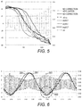
- FIG. 5 is a graph illustrating a relationship between correction methods and correction results of the rectangular signal of the present invention.
- FIG. 6 is a graph illustrating the change in luminance of the polarized light in a case of inputting a drive signal fitted using Hill function to the polarization selection element of the present invention
- FIG. 7 illustrates an example of the fractional function
- FIG. 8 is a graph illustrating an output of the polarized light in a case of applying a drive signal after correction to the polarization selection element of the present invention
- FIG. 9 is a graph illustrating an output of the polarized light in a case of applying a drive signal after correction to the polarization selection element of the present invention.
- FIG. 10 is a graph illustrating the change in luminance of the polarized light of the prior art.
- FIG. 11 is a graph illustrating data of the polarized light of the prior art.
- Embodiment 1 a representative of the rectangular signal correction method of the present invention will be explained.
- FIG. 1 illustrates a configuration example of a polarization analysis apparatus of the present invention.
- FIG. 2 is a graph indicating the output of polarized light in a case of applying a voltage of a rectangular wave before correction to a polarization selection element of the present invention.
- the left vertical axis of the graph of FIG. 2 indicates the voltage
- the right vertical axis indicates the luminance
- the horizontal axis indicates the time.
- a polarization analysis apparatus 10 of the present invention includes a light source 110 , a polarization selection element 120 , an image sensor 130 , and a controller 140 .
- An optical system such as an object lens may also be disposed between a sample 11 and the polarization selection element 120 .
- the light source 110 radiates light to excite the sample 11 to be measured.
- the light source 110 is a laser or the like, for example. Light radiated from the light source 110 is selected in accordance with the type and state of the sample 11 .
- the sample 11 includes a fluorescent substance, excites by the light radiated from the light source 110 , and radiates light.
- the polarization direction of the measurement light that was output by the sample 11 changes depending on the temperature and viscosity of the sample 11 as well as the amounts and types of substances contained in the sample 11 .
- the measurement light in which I ⁇ is larger than I ⁇ is constantly radiated from the sample 11 .
- the polarization selection element 120 is driven by a voltage applied based on the drive signal, and outputs measurement light of a specific polarization direction out of the measurement light radiated from the sample 11 .
- the polarization selection element 120 is disposed between the sample 11 and the image sensor 130 .
- the polarization selection element 120 is made of a liquid crystal panel of a transmissive type and a polarization panel. In the present invention, the liquid crystal panel is a TN-type liquid crystal panel.
- the X axis and Y axis are set in the plane of the polarization selection element 120
- the Z axis is set in the direction perpendicular to the XY plane and parallel to the travelling direction of the measurement light.
- the image sensor 130 is a sensor including a plurality of light-receiving elements such as CCD sensor, CMOS sensor, and photo-diode array.
- the image sensor 130 measures the luminance of the measurement light output from the polarization selection element 120 based on the predetermined light exposure time, and outputs the measurement results as the luminance data.
- the image sensor outputs the luminance data as illustrated in FIG. 11 .
- the controller 140 applies a voltage to the polarization selection element 120 based on the drive signal and controls the light exposure time of the image sensor 130 .
- the controller 140 includes, for example, a computer having a processor and a memory, a power supply that supplies a voltage to the polarization selection element 120 based on the drive signal, and a function generator that controls the light exposure time of the image sensor 130 .
- the controller 140 controls the drive signal and the light exposure time such that the phase relationship between the two remains constant.
- the controller 140 generates control information of the drive signal for obtaining the output of the measurement light with the luminance changing in a sine waveform as illustrated in FIG. 10 , and supplies a voltage to the polarization selection element 120 based on the control information of the drive signal.
- the drive signal oscillates in a cycle of T 1 .
- the cycle of the drive signal synchronizes with the cycle of the output (luminance change) of measurement light.
- the controller 140 divides the cycle T 1 into four sections, and sets each time section T 2-1 , T 2-2 , T 2-3 , and T 2-4 as the light exposure time of the image sensor 130 .
- the controller 140 obtains the luminance data from the image sensor 130 , and calculates the degree of polarization by plugging the luminance into Formula 1 or Formula 2.
- the degree of polarization P can be calculated using Formula 1. If there is no constant relationship between the phase of the measurement light that passes through the polarization selection element 120 and the light-receiving timing (phase) of the measurement light, the degree of polarization P can be calculated using Formula 2.
- a rectangular wave 210 as illustrated in FIG. 2 is used for the drive signal such that the measurement light with the luminance changing in a sine waveform is output, which is indicated by the signal 200 .
- the voltage oscillates between positive and negative, and the absolute value of the voltage changes at cycles.
- the absolute value of the voltage changes at a cycle of T 1 .
- the rectangular wave is also referred to as a rectangular signal.
- the rectangular signal 210 within the range 230 is considered a rectangular signal 210 of one cycle.
- the left end of the range 230 is 0, and the right end thereof is 2n.
- the cycle in which the rectangular signal 210 oscillates between positive and negative (pulse width) is smaller than the cycle T 1 .
- a signal 220 indicates the shape of the luminance change of the measurement light that passes through the liquid crystal panel, which is affected by the delayed response of the liquid crystal panel to the voltage change. As illustrated in FIG. 2 , the signal 220 is offset from the signal 200 . The offset amount is greater in sections of the rectangular signal 210 where the absolute value of the voltage is increasing in response to the change in phase. In the present invention, the section of the rectangular signal 210 where the absolute value of the voltage is increasing in response to the change in phase is referred to as an ascending section of the rectangular signal 210 , and the section of the rectangular signal 210 where the absolute value of the voltage is decreasing in response to the change in phase referred to as a descending section of the rectangular signal 210 .
- the phase in the ascending section of the rectangular signal 210 is from n to 2 n.
- the controller 140 of the present invention corrects the rectangular signal 210 to eliminate the offset, and applies a voltage to the polarization selection element 120 based on the corrected rectangular signal.
- the controller 140 fits a relationship (VT characteristic) between the applied voltage and transmittance of the liquid crystal panel used for the polarization selection element 120 to the sigmoid curve, and then calculates an inverse function representing the voltage with the luminance as a variable.
- VT characteristic the voltage is x
- the luminance is y
- the function representing the luminance y is F(x)
- the inverse function thereof is G(y).
- the controller 140 of the present invention performs the fitting using the Boltzman function of Formula 5, and calculates the inverse function as Formula 6.
- A1, A2, and x0 are adjustable parameters.
- the controller 140 plugs the luminance y at the phase p in the measurement light output model H(p) illustrated in FIG. 10 into the inverse function G(y), thereby calculating the voltage x.
- the measurement light output model H(p) is given by Formula 7.
- the controller 140 calculates the voltage at the phase p of the rectangular signal 210 to realize the luminance H(p) by plugging the luminance H(p) into the variable y in Formula 6.
- the voltage corresponding to the amplitudes of the rectangular signal 210 will also be referred to as the reference voltage.
- the controller 140 performs the same process for each phase.
- the controller 140 holds the information including the calculated reference voltage and the oscillation cycle of the rectangular signal as the control information of the drive signal.
- the oscillation cycle of the rectangular signal is determined in advance.
- the controller 140 calculates the first corrected reference voltage obtained by correcting the reference voltage in the ascending section of the rectangular signal 210 .
- the value obtained by adding a predetermined fixed value to the reference voltage is calculated as the first corrected reference voltage. Examples of the fixed value include “+0.4V.”
- the controller 140 updates the control information of the drive signal based on the calculation results of the first corrected reference voltage.
- FIG. 3 is a graph illustrating the change in luminance of the polarized light in a case of applying a voltage of a rectangular wave after correction to the polarization selection element of the present invention.
- the change in luminance of measurement light that passes through the polarization selection element 120 is represented by a graph such as the signal 260 .
- the offset between the signal 200 and the signal 260 is smaller than the offset between the signal 200 and the signal 220 .
- the controller 140 controls the voltage to be applied to the polarization selection element 120 based on the rectangular signal obtained by correcting the reference voltage in the ascending section of the rectangular signal 210 , and therefore, the change in luminance of the measurement light that passes through the polarization selection element 120 forms an ideal sine wave. As a result, the calculation accuracy of the degree of polarization is improved.
- Embodiment 1 the rectangular signal 210 is corrected only in the ascending sections. In Embodiment 2, the rectangular signal 210 is also corrected in the descending sections. Below, Embodiment 2 will be explained mainly focusing on the differences from Embodiment 1.
- Embodiment 2 The configuration of the polarization analysis apparatus 10 of Embodiment 2 is the same as that of Embodiment 1, and the description will therefore be omitted.
- the controller 140 calculates the second corrected reference voltage obtained by correcting the reference voltage in the descending section of the rectangular signal 210 together with the first corrected reference voltage in (Process 3).
- the value obtained by adding a predetermined fixed value to the reference voltage is calculated as the second corrected reference voltage. Examples of the fixed value include “ ⁇ 0.2V.”
- the voltage is corrected in different manners in the ascending sections and the descending sections of the rectangular signal 210 , and as a result, the change in luminance of the measurement light that passes through the polarization selection element 120 is made closer to an ideal sine wave.
- the controller 140 is configured to uniformly correct the reference voltage in the ascending sections of the rectangular signal 210 . However, when the reference voltage is corrected uniformly, the overshoot occurs as indicated with the region 300 of FIG. 3 .
- the controller 140 is configured to correct the reference voltage in the ascending sections of the rectangular signal 210 so as to suppress the occurrence of the overshoot. Below, Embodiment 3 will be explained mainly focusing on the differences from Embodiment 1.
- Embodiment 3 The configuration of the polarization analysis apparatus 10 of Embodiment 3 is the same as that of Embodiment 1, and the description thereof will therefore be omitted.
- the controller 140 calculates the first corrected reference voltage in which the correction amount gradually changes in accordance with the phase change of the rectangular signal 210 . Specifically, the controller 140 corrects the reference voltage such that the correction amount is greatest at the start of the ascending section of the rectangular signal 210 and then gradually decreases toward the end of the ascending section. That is, the reference voltage is corrected such that the correction amount decreases as the phase increases (corresponding to the phase change).
- FIG. 4 is a diagram illustrating a relationship between the phase and the correction amount of the rectangular signal 210 of the present invention.
- FIG. 5 is a graph illustrating a relationship between the correction methods and the correction results of the rectangular signal of the present invention.
- the vertical axis indicates the voltage
- the horizontal axis indicates the phase.
- the left vertical axis indicates the voltage
- the right vertical axis indicates the luminance
- the horizontal axis indicates the time.
- Embodiment 3 five correction methods are employed. “+0.4 v correction” is the correction method of the rectangular signal 210 described in Embodiment 1.
- the “expG correction” is the correction method to calculate the first corrected reference voltage based on Formula 8.
- G is a parameter used for the correction.
- p is the phase
- V is the reference voltage of the rectangular signal 210 at the phase p
- V′ is the corrected reference voltage at the phase p (first corrected reference voltage).
- V′ V ⁇ exp((2 ⁇ p ) ⁇ G ) (8)
- the “exp0.3′ correction” is the correction method using the same formula as that of “exp0.3,” where the correction is made such that the first corrected reference voltage of 0.9 ⁇ becomes equivalent to the first corrected reference voltage of 0.8 ⁇ .
- the “power of q correction” is the correction method to calculate the first corrected reference voltage based on Formula 9.
- q is a parameter used for the correction.
- V′ V ⁇ (2 ⁇ p ) q (9)
- the problem of overshoot is solved when G is 0.3 or smaller.
- the study on q being greater than 2 and smaller than 10 reveals that the problem of overshoot is more effectively solved when q is 3.5.
- the reference voltage of the ascending sections of the rectangular signal 210 is corrected such that the correction amount for the reference voltage changes gradually depending on the phase change of the rectangular signal 210 , which makes it possible to prevent the problem of overshoot.
- the waveform of the luminance change of the measurement light that passes through the polarization selection element 120 even closer to the sine wave as compared to the case in which the correction is made uniformly.
- Embodiment 4 differs from Embodiment 1 in the calculation method of the function used for fitting the corrected reference voltages (first corrected reference voltage and the second corrected reference voltage). Below, Embodiment 4 will be explained mainly focusing on the differences from Embodiment 1.
- Embodiment 4 The configuration of the polarization analysis apparatus 10 of Embodiment 4 is the same as that of Embodiment 1, and the description thereof will therefore be omitted.
- the function used in (Process 1) differs from that of Embodiment 1.
- the controller 140 of the present invention performs the fitting using the Hill function as in Formula 10, and calculates the inverse function as in Formula 11.
- k and n are adjustable parameters.
- Process 2 is the same as that of Embodiment 1. Specifically, the controller 140 calculates the reference voltage at the phase p of the rectangular signal 210 to realize the luminance H(p) by plugging the output model H(p) of the measurement light illustrated in FIG. 10 into the variable y in Formula 11.
- the offset between the signal 200 and the signal 261 in the region 600 of FIG. 6 indicating a region near the point of the greatest absolute value of the voltage is smaller as compared to the case in which the Boltzmann function is used for fitting.
- a great offset occurs in a region near the point of the smallest absolute value of the voltage of the rectangular signal 251 , and the correction value is added to the reference voltage to eliminate this offset.
- the symmetrical offset between the signal 200 and the signal 261 in the region 600 of FIG. 6 indicating a region near the point of the greatest absolute value of the voltage can be solved by adjusting the parameters k and n in Formula 11.
- a great asymmetrical offset occurs in a region near the point of the smallest absolute value of the voltage of the rectangular signal 251 , and the correction value is added to the reference voltage to eliminate this offset.
- the controller 140 calculates the correction value to be added to the reference voltage in the ascending section of the rectangular signal 251 , using the fractional function with the phase p as a variable.
- the correction value to be added to the reference voltage is calculated using the fractional function of Formula 12.
- K, a, b, c, and d are adjustable parameters.
- FIG. 7 illustrates an example of the fractional function.
- the vertical axis indicates the correction value
- the horizontal axis indicates the value of the variable y.
- the possible parameter values are as follows: a, c, d are each 1, b is 10, and K is 5.
- the controller 140 calculates the corrected reference voltage by adding, to the reference voltage, the correction value derived from the fractional function having the characteristics illustrated in FIG. 7 .
- variable y in Formula 12 is substituted by the phase p.
- the variable y may also be substituted by a value obtained by adding an arbitrary phase ⁇ to the phase p.
- ⁇ is an adjustable parameter.
- FIG. 8 is a graph illustrating an output of the polarized light in a case of applying a drive signal after correction to the polarization selection element of the present invention.
- each region near the point of the smallest absolute value of the voltage in the rectangular signal 252 has a shape indicating the characteristic of the fractional function.
- the offset between the signal 200 and the signal 262 is smaller than the offset between the signal 200 and the signal 261 .
- Embodiment 4 by using the Hill function for fitting and the fractional function for correction, the change in luminance of the measurement light that passes through the polarization selection element 120 can be made even closer to the ideal sine wave efficiently and easily.
- Embodiment 5 differs from Embodiment 1 in using an FFS (fringe field switching) liquid crystal panel. Below, Embodiment 5 will be explained mainly focusing on the differences from Embodiment 1.
- FFS field switching
- FIG. 9 is a graph illustrating the output of the polarized light in a case of applying a voltage corresponding to a rectangular wave before correction to the polarization selection element of the present invention.
- the left vertical axis of the graph of FIG. 9 indicates the voltage
- the right vertical axis indicates the luminance
- the horizontal axis indicates the time.
- the change in luminance of measurement light that passes through the polarization selection element 120 does not coincide with the ideal sine wave.
- controller 140 performs the correction methods described in Embodiments 1 to 4 to eliminate the difference.
- the formulae and parameters to be used can be appropriately modified in accordance with the characteristics of the liquid crystal panel and the like.
- the change in luminance of the polarized light when a voltage corresponding to the rectangular wave before correction is applied to the polarization selection element of the present invention substantially forms a sine wave, and therefore, the controller 140 may correct the offset of the phase instead.
- Embodiment 5 effects similar to those of Embodiments 1 to 4 can be obtained even in the FFS liquid crystal panel.
Landscapes
- Physics & Mathematics (AREA)
- Health & Medical Sciences (AREA)
- General Physics & Mathematics (AREA)
- Chemical & Material Sciences (AREA)
- Immunology (AREA)
- Spectroscopy & Molecular Physics (AREA)
- Biochemistry (AREA)
- Analytical Chemistry (AREA)
- Life Sciences & Earth Sciences (AREA)
- General Health & Medical Sciences (AREA)
- Nuclear Medicine, Radiotherapy & Molecular Imaging (AREA)
- Pathology (AREA)
- Nonlinear Science (AREA)
- Optics & Photonics (AREA)
- Crystallography & Structural Chemistry (AREA)
- Chemical Kinetics & Catalysis (AREA)
- Investigating Or Analysing Materials By Optical Means (AREA)
- Investigating, Analyzing Materials By Fluorescence Or Luminescence (AREA)
- Liquid Crystal (AREA)
Abstract
Description
Formula 8
V′=V×exp((2−p)×G) (8)
Formula 9
V′=V×(2−p)q (9)
As illustrated in
Claims (16)
Formula 3
V′=V×exp((2−p)×G) (3)
Formula 4
G≤0.3 (4)
Formula 5
V′=V×(2−p)q (5)
Formula 6
2<q<10 (6)
Formula 7
q≈3.5 (7)
Formula 10
V′=V×exp((2−p)×G) (10)
Formula 11
G≤0.3 (11)
Formula 12
V′=V×(2−p)q (12)
Formula 13
2<q<10 (13)
Formula 14
q≈3.5 (14)
Applications Claiming Priority (2)
| Application Number | Priority Date | Filing Date | Title |
|---|---|---|---|
| JP2018-066892 | 2018-03-30 | ||
| JP2018066892A JP7174528B2 (en) | 2018-03-30 | 2018-03-30 | Polarization analyzer and control method for polarization analyzer |
Publications (2)
| Publication Number | Publication Date |
|---|---|
| US20190302023A1 US20190302023A1 (en) | 2019-10-03 |
| US10508991B2 true US10508991B2 (en) | 2019-12-17 |
Family
ID=68054204
Family Applications (1)
| Application Number | Title | Priority Date | Filing Date |
|---|---|---|---|
| US16/371,403 Active US10508991B2 (en) | 2018-03-30 | 2019-04-01 | Polarization analysis apparatus and control method of polarization analysis apparatus |
Country Status (3)
| Country | Link |
|---|---|
| US (1) | US10508991B2 (en) |
| JP (1) | JP7174528B2 (en) |
| CN (1) | CN110320185B (en) |
Citations (2)
| Publication number | Priority date | Publication date | Assignee | Title |
|---|---|---|---|---|
| US20050200941A1 (en) * | 2003-08-08 | 2005-09-15 | Yao X. S. | Generation and analysis of state of polarization using tunable optical polarization rotators |
| WO2015174332A1 (en) | 2014-05-16 | 2015-11-19 | 国立大学法人東京工業大学 | Polarization analyzer |
Family Cites Families (10)
| Publication number | Priority date | Publication date | Assignee | Title |
|---|---|---|---|---|
| JPS51129279A (en) * | 1975-05-02 | 1976-11-10 | Nippon Kogaku Kk <Nikon> | Polarizing analyzer |
| JP3346843B2 (en) * | 1993-06-30 | 2002-11-18 | 株式会社東芝 | Liquid crystal display |
| JP2004212598A (en) * | 2002-12-27 | 2004-07-29 | Sharp Corp | Conversion device, correction circuit, drive device, display device, inspection device, and display method |
| US7466471B2 (en) * | 2003-03-12 | 2008-12-16 | General Photonics Corporation | Optical instrument and measurements using multiple tunable optical polarization rotators |
| US7436569B2 (en) * | 2003-03-12 | 2008-10-14 | General Photonics Corporation | Polarization measurement and self-calibration based on multiple tunable optical polarization rotators |
| JP4343743B2 (en) * | 2004-03-19 | 2009-10-14 | シチズンホールディングス株式会社 | Optical rotation measuring device and concentration measuring device |
| JP5013581B2 (en) * | 2005-05-26 | 2012-08-29 | ルネサスエレクトロニクス株式会社 | Display device, controller driver, and display panel driving method |
| US7573579B2 (en) * | 2006-10-12 | 2009-08-11 | Duke University | Coded aperture imaging photopolarimetry |
| KR101320018B1 (en) * | 2007-12-04 | 2013-10-18 | 삼성디스플레이 주식회사 | Light source and driving method the same and display device having the same |
| WO2017170688A1 (en) * | 2016-03-31 | 2017-10-05 | 大日本印刷株式会社 | Light control system, light control device, light control film, method for driving light control film, and vehicle |
-
2018
- 2018-03-30 JP JP2018066892A patent/JP7174528B2/en active Active
-
2019
- 2019-03-26 CN CN201910230708.9A patent/CN110320185B/en active Active
- 2019-04-01 US US16/371,403 patent/US10508991B2/en active Active
Patent Citations (4)
| Publication number | Priority date | Publication date | Assignee | Title |
|---|---|---|---|---|
| US20050200941A1 (en) * | 2003-08-08 | 2005-09-15 | Yao X. S. | Generation and analysis of state of polarization using tunable optical polarization rotators |
| WO2015174332A1 (en) | 2014-05-16 | 2015-11-19 | 国立大学法人東京工業大学 | Polarization analyzer |
| US20170074796A1 (en) * | 2014-05-16 | 2017-03-16 | Tohoku University | Light polarization analyzer |
| US9719927B2 (en) * | 2014-05-16 | 2017-08-01 | Tohoku University | Light polarization analyzer |
Also Published As
| Publication number | Publication date |
|---|---|
| CN110320185B (en) | 2024-02-09 |
| JP7174528B2 (en) | 2022-11-17 |
| JP2019178891A (en) | 2019-10-17 |
| US20190302023A1 (en) | 2019-10-03 |
| CN110320185A (en) | 2019-10-11 |
Similar Documents
| Publication | Publication Date | Title |
|---|---|---|
| EP2015133B1 (en) | Athermalized birefringent filter apparatus and method | |
| US20160351139A1 (en) | Adjusting method of display parameter and liquid crystal display system | |
| CN112444508A (en) | Fluorescent image analysis device | |
| JP5745629B2 (en) | Exothermic point detection method and exothermic point detector | |
| US10508991B2 (en) | Polarization analysis apparatus and control method of polarization analysis apparatus | |
| US20080297869A1 (en) | Oscillator device and drive control method for oscillation system of oscillator device | |
| KR20140075757A (en) | Method for detecting heat generation points and device for detecting heat generate points | |
| CN114397778A (en) | Display heating compensation method, device and system | |
| US10176743B2 (en) | Method for adjusting color temperature and device | |
| US9719927B2 (en) | Light polarization analyzer | |
| US20180205919A1 (en) | Projector device and method for correcting color in projector device | |
| US20240210601A1 (en) | Variable focal length lens device and variable focal length lens control method | |
| US10260901B2 (en) | Method for optimizing the switch-on time of a coriolis gyroscope and coriolis gyroscope suitable thereof | |
| EP3944609A1 (en) | Image sensor | |
| US5247387A (en) | Method and device for driving electro-optical light shutter | |
| US10379043B2 (en) | Measuring path delay through a liquid-crystal variable retarder at non-uniform retardance intervals | |
| JP2009168603A (en) | Apparatus and method for measuring liquid crystal response time | |
| US20060215797A1 (en) | Specific phase position detection circuit and method of the same | |
| US20180374544A1 (en) | Wide range zero temperature coefficient oscillators and related devices and methods | |
| EP3975540A1 (en) | Image sensor | |
| JP4064329B2 (en) | Method and apparatus for measuring viscosity coefficient of liquid crystal | |
| JP2016181184A (en) | Control device, optical device, control method, and program | |
| JP2021193431A (en) | Focal distance variable lens device and control method therefor | |
| JP2002140047A (en) | LCD panel drive | |
| KR101686660B1 (en) | Apparatus and method for controlling common voltage of liquid crystal display device |
Legal Events
| Date | Code | Title | Description |
|---|---|---|---|
| AS | Assignment |
Owner name: TIANMA JAPAN, LTD., JAPAN Free format text: ASSIGNMENT OF ASSIGNORS INTEREST;ASSIGNOR:MIZOKUCHI, CHIKAAKI;REEL/FRAME:048754/0093 Effective date: 20190108 |
|
| FEPP | Fee payment procedure |
Free format text: ENTITY STATUS SET TO UNDISCOUNTED (ORIGINAL EVENT CODE: BIG.); ENTITY STATUS OF PATENT OWNER: LARGE ENTITY |
|
| STPP | Information on status: patent application and granting procedure in general |
Free format text: DOCKETED NEW CASE - READY FOR EXAMINATION |
|
| STPP | Information on status: patent application and granting procedure in general |
Free format text: NOTICE OF ALLOWANCE MAILED -- APPLICATION RECEIVED IN OFFICE OF PUBLICATIONS |
|
| STPP | Information on status: patent application and granting procedure in general |
Free format text: PUBLICATIONS -- ISSUE FEE PAYMENT VERIFIED |
|
| STCF | Information on status: patent grant |
Free format text: PATENTED CASE |
|
| MAFP | Maintenance fee payment |
Free format text: PAYMENT OF MAINTENANCE FEE, 4TH YEAR, LARGE ENTITY (ORIGINAL EVENT CODE: M1551); ENTITY STATUS OF PATENT OWNER: LARGE ENTITY Year of fee payment: 4 |