US10508526B2 - Fracing plug - Google Patents
Fracing plug Download PDFInfo
- Publication number
- US10508526B2 US10508526B2 US15/579,918 US201715579918A US10508526B2 US 10508526 B2 US10508526 B2 US 10508526B2 US 201715579918 A US201715579918 A US 201715579918A US 10508526 B2 US10508526 B2 US 10508526B2
- Authority
- US
- United States
- Prior art keywords
- retaining body
- arms
- slip
- slip arms
- plug
- Prior art date
- Legal status (The legal status is an assumption and is not a legal conclusion. Google has not performed a legal analysis and makes no representation as to the accuracy of the status listed.)
- Active
Links
- 238000004181 pedogenesis Methods 0.000 claims abstract description 4
- 239000000463 material Substances 0.000 claims description 10
- 239000012530 fluid Substances 0.000 claims description 8
- 239000010959 steel Substances 0.000 claims description 4
- 229910000838 Al alloy Inorganic materials 0.000 claims description 2
- 229910000851 Alloy steel Inorganic materials 0.000 claims description 2
- 238000004519 manufacturing process Methods 0.000 description 10
- 238000007789 sealing Methods 0.000 description 8
- 238000000034 method Methods 0.000 description 7
- 239000004215 Carbon black (E152) Substances 0.000 description 5
- 229930195733 hydrocarbon Natural products 0.000 description 5
- 150000002430 hydrocarbons Chemical class 0.000 description 5
- 230000015572 biosynthetic process Effects 0.000 description 3
- 238000005755 formation reaction Methods 0.000 description 3
- 239000011435 rock Substances 0.000 description 3
- 239000004576 sand Substances 0.000 description 3
- 239000004696 Poly ether ether ketone Substances 0.000 description 2
- 229910000831 Steel Inorganic materials 0.000 description 2
- 229920002530 polyetherether ketone Polymers 0.000 description 2
- 229920001343 polytetrafluoroethylene Polymers 0.000 description 2
- 239000004810 polytetrafluoroethylene Substances 0.000 description 2
- 241000191291 Abies alba Species 0.000 description 1
- 229920000459 Nitrile rubber Polymers 0.000 description 1
- -1 Polytetrafluoroethylene Polymers 0.000 description 1
- 229920006172 Tetrafluoroethylene propylene Polymers 0.000 description 1
- XAGFODPZIPBFFR-UHFFFAOYSA-N aluminium Chemical compound [Al] XAGFODPZIPBFFR-UHFFFAOYSA-N 0.000 description 1
- 229910052782 aluminium Inorganic materials 0.000 description 1
- 239000002131 composite material Substances 0.000 description 1
- 239000002360 explosive Substances 0.000 description 1
- 238000005304 joining Methods 0.000 description 1
- 150000002825 nitriles Chemical class 0.000 description 1
- 238000003825 pressing Methods 0.000 description 1
- 238000005086 pumping Methods 0.000 description 1
- 238000010008 shearing Methods 0.000 description 1
- 238000003892 spreading Methods 0.000 description 1
- 230000004936 stimulating effect Effects 0.000 description 1
- 239000000126 substance Substances 0.000 description 1
- XLYOFNOQVPJJNP-UHFFFAOYSA-N water Substances O XLYOFNOQVPJJNP-UHFFFAOYSA-N 0.000 description 1
Images


Classifications
-
- E—FIXED CONSTRUCTIONS
- E21—EARTH DRILLING; MINING
- E21B—EARTH DRILLING, e.g. DEEP DRILLING; OBTAINING OIL, GAS, WATER, SOLUBLE OR MELTABLE MATERIALS OR A SLURRY OF MINERALS FROM WELLS
- E21B33/00—Sealing or packing boreholes or wells
- E21B33/10—Sealing or packing boreholes or wells in the borehole
- E21B33/12—Packers; Plugs
- E21B33/129—Packers; Plugs with mechanical slips for hooking into the casing
- E21B33/1293—Packers; Plugs with mechanical slips for hooking into the casing with means for anchoring against downward and upward movement
-
- E—FIXED CONSTRUCTIONS
- E21—EARTH DRILLING; MINING
- E21B—EARTH DRILLING, e.g. DEEP DRILLING; OBTAINING OIL, GAS, WATER, SOLUBLE OR MELTABLE MATERIALS OR A SLURRY OF MINERALS FROM WELLS
- E21B43/00—Methods or apparatus for obtaining oil, gas, water, soluble or meltable materials or a slurry of minerals from wells
- E21B43/25—Methods for stimulating production
- E21B43/26—Methods for stimulating production by forming crevices or fractures
-
- E—FIXED CONSTRUCTIONS
- E21—EARTH DRILLING; MINING
- E21B—EARTH DRILLING, e.g. DEEP DRILLING; OBTAINING OIL, GAS, WATER, SOLUBLE OR MELTABLE MATERIALS OR A SLURRY OF MINERALS FROM WELLS
- E21B33/00—Sealing or packing boreholes or wells
- E21B33/10—Sealing or packing boreholes or wells in the borehole
- E21B33/12—Packers; Plugs
- E21B33/1208—Packers; Plugs characterised by the construction of the sealing or packing means
-
- E—FIXED CONSTRUCTIONS
- E21—EARTH DRILLING; MINING
- E21B—EARTH DRILLING, e.g. DEEP DRILLING; OBTAINING OIL, GAS, WATER, SOLUBLE OR MELTABLE MATERIALS OR A SLURRY OF MINERALS FROM WELLS
- E21B33/00—Sealing or packing boreholes or wells
- E21B33/10—Sealing or packing boreholes or wells in the borehole
- E21B33/13—Methods or devices for cementing, for plugging holes, crevices, or the like
- E21B33/134—Bridging plugs
-
- E—FIXED CONSTRUCTIONS
- E21—EARTH DRILLING; MINING
- E21B—EARTH DRILLING, e.g. DEEP DRILLING; OBTAINING OIL, GAS, WATER, SOLUBLE OR MELTABLE MATERIALS OR A SLURRY OF MINERALS FROM WELLS
- E21B34/00—Valve arrangements for boreholes or wells
- E21B34/06—Valve arrangements for boreholes or wells in wells
- E21B34/063—Valve or closure with destructible element, e.g. frangible disc
Definitions
- the present invention relates to hydrocarbon production in general and in particular to a method and apparatus for locating a fracturing plug within a well.
- hydraulic fracturing is a process of stimulating a hydrocarbon producing well by fracturing the surrounding rock with a hydraulically pressurized fluid of water, sand and chemicals.
- fracing it is commonly necessary to isolate each zone so as to only provide the pressurized fluid and sand to the desired location within the well. This is due to the potential for the well to be quite long and therefore the pumping and material required to therefore frac the entire well string would be too large.
- One common method of splitting the well up into the manageable zones is to provide a plug below the zone to be fraced and thereafter perforating the well bore liner in that zone with an explosive or the like. Thereafter the pressurized fluid and sand may be pumped to that location to perform the frac. This process may be repeated in successive steps upward from the bottom of the well to successively frac each zone that is desired.
- One conventional type of plug is a ring or seat which may be engaged upon the interior of the well bore. Thereafter a ball may be dropped to be engaged upon the seat so as to seal the wellbore.
- an apparatus for use in forming a plug during hydraulic fracturing of a subterranean soil formation comprising a top tubular retaining body extending between top and bottom ends and having a frustoconical outer surface extending from the bottom end thereof.
- the apparatus further includes a plurality of slip arms located around the outer surface of the retaining body, each slip arm extending between top and bottom ends and having an inner surface extending from the top end corresponding to the outer surface of the retaining body and an exterior surface adapted to frictionally engage a wellbore; and a seal element located around the outer surface of the retaining body above the plurality of slip arms adapted to be displaced towards the top end of the retaining body by the plurality of slip arms so as to seal an annulus between the retaining body and the wellbore.
- the outer surface of the retaining body may be formed of a plurality of alternating angled and horizontal sections.
- the inner surface of the plurality of slip arms may include a plurality of alternating angled and horizontal sections adapted to correspond to the outer surface of the retaining body.
- the retaining body may include a central bore therethrough.
- the central bore may form a ball seat adapted to retain a ball thereon.
- the central bore may include a slidably movable plug therethrough.
- the slidably movable plug may engage upon the plurality of slip arms to draw the plurality of slip arms onto the outer surface of the retaining body.
- the slidably movable plug may include a bottom expanded portion having a larger diameter than the plurality of slip arms.
- the slidably movable plug may include a top plug adapted to be spaced apart from a seat in the retaining body as the plurality of slip arms are drawn over the retaining body.
- the slidably movable plug may be operable to slidably shift up and down so as to seal and unseal the top plug against the seat so as to permit fluid flow up the wellbore and prevent fluid flow therepast down the wellbore.
- the plurality of slip arms may extend from a ring surrounding the retaining body adjacent to the seal element.
- the plurality of slip arms may include tabs extending from the bottom end thereof in a direction substantially parallel to a central axis of the retaining body.
- the tabs may include bores adapted to pass a fastener therethrough for securing to a setting tool within the retaining body.
- the apparatus may further comprise a selectably expandable ring surrounding the plurality of slip arms so as to retain the plurality of slip arms at a retracted position until expanded by a setting tool.
- the selectably expandable ring may include a gap therethrough so as to permit radial expansion of the selectably expandable ring.
- the selectably expandable ring may include a frangible portion so as to permit radial expansion of the selectably expandable ring.
- the selectably expandable ring may include a narrowed portion so as to permit radial expansion of the selectably expandable ring after breaking the narrowed portion.
- the plurality of slip arms may be formed of a selectably dissolvable material.
- the plurality of slip arms may be formed of a material selected from the group consisting of steel and aluminum alloys.
- the plurality of slip arms may include well bore engaging plugs imbedded therein.
- the apparatus may further comprise a setting tool adapted to pass through the central bore of the retaining body.
- the setting tool may comprise an exterior portion adapted to bear upon a top edge of the retaining body and an interior portion adapted to engage upon a bottom edge of the plurality of slip arms so as to draw the plurality of slip arms towards the retaining portion.
- the interior portion may include pull arms adapted to engage the bottom edge of the plurality of slip arms.
- the pull arms may include an inclined surface adapted to engage a corresponding inclined surface of the plurality of slip arms.
- the pull arms may be longitudinally cantilevered parallel to the axis of the retaining body.
- the interior portion of the setting tool may include a transfer sleeve therearound having a portion adapted to engage upon distal ends of the pull arms to retain the pull arms at a radially expanded position so as to engage upon the plurality of slip arms.
- the transfer sleeve may be secured to the interior portion with a frangible connector wherein after the frangible connector is broken, the transfer sleeve is operable to be shifted downward thereby permitting the pull arms to be moved radially inward so as to permit removal of the setting tool.
- FIG. 1 is a cross sectional view of a well bore having a plurality of plugs located therein associated with each zone to be utilized for sealing and hydraulically fracturing each zone.
- FIG. 2 is a perspective view of one of the plugs for use in the well bore of FIG. 1 .
- FIG. 3 is a perspective view of the plug of FIG. 1 with a setting tool located therein.
- FIG. 4 is a cross sectional view of the plug and setting tool of FIG. 3 at a first or run in position.
- FIG. 5 is a cross sectional view of the plug and setting tool of FIG. 3 at a second or initial setting position.
- FIG. 6 is a cross sectional view of the plug and setting tool of FIG. 3 at a third or engaged position.
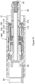
- FIG. 7 is a cross sectional view of the plug and setting tool of FIG. 3 at a fourth or released position.
- FIG. 8 is a cross sectional view of the cone of the plug of FIG. 2 .
- FIG. 9 is an exploded view of the plug of FIG. 2 .
- FIG. 10 is an exploded view perspective view of a plug for use in the well bore of FIG. 1 .
- FIG. 11 is a cross sectional view of the plug of FIG. 10 and its associated setting tool at a first or run in position.
- FIG. 12 is a cross sectional view of the plug of FIG. 10 and its associated setting tool at a second or setting position.
- FIG. 13 is a cross sectional view of the plug of FIG. 10 and its associated setting tool at a third or release position.
- FIG. 14 is an exploded perspective view of a further embodiment of a plug for use in the well bore of FIG. 1 .
- FIG. 15 is a perspective view of the plug of FIG. 14 with a check valve and setting tool located therein.
- FIG. 16 is a cross sectional view of the plug and check valve of FIG. 15 within a well at a first or run in position.
- FIG. 17 is a cross sectional view of the plug and check valve of FIG. 15 within a well at a second or engaged position.
- FIG. 18 is a cross sectional view of the plug and check valve of FIG. 15 within a well at a third or fracing position.
- FIG. 19 is a cross sectional view of the plug and check valve of FIG. 15 within a well at a fourth or installed flowing position.
- a wellbore 10 is drilled into the ground 8 to a production zone 6 by known methods.
- the production zone 6 may contain a horizontally extending hydrocarbon bearing rock formation or may span a plurality of hydrocarbon bearing rock formations such that the wellbore 10 has a path designed to cross or intersect each formation.
- the wellbore includes a vertical section 12 having a wellhead valve assembly or Christmas tree 14 at a top end thereof and a bottom or production section 16 which may be horizontal, vertically or angularly oriented relative to the horizontal located within the production zone 6 .
- the production section 16 is separated into one or more zones 18 with fracing plug seats 20 located therebetween for subsequent fracing.
- a fracing plug seat according to a first embodiment of the present invention is illustrated generally at 20 .
- the fracing plug seat 20 extends between first and second ends 22 and 24 , respectively, and is formed of a top tubular retaining body 30 at the first end 22 , a plurality of slip arms 50 around the retaining body 30 forming the second end 24 of the seat, and a seal 70 located therebetween.
- the retaining body 30 comprises a tubular body extending between first and second ends 32 and 34 , respectively.
- the retaining body 30 includes a cone section 36 extending from the second end 34 around the exterior surface thereof.
- the cone section 36 is adapted to engage with and displace the slip arms 50 outwardly as will be more fully described below.
- the interior of the retaining body 30 includes a central passage 38 extending therethrough.
- the central passage is narrower proximate to the second end 34 than it is near the first end and includes a profiled section 40 adapted to receive a dropped ball (not shown) thereon as is commonly known.
- the cone section 36 may be formed of alternating angled and horizontal portions 42 and 44 , respectively.
- the cone section 36 may have a constant profile.
- the alternating angled and horizontal portions 42 and 44 assist with the engagement of the slip arms 50 upon the wellbore 10 by spreading the length of contact over a longer distance without reducing the angle movement of the slip arms 50 on the cone section 36 .
- the horizontal portions 44 may be substantially aligned with the axis of the plug seat 20 wherein the angled portions may have a frustoconical shape having a slip angle generally indicated at 43 relative to the central axis of the plug seat 20 . In practice, it has been found that a slip angle of between 5 and 30 degrees may be useful.
- the retaining body 30 may include an annular groove 130 in an interior surface thereof adapted to engage upon a ridge or other protrusion (not shown) extending from an outer portion extension 85 as illustrated in FIG. 7 .
- annular groove 130 will be useful to prevent movement of the retaining body 30 during run in as will be further described below.
- the slip arms 50 are secured to a ring 56 at a first end 52 thereof.
- Each of the slip arms 50 extends to a second end 54 having a tab 64 with a bore 66 therethrough.
- the slip arms 50 include a well bore engaging surface 60 on an outer surface thereof and an inner cone engaging surface 62 on an interior thereof.
- the inner cone engaging surface 62 may be formed of alternating angled and horizontal portions sized and shaped to correspond to the cone section 36 as described above.
- the slip arms 50 and the ring 56 may be formed of any suitable materials as are commonly known.
- the ring 56 may be formed of a malleable material such as, by way of non-limiting example, cold steel so as to be deformable as the slip arms 50 are displaced over the retaining body 30 .
- the seal 70 comprises a ring member extending between first and second ends 72 and 74 , respectively, having a central bore 76 therethrough.
- the central bore 76 is sized to be received around the cone section 36 of the retaining body 30 at a first or run in position.
- the seal 70 may be formed of any suitable material as is commonly known in the art such as, by way of non-limiting example, VitonTM, nitrile, Polytetrafluoroethylene (PTFE),
- PEEK Polyetheretherketone
- HNBR Hydrogenated Nitrile Butadiene Rubber
- AFLAS® AFLAS®
- Kalrez® Kalrez®
- a setting tool 80 of any conventional type may be utilized having an outer portion 84 adapted to engage upon and press the retaining body 30 towards the second end 24 of the fracing plug seat 20 and an inner portion 82 adapted to engage the slip arms 50 and draw them towards the first end 22 of the fracing plug seat 20 so as to draw or slide the slip arms 50 and seal 70 over the cone section 36 thereby expanding them into contact with the wall of the well bore 10 .
- the setting tool 80 includes a plurality of setting tool pull arms 110 extending threrealong at a position under the slip arms 50 of the fracing plug seat 20 .
- the setting tool pull arms 110 include an inclined surface 112 in an orientation such that upward movement of the setting tool pull arms 110 will bias the slip arms 50 in an outward direction.
- the inner portion 82 of the setting tool 80 includes a transfer sleeve 88 secured thereto with an end plug 90 .
- the end plug 90 includes a necked portion 92 adapted to be fractured so as to disengage the transfer sleeve 88 from the inner portion 82 .
- the transfer sleeve 88 further includes an annular ridge 87 extending inwardly at a top end thereof adapted to engage upon an outwardly extending annular ridge 89 at the distal end of the inner portion 82 .
- the transfer sleeve 88 may be secured to the slip arms 50 with set pins 86 or other frangible fasteners as are commonly known being passed through the bores 66 . As illustrated in FIG. 4 , set pins 86 extend into the transfer sleeve 88 through the setting tool pull arms 110 and prevent the slip arms 50 from movement prior to breaking such that the transfer sleeve 88 is located thereunder preventing inward deflection of the setting tool pull arms 110 .
- the fracing plug seat 20 and setting tool 80 may be secured to each other and run into the well bore 10 in the position shown in FIG. 4 with the slip arms 50 retracted and the seal 70 around the cone section 36 above the slip arms 50 .
- the inner portion 82 and outer portion 84 of the setting tool 80 may be drawn towards each other so as to move the retaining body 30 and the slip arms 50 towards each other in a direction generally indicated at 100 as illustrated in FIG. 6 .
- Continued movement of the inner and outer portions 82 and 84 of the setting tool continue to press the seal 70 up the cone section 36 to be between the retaining body 30 and the well bore 10 as illustrated in FIG.
- a user may then pull upwardly on both the inner and outer portions 82 and 84 to retract the setting tool 80 wherein the setting tool pull arms 110 are permitted to bias inwardly as the setting tool passes the slip arms 50 as there is no longer an object preventing such inward deflection.
- the alternate fracing plug seat 300 is formed in a similar manner as described above but also includes a retaining ring 310 surrounding the slip arms 350 proximate to a second end 354 thereof, maintained in place around the slip arms 350 with at least one retaining screw 312 .
- the retaining ring 310 includes a frangible narrow portion 314 so as to permit the retaining ring 310 to expand and fracture as the slip arms 350 are extended as set out above.
- the slip arms 350 may include a plurality of bore engagement plugs 360 therein extending from the top surface thereof to facilitate engagement upon the well bore 10 wall.
- the slip arms 350 are secured to a ring 356 at a first end 352 thereof.
- the slip arms extend from a slip arm first end 362 with a gap 364 between the ring 356 and the slip arm first end 362 .
- Longitudinal slots 366 extend from the gap 364 past the slip arm first end 362 defining narrow slip arm connections 358 therebetween.
- the slip arm first end 362 pushes up on towards the ring 356 , collapsing the gap 358 thereby aiding the ring 356 to push the seal 70 up the cone section 36 .
- the narrow slip arm connections 358 deform as they move up the cone section 36 .
- the alternative fracing plug seat 200 is formed in a similar manner but also includes a slip engagement ring 210 surrounding the slip arms 250 .
- the slip arms 250 may include external threading 212 therearound adapted to engage with corresponding internal threading 214 on the slip engagement ring 210 .
- the slip engagement ring 210 also includes external ridges therearound to facilitate engagement upon the well bore 10 wall.
- the slip engagement ring 210 includes a split 218 or gap therearound so as to permit the slip engagement ring 210 to expand as the slip arms 250 are extended as set out above.
- the slip engagement ring 210 includes first and second longitudinal slots 220 and 222 , respectively with an annular slot 224 extending therebetween.
- the first and second longitudinal slots 220 and 222 are separated by a distance selected to be larger than the increased diameter of the slip engagement ring when expanded by the slip arms 250 so as to provide a continuous outer surface at such position.
- the first and second longitudinal slots 220 and 222 may also be connected by a frangible portion or tab (not shown) extending thereacross so as to prevent expansion of the slip engagement ring until a sufficiently large enough force is applied thereto by the slip arms 250 .
- a retaining ring 226 may also be provided to retain the slip engagement ring 210 upon the slip arms 250 .
- the setting tool pull arms 110 may include an annular lip 114 extending therefrom which is positioned and shaped to engage a corresponding annular groove 116 on an annular extension 118 of the transfer sleeve 88 .
- the annular groove 116 may receive the annular lip 114 therein wherein the annular extension 118 engages under the setting tool pull arms 110 .
- the setting tool pull arms 110 are prevented from radially compressing or expanding as set out above to be useful to extend the slip arms 250 while permitting the setting tool pull arms 110 to retract after disengaging therefrom as set out above.
- a fracing plug seat 300 is illustrated with a check valve 370 therein.
- the check valve 370 extends between first and second ends, 372 and 374 , respectively.
- a check valve setting tool 376 is adapted to engage upon the first end 22 of the retaining body 30 with the first end 372 of the check valve 370 therein.
- the second end 374 of the check valve 370 includes a bottom engagement cone portion 378 , with an inclined surface 380 in an orientation such that upward movement of the bottom engagement cone portion 378 will bias the slip arms 350 in an outward direction, similar to the inclined surface 112 of the setting tool pull arms 110 as described above.
- the check valve 370 may be formed of any suitable material, as is commonly known, such as, by way of non-limiting example, steel, aluminum, composite or dissolvable materials.
- the check valve 370 includes a frangible protrusion 382 at the first end 372 joined to a top sealing cone portion 386 with a neck portion 384 therebetween.
- An inner plug portion 388 extends from the top sealing cone portion 386 and includes a central connecting body 390 with a plurality of radial extending arms 392 joining the central connecting body 390 with the tubular inside surface of the bottom engagement cone portion 378 , centering the check valve 370 within the fracing plug seat 300 and forming a divided passage 404 therethrough, as illustrated in FIG. 19 .
- the retaining body 30 includes an inclined inner surface 31 adapted to engage with an inclined bottom surface 394 of the top sealing cone portion 386 , forming a seal therebetween.
- the fracing plug seat 300 is secured to the check valve 370 with set pins 396 .
- the assembly is run into the well bore 10 in the position shown in FIG. 16 with the slip arms 350 retracted and the seal 70 around the cone section 36 above the slip arms 350 .
- the check valve 370 is drawn upwards in a direction generally indicated at 400 , while a force is applied to the check valve setting tool 376 in a direction generally indicated at 402 , shearing the set pins 396 as the check valve 370 moves upward within the check valve setting tool 376 .
- FIGS. 18 and 19 illustrate the check valve 370 with fracing plug seat 300 installed in a well bore 10 following removal of the frangible protrusion 382 and check valve setting tool 376 .
- the check valve 370 installed with the fracing plug seat 300 allows for flow from the production zone 6 through the well bore 10 , freely lifting the check valve 370 as illustrated in FIG. 19 , with production flow passing through the check valve 370 through the divided passage 404 and around the top sealing cone portion 386 .
- FIG. 18 when fracing, fluid pressure is applied into the well bore 10 , thereby forcing the top sealing cone portion 386 down such that the inclined bottom surface 394 of the top sealing cone portion 386 engages upon the inclined inner surface 31 of the retaining body 30 , sealing off the lower sections of the well bore 10 .
Abstract
Description
Claims (25)
Priority Applications (2)
| Application Number | Priority Date | Filing Date | Title |
|---|---|---|---|
| US15/579,918 US10508526B2 (en) | 2016-05-06 | 2017-05-05 | Fracing plug |
| US16/705,804 US11162345B2 (en) | 2016-05-06 | 2019-12-06 | Fracing plug |
Applications Claiming Priority (3)
| Application Number | Priority Date | Filing Date | Title |
|---|---|---|---|
| US201662332948P | 2016-05-06 | 2016-05-06 | |
| US15/579,918 US10508526B2 (en) | 2016-05-06 | 2017-05-05 | Fracing plug |
| PCT/CA2017/050555 WO2017190255A1 (en) | 2016-05-06 | 2017-05-05 | Fracing plug |
Related Parent Applications (1)
| Application Number | Title | Priority Date | Filing Date |
|---|---|---|---|
| PCT/CA2017/050555 A-371-Of-International WO2017190255A1 (en) | 2016-05-06 | 2017-05-05 | Fracing plug |
Related Child Applications (1)
| Application Number | Title | Priority Date | Filing Date |
|---|---|---|---|
| US16/705,804 Continuation US11162345B2 (en) | 2016-05-06 | 2019-12-06 | Fracing plug |
Publications (2)
| Publication Number | Publication Date |
|---|---|
| US20190048698A1 US20190048698A1 (en) | 2019-02-14 |
| US10508526B2 true US10508526B2 (en) | 2019-12-17 |
Family
ID=59309021
Family Applications (2)
| Application Number | Title | Priority Date | Filing Date |
|---|---|---|---|
| US15/579,918 Active US10508526B2 (en) | 2016-05-06 | 2017-05-05 | Fracing plug |
| US16/705,804 Active US11162345B2 (en) | 2016-05-06 | 2019-12-06 | Fracing plug |
Family Applications After (1)
| Application Number | Title | Priority Date | Filing Date |
|---|---|---|---|
| US16/705,804 Active US11162345B2 (en) | 2016-05-06 | 2019-12-06 | Fracing plug |
Country Status (6)
| Country | Link |
|---|---|
| US (2) | US10508526B2 (en) |
| CN (1) | CN109415929B (en) |
| AU (2) | AU2017260712B2 (en) |
| CA (1) | CA2966136C (en) |
| RU (1) | RU2734968C2 (en) |
| WO (1) | WO2017190255A1 (en) |
Cited By (6)
| Publication number | Priority date | Publication date | Assignee | Title |
|---|---|---|---|---|
| US11162345B2 (en) | 2016-05-06 | 2021-11-02 | Schlumberger Technology Corporation | Fracing plug |
| US11401790B2 (en) | 2020-08-04 | 2022-08-02 | Halliburton Energy Services, Inc. | Completion systems, methods to produce differential flow rate through a port during different well operations, and methods to reduce proppant flow back |
| US11414958B2 (en) | 2020-08-04 | 2022-08-16 | Halliburton Energy Services, Inc. | Proppant flow back restriction systems, methods to reduce proppant flow back, and methods to deploy a screen over a port |
| US11608704B2 (en) | 2021-04-26 | 2023-03-21 | Solgix, Inc | Method and apparatus for a joint-locking plug |
| US11661813B2 (en) | 2020-05-19 | 2023-05-30 | Schlumberger Technology Corporation | Isolation plugs for enhanced geothermal systems |
| US11761297B2 (en) | 2021-03-11 | 2023-09-19 | Solgix, Inc | Methods and apparatus for providing a plug activated by cup and untethered object |
Families Citing this family (7)
| Publication number | Priority date | Publication date | Assignee | Title |
|---|---|---|---|---|
| AR112578A1 (en) | 2017-07-26 | 2019-11-13 | Schlumberger Technology Bv | FRACTURING DEVIATOR |
| WO2019152039A1 (en) * | 2018-02-01 | 2019-08-08 | Halliburton Energy Services, Inc. | Collapsible seal |
| GB201809317D0 (en) * | 2018-06-06 | 2018-07-25 | Ace Oil Tools | Attachment device |
| US11434717B2 (en) | 2018-10-26 | 2022-09-06 | Solgix, Inc | Method and apparatus for providing a plug with a deformable expandable continuous ring creating a fluid barrier |
| CN110513074B (en) * | 2019-08-16 | 2021-11-30 | 中国石油天然气集团有限公司 | Dissolvable bridge plug |
| NO20230052A1 (en) * | 2020-07-22 | 2023-01-20 | Schlumberger Technology Bv | Packer shear bridge |
| US11746616B2 (en) | 2020-12-24 | 2023-09-05 | Baker Hughes Oilfield Operations Llc | Frac plug with rod plug |
Citations (9)
| Publication number | Priority date | Publication date | Assignee | Title |
|---|---|---|---|---|
| US1476727A (en) | 1922-08-01 | 1923-12-11 | James S Quigg | Oil-well packer |
| US2230712A (en) | 1940-04-11 | 1941-02-04 | Bendeler William | Well bridging plug |
| US4901794A (en) | 1989-01-23 | 1990-02-20 | Baker Hughes Incorporated | Subterranean well anchoring apparatus |
| US6443458B1 (en) | 1997-07-23 | 2002-09-03 | Weatherford/Lamb, Inc. | Packer |
| US20100276159A1 (en) * | 2010-07-14 | 2010-11-04 | Tejas Completion Solutions | Non-Damaging Slips and Drillable Bridge Plug |
| US20130140042A1 (en) | 2011-12-06 | 2013-06-06 | Vetco Gray Inc. | Seal with bellows style nose ring and radially drivable lock rings |
| US8839855B1 (en) | 2012-02-22 | 2014-09-23 | McClinton Energy Group, LLC | Modular changeable fractionation plug |
| US20160186511A1 (en) * | 2014-10-23 | 2016-06-30 | Hydrawell Inc. | Expandable Plug Seat |
| US20170130553A1 (en) * | 2015-04-18 | 2017-05-11 | Choice Completion Systems, Llc | Frac Plug |
Family Cites Families (51)
| Publication number | Priority date | Publication date | Assignee | Title |
|---|---|---|---|---|
| US2364419A (en) | 1943-05-06 | 1944-12-05 | Elza C Barnes | Fence post |
| US4735264A (en) | 1986-07-30 | 1988-04-05 | Halliburton Company | High pressure gauge carrier |
| US5353873A (en) | 1993-07-09 | 1994-10-11 | Cooke Jr Claude E | Apparatus for determining mechanical integrity of wells |
| US6766854B2 (en) | 1997-06-02 | 2004-07-27 | Schlumberger Technology Corporation | Well-bore sensor apparatus and method |
| US6538576B1 (en) | 1999-04-23 | 2003-03-25 | Halliburton Energy Services, Inc. | Self-contained downhole sensor and method of placing and interrogating same |
| US8211247B2 (en) | 2006-02-09 | 2012-07-03 | Schlumberger Technology Corporation | Degradable compositions, apparatus comprising same, and method of use |
| US10316616B2 (en) | 2004-05-28 | 2019-06-11 | Schlumberger Technology Corporation | Dissolvable bridge plug |
| US7140434B2 (en) | 2004-07-08 | 2006-11-28 | Schlumberger Technology Corporation | Sensor system |
| US7387165B2 (en) * | 2004-12-14 | 2008-06-17 | Schlumberger Technology Corporation | System for completing multiple well intervals |
| US8567494B2 (en) | 2005-08-31 | 2013-10-29 | Schlumberger Technology Corporation | Well operating elements comprising a soluble component and methods of use |
| US8231947B2 (en) | 2005-11-16 | 2012-07-31 | Schlumberger Technology Corporation | Oilfield elements having controlled solubility and methods of use |
| US8211248B2 (en) | 2009-02-16 | 2012-07-03 | Schlumberger Technology Corporation | Aged-hardenable aluminum alloy with environmental degradability, methods of use and making |
| CA2580590C (en) * | 2007-03-02 | 2010-02-23 | Trican Well Service Ltd. | Apparatus and method of fracturing |
| US7703510B2 (en) * | 2007-08-27 | 2010-04-27 | Baker Hughes Incorporated | Interventionless multi-position frac tool |
| US8469109B2 (en) | 2010-01-27 | 2013-06-25 | Schlumberger Technology Corporation | Deformable dart and method |
| EP2550423A4 (en) | 2010-04-23 | 2017-04-05 | Smith International, Inc. | High pressure and high temperature ball seat |
| US8893810B2 (en) * | 2010-09-08 | 2014-11-25 | Weatherford/Lamb, Inc. | Arrangement of isolation sleeve and cluster sleeves having pressure chambers |
| US20150107825A1 (en) | 2011-07-29 | 2015-04-23 | Omega Well Monitoring Limited | Downhole device for data acquisition during hydraulic fracturing operation and method thereof |
| US10364629B2 (en) | 2011-09-13 | 2019-07-30 | Schlumberger Technology Corporation | Downhole component having dissolvable components |
| US9033041B2 (en) | 2011-09-13 | 2015-05-19 | Schlumberger Technology Corporation | Completing a multi-stage well |
| US20130133883A1 (en) | 2012-08-16 | 2013-05-30 | Tejas Research And Engineering, Llc | Dual downhole pressure barrier with communication to verify |
| US9212547B2 (en) | 2013-01-31 | 2015-12-15 | Baker Hughes Incorporated | Monitoring device for plug assembly |
| US9528336B2 (en) | 2013-02-01 | 2016-12-27 | Schlumberger Technology Corporation | Deploying an expandable downhole seat assembly |
| US10450829B2 (en) | 2013-07-19 | 2019-10-22 | Schlumberger Technology Corporation | Drillable plug |
| CN104514513B (en) * | 2013-09-27 | 2017-03-08 | 中国石油化工集团公司 | Horizontal well horizontal segment exempts from cementing method |
| US9528360B2 (en) | 2013-12-24 | 2016-12-27 | Baker Hughes Incorporated | Using a combination of a perforating gun with an inflatable to complete multiple zones in a single trip |
| CN103835677B (en) * | 2014-03-21 | 2016-08-17 | 青岛吉安泰耐磨密封材料有限公司 | A kind of horizontal well two-stage sealing bruising salvagable completion system |
| US9683423B2 (en) | 2014-04-22 | 2017-06-20 | Baker Hughes Incorporated | Degradable plug with friction ring anchors |
| US10240448B2 (en) | 2014-10-07 | 2019-03-26 | Dillon W Kuehl | Smart frac plug system and method |
| US10301910B2 (en) | 2014-10-21 | 2019-05-28 | Schlumberger Technology Corporation | Autonomous untethered well object having an axial through-hole |
| RU154511U1 (en) * | 2015-01-27 | 2015-08-27 | Общество с ограниченной ответственностью "Нефтяник" | PACKER DRILLING WITH A LANDING TOOL |
| US10233720B2 (en) | 2015-04-06 | 2019-03-19 | Schlumberger Technology Corporation | Actuatable plug system for use with a tubing string |
| US10184313B2 (en) | 2015-04-06 | 2019-01-22 | Schlumberger Technology Corporation | Packer assembly with wing projection slips |
| US10301927B2 (en) | 2015-05-15 | 2019-05-28 | Schlumberger Technology Corporation | Metal sealing device |
| CN104989317A (en) * | 2015-06-16 | 2015-10-21 | 中国石油天然气股份有限公司 | Bridge plug for fracturing of casing pipe |
| US9988870B2 (en) | 2015-07-31 | 2018-06-05 | Cameron International Corporation | System and method for non-invasive power and data transmission |
| US20170138150A1 (en) | 2015-11-16 | 2017-05-18 | Stephen A. Yencho | Repositionable Well Plug |
| US10066453B2 (en) * | 2015-11-25 | 2018-09-04 | Baker Hughes, A Ge Company, Llc | Self locking plug seat, system and method |
| WO2017108789A1 (en) | 2015-12-22 | 2017-06-29 | Shell Internationale Research Maatschappij B.V. | Smart well plug and method for inspecting the integrity of a barrier in an underground wellbore |
| CA3016153A1 (en) * | 2016-02-29 | 2017-09-08 | Tercel Oilfield Products Usa Llc | Frac plug |
| US10458200B2 (en) | 2016-03-17 | 2019-10-29 | Schlumberger Technology Corporation | Frac plug system having bottom sub geometry for improved flow back, milling and/or setting |
| CA2966136C (en) | 2016-05-06 | 2018-06-05 | Steelhaus Technologies Inc. | Large bore fracing plug |
| US20170335644A1 (en) | 2016-05-20 | 2017-11-23 | Gas Technology Institute | Smart frac ball |
| US20170335678A1 (en) | 2016-05-23 | 2017-11-23 | Gas Technology Institute | Smart frac plug |
| CA3026217C (en) | 2016-05-31 | 2023-12-19 | Schlumberger Canada Limited | Isolation assembly |
| US10538988B2 (en) | 2016-05-31 | 2020-01-21 | Schlumberger Technology Corporation | Expandable downhole seat assembly |
| US10352121B2 (en) | 2016-05-31 | 2019-07-16 | Baker Hughes, A Ge Company, Llc | Borehole data transmission method for flowed back borehole plugs with a lower slip assembly or object landed on said plugs |
| US10280698B2 (en) | 2016-10-24 | 2019-05-07 | General Electric Company | Well restimulation downhole assembly |
| US10914163B2 (en) | 2017-03-01 | 2021-02-09 | Eog Resources, Inc. | Completion and production apparatus and methods employing pressure and/or temperature tracers |
| NO20170297A1 (en) | 2017-03-01 | 2018-08-20 | Petroleum Technology Co As | Wellhead Assembly and method |
| US20220056779A1 (en) | 2018-12-18 | 2022-02-24 | Schlumberger Technology Corporation | Smart plug integrated sensor system |
-
2017
- 2017-05-05 CA CA2966136A patent/CA2966136C/en active Active
- 2017-05-05 RU RU2018140969A patent/RU2734968C2/en active
- 2017-05-05 US US15/579,918 patent/US10508526B2/en active Active
- 2017-05-05 CN CN201780041754.3A patent/CN109415929B/en active Active
- 2017-05-05 AU AU2017260712A patent/AU2017260712B2/en active Active
- 2017-05-05 WO PCT/CA2017/050555 patent/WO2017190255A1/en active Application Filing
-
2019
- 2019-12-06 US US16/705,804 patent/US11162345B2/en active Active
-
2022
- 2022-09-12 AU AU2022231655A patent/AU2022231655A1/en active Pending
Patent Citations (9)
| Publication number | Priority date | Publication date | Assignee | Title |
|---|---|---|---|---|
| US1476727A (en) | 1922-08-01 | 1923-12-11 | James S Quigg | Oil-well packer |
| US2230712A (en) | 1940-04-11 | 1941-02-04 | Bendeler William | Well bridging plug |
| US4901794A (en) | 1989-01-23 | 1990-02-20 | Baker Hughes Incorporated | Subterranean well anchoring apparatus |
| US6443458B1 (en) | 1997-07-23 | 2002-09-03 | Weatherford/Lamb, Inc. | Packer |
| US20100276159A1 (en) * | 2010-07-14 | 2010-11-04 | Tejas Completion Solutions | Non-Damaging Slips and Drillable Bridge Plug |
| US20130140042A1 (en) | 2011-12-06 | 2013-06-06 | Vetco Gray Inc. | Seal with bellows style nose ring and radially drivable lock rings |
| US8839855B1 (en) | 2012-02-22 | 2014-09-23 | McClinton Energy Group, LLC | Modular changeable fractionation plug |
| US20160186511A1 (en) * | 2014-10-23 | 2016-06-30 | Hydrawell Inc. | Expandable Plug Seat |
| US20170130553A1 (en) * | 2015-04-18 | 2017-05-11 | Choice Completion Systems, Llc | Frac Plug |
Non-Patent Citations (2)
| Title |
|---|
| International Searching Authority, The International Search Report and the Written Opinion of the International Searching Authority, or the Declaration, International Application No. PCT/CA2017/050555, Filed May 5, 2017, 3 pages, Receiving Office-Canadian Intellectual Property Office. |
| International Searching Authority, The International Search Report and the Written Opinion of the International Searching Authority, or the Declaration, International Application No. PCT/CA2017/050555, Filed May 5, 2017, 3 pages, Receiving Office—Canadian Intellectual Property Office. |
Cited By (6)
| Publication number | Priority date | Publication date | Assignee | Title |
|---|---|---|---|---|
| US11162345B2 (en) | 2016-05-06 | 2021-11-02 | Schlumberger Technology Corporation | Fracing plug |
| US11661813B2 (en) | 2020-05-19 | 2023-05-30 | Schlumberger Technology Corporation | Isolation plugs for enhanced geothermal systems |
| US11401790B2 (en) | 2020-08-04 | 2022-08-02 | Halliburton Energy Services, Inc. | Completion systems, methods to produce differential flow rate through a port during different well operations, and methods to reduce proppant flow back |
| US11414958B2 (en) | 2020-08-04 | 2022-08-16 | Halliburton Energy Services, Inc. | Proppant flow back restriction systems, methods to reduce proppant flow back, and methods to deploy a screen over a port |
| US11761297B2 (en) | 2021-03-11 | 2023-09-19 | Solgix, Inc | Methods and apparatus for providing a plug activated by cup and untethered object |
| US11608704B2 (en) | 2021-04-26 | 2023-03-21 | Solgix, Inc | Method and apparatus for a joint-locking plug |
Also Published As
| Publication number | Publication date |
|---|---|
| AU2022231655A1 (en) | 2022-10-06 |
| RU2018140969A (en) | 2020-06-08 |
| AU2017260712A1 (en) | 2018-12-20 |
| CN109415929A (en) | 2019-03-01 |
| US11162345B2 (en) | 2021-11-02 |
| RU2734968C2 (en) | 2020-10-26 |
| CA2966136C (en) | 2018-06-05 |
| US20190048698A1 (en) | 2019-02-14 |
| US20200149381A1 (en) | 2020-05-14 |
| WO2017190255A1 (en) | 2017-11-09 |
| AU2017260712B2 (en) | 2022-06-30 |
| RU2018140969A3 (en) | 2020-08-27 |
| CA2966136A1 (en) | 2017-07-12 |
| CN109415929B (en) | 2022-03-15 |
Similar Documents
| Publication | Publication Date | Title |
|---|---|---|
| US10508526B2 (en) | Fracing plug | |
| US9683423B2 (en) | Degradable plug with friction ring anchors | |
| US20150354313A1 (en) | Decomposable extended-reach frac plug, decomposable slip, and methods of using same | |
| US2714932A (en) | Bridging plug | |
| US11946333B2 (en) | Cup plug having a large flow-through inside diameter | |
| US10605018B2 (en) | Wellbore anchoring assembly | |
| EP3209855A1 (en) | Expandable plug seat | |
| US20150247375A1 (en) | Frac Plug | |
| US10822902B2 (en) | Retractable pump down ring | |
| US10087711B2 (en) | Fracking valve and method for selectively isolating a subterranean formation | |
| US20170260823A1 (en) | Compliant slip assembly for securing well tools in a tubing string | |
| US11555374B2 (en) | Backup rings for downhole bridge plug sealing element systems | |
| EP3094813B1 (en) | Sealing element for downhole tool | |
| US20170342794A1 (en) | Composite Body Lock Ring for a Borehole Plug with a Lower Slip Assembly | |
| US10570686B2 (en) | Top set liner hanger and packer with hanger slips above the packer seal | |
| US11591873B2 (en) | High-expansion well sealing using seal seat extender | |
| US11377923B2 (en) | Isolation device with inner mandrel removed after setting | |
| US20230203911A1 (en) | Single slip frac tool |
Legal Events
| Date | Code | Title | Description |
|---|---|---|---|
| FEPP | Fee payment procedure |
Free format text: ENTITY STATUS SET TO UNDISCOUNTED (ORIGINAL EVENT CODE: BIG.); ENTITY STATUS OF PATENT OWNER: LARGE ENTITY |
|
| FEPP | Fee payment procedure |
Free format text: ENTITY STATUS SET TO SMALL (ORIGINAL EVENT CODE: SMAL); ENTITY STATUS OF PATENT OWNER: LARGE ENTITY |
|
| AS | Assignment |
Owner name: TORSCH INC., CANADA Free format text: ASSIGNMENT OF ASSIGNORS INTEREST;ASSIGNOR:STEELHAUS TECHNOLOGIES INC.;REEL/FRAME:045335/0931 Effective date: 20180316 |
|
| STPP | Information on status: patent application and granting procedure in general |
Free format text: DOCKETED NEW CASE - READY FOR EXAMINATION |
|
| STPP | Information on status: patent application and granting procedure in general |
Free format text: NON FINAL ACTION MAILED |
|
| AS | Assignment |
Owner name: STEELHAUS TECHNOLOGIES INC., CANADA Free format text: ASSIGNMENT OF ASSIGNORS INTEREST;ASSIGNORS:RING, CURTIS;GEORGE, GRANT;MCCARTHY, MATTHEW;AND OTHERS;REEL/FRAME:050648/0854 Effective date: 20190913 |
|
| STPP | Information on status: patent application and granting procedure in general |
Free format text: RESPONSE TO NON-FINAL OFFICE ACTION ENTERED AND FORWARDED TO EXAMINER |
|
| AS | Assignment |
Owner name: SCHLUMBERGER TECHNOLOGY CORPORATION, TEXAS Free format text: ASSIGNMENT OF ASSIGNORS INTEREST;ASSIGNOR:TORSCH INC.;REEL/FRAME:050794/0866 Effective date: 20190827 |
|
| FEPP | Fee payment procedure |
Free format text: ENTITY STATUS SET TO UNDISCOUNTED (ORIGINAL EVENT CODE: BIG.); ENTITY STATUS OF PATENT OWNER: LARGE ENTITY |
|
| STPP | Information on status: patent application and granting procedure in general |
Free format text: PUBLICATIONS -- ISSUE FEE PAYMENT VERIFIED |
|
| STCF | Information on status: patent grant |
Free format text: PATENTED CASE |
|
| MAFP | Maintenance fee payment |
Free format text: PAYMENT OF MAINTENANCE FEE, 4TH YEAR, LARGE ENTITY (ORIGINAL EVENT CODE: M1551); ENTITY STATUS OF PATENT OWNER: LARGE ENTITY Year of fee payment: 4 |