US10507472B2 - Method for constructing a flotation apparatus, flotation apparatus, method and system for flotation and use - Google Patents
Method for constructing a flotation apparatus, flotation apparatus, method and system for flotation and use Download PDFInfo
- Publication number
- US10507472B2 US10507472B2 US16/061,060 US201616061060A US10507472B2 US 10507472 B2 US10507472 B2 US 10507472B2 US 201616061060 A US201616061060 A US 201616061060A US 10507472 B2 US10507472 B2 US 10507472B2
- Authority
- US
- United States
- Prior art keywords
- connection piece
- bearing housing
- rotatable shaft
- cover
- vessel
- Prior art date
- Legal status (The legal status is an assumption and is not a legal conclusion. Google has not performed a legal analysis and makes no representation as to the accuracy of the status listed.)
- Active
Links
- 238000005188 flotation Methods 0.000 title claims abstract description 72
- 238000000034 method Methods 0.000 title claims description 44
- 239000012530 fluid Substances 0.000 claims abstract description 8
- 238000007789 sealing Methods 0.000 claims description 13
- 239000007789 gas Substances 0.000 description 29
- 238000010276 construction Methods 0.000 description 6
- 238000009291 froth flotation Methods 0.000 description 2
- 239000002341 toxic gas Substances 0.000 description 2
- 238000005516 engineering process Methods 0.000 description 1
- 229910052500 inorganic mineral Inorganic materials 0.000 description 1
- 239000011707 mineral Substances 0.000 description 1
- 238000000926 separation method Methods 0.000 description 1
- 239000002002 slurry Substances 0.000 description 1
Images


Classifications
-
- B—PERFORMING OPERATIONS; TRANSPORTING
- B03—SEPARATION OF SOLID MATERIALS USING LIQUIDS OR USING PNEUMATIC TABLES OR JIGS; MAGNETIC OR ELECTROSTATIC SEPARATION OF SOLID MATERIALS FROM SOLID MATERIALS OR FLUIDS; SEPARATION BY HIGH-VOLTAGE ELECTRIC FIELDS
- B03D—FLOTATION; DIFFERENTIAL SEDIMENTATION
- B03D1/00—Flotation
- B03D1/14—Flotation machines
- B03D1/16—Flotation machines with impellers; Subaeration machines
-
- B—PERFORMING OPERATIONS; TRANSPORTING
- B03—SEPARATION OF SOLID MATERIALS USING LIQUIDS OR USING PNEUMATIC TABLES OR JIGS; MAGNETIC OR ELECTROSTATIC SEPARATION OF SOLID MATERIALS FROM SOLID MATERIALS OR FLUIDS; SEPARATION BY HIGH-VOLTAGE ELECTRIC FIELDS
- B03D—FLOTATION; DIFFERENTIAL SEDIMENTATION
- B03D1/00—Flotation
- B03D1/02—Froth-flotation processes
- B03D1/04—Froth-flotation processes by varying ambient atmospheric pressure
-
- B—PERFORMING OPERATIONS; TRANSPORTING
- B03—SEPARATION OF SOLID MATERIALS USING LIQUIDS OR USING PNEUMATIC TABLES OR JIGS; MAGNETIC OR ELECTROSTATIC SEPARATION OF SOLID MATERIALS FROM SOLID MATERIALS OR FLUIDS; SEPARATION BY HIGH-VOLTAGE ELECTRIC FIELDS
- B03D—FLOTATION; DIFFERENTIAL SEDIMENTATION
- B03D1/00—Flotation
- B03D1/14—Flotation machines
- B03D1/16—Flotation machines with impellers; Subaeration machines
- B03D1/22—Flotation machines with impellers; Subaeration machines with external blowers
Definitions
- the invention relates to method for constructing a flotation apparatus.
- the invention also relates to a flotation apparatus.
- Publication EP 0 224 762 A2 concerns a reaction cell.
- An object of the invention is to provide a method for constructing a flotation apparatus and a flotation apparatus which provides for effective sealing and isolating of the content of a vessel space of the flotation apparatus from the atmosphere surrounding the flotation apparatus.
- FIG. 1 shows a flotation apparatus
- FIG. 2 shows the flotation apparatus shown in FIG. 1 in partly cut state
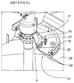
- FIG. 3 shows the flotation apparatus shown in FIG. 1 in partly cut state
- FIG. 4 shows detail A of FIG. 3 in greater scale
- FIG. 5 shows the flotation apparatus shown in FIG. 1 from one side
- FIG. 6 shows the flotation apparatus shown in FIG. 1 as cut along line B-B in FIG. 5 ,
- FIG. 7 shows an agitating means, which can be used in the flotation apparatus shown in FIG. 1 ,
- FIG. 8 shows the agitating means shown in FIG. 7 as seen from one side
- FIG. 9 shows the agitating means shown in FIG. 7 as partly cut along line C-C in FIG. 8 .
- FIG. 10 shows the agitating means of the flotation apparatus shown in FIG. 1 .
- FIG. 11 shows the agitating means shown in FIG. 10 as seen from one side
- FIG. 12 shows the agitating means shown in FIG. 10 as partly cut along line D-D in FIG. 11 .
- FIG. 13 shows the connecting piece of the flotation apparatus shown in FIG. 1 in exploded view.
- a flotation apparatus 1 such as a froth flotation apparatus
- the method comprises providing a flotation vessel 2 and a cover 3 for closing an upwards open opening 4 of the flotation vessel 3 , wherein the cover 3 and the flotation vessel 2 limiting a vessel space 5 for receiving fluid (not shown in the figures).
- the method comprises providing an agitating means 6 having a rotatable shaft 7 .
- the method comprises arranging the rotatable shaft 7 of the agitating means 6 to extend through a first aperture 8 in the cover 3 .
- the method comprises supporting the rotatable shaft 7 at a bearing housing 9 outside the vessel space 5 .
- the method comprises providing a connection arrangement 10 that surrounds the rotatable shaft 7 between the bearing housing 9 and the cover 3 .
- connection arrangement 10 is to at least partly seal the rotatable shaft 7 from the surrounding environment between the bearing housing 9 and the cover 3 .
- the method may comprise by attaching the connection arrangement 10 to the bearing housing 9 to simplify the construction.
- the method may comprise attaching the connection arrangement 10 to the cover 3 to simplify the construction.
- the method may comprise attaching the connection arrangement 10 both to the bearing housing 9 and to the cover 3 so that the connection arrangement 10 hermetically sealing the rotatable shaft 7 between the bearing housing 9 and the cover 3 to simplify the construction.
- the method may comprise providing a connection arrangement 10 comprising a connection piece 11 surrounding the rotatable shaft 7 between the bearing housing 9 and the cover 3 .
- connection piece 11 may comprise at an end facing the bearing housing 9 a first opening 12 for the rotatable shaft 7 , and at an end facing the vessel space 5 of the vessel space 5 a second opening 13 for the rotatable shaft 7 .
- connection piece 11 may comprise a hollow truncated cone 14 surrounding the rotatable shaft 7 between the bearing housing 9 and the cover 3 the connection piece 11 , so that the hollow truncated cone 14 tapers towards the bearing housing 9 , so that the connection piece 11 having at the end facing the bearing housing 9 the first opening 12 for the rotatable shaft 7 , and so that the connection piece 11 having at the end facing the vessel space 5 of the flotation vessel 1 the second opening 13 for the rotatable shaft 7 .
- connection piece 11 may, as shown in FIG. 13 , comprise at least two connection piece parts 15 releasable connected to each other so that division planes 16 between said least two connection piece parts 15 extending between the first opening 12 and the second opening 13 so that the connection piece 11 can be removed from the surrounding state without moving the connection piece 11 via an end of the rotatable shaft 7 .
- connection piece 11 that may be provided can comprise a first flange 17 at the end facing the bearing housing 9 , wherein the method comprises releasable fastening the connection piece 11 to the bearing housing 9 by using the first flange 17 . This facilitates removal and mounting of the connection piece 11 .
- connection arrangement 10 may comprise a bellow arrangement 18 surrounding the rotatable shaft 7 between the bearing housing 9 and the cover 3 to provide for relative movement between the bearing housing 9 and the cover 3 .
- the connection arrangement 10 may be composed of a bellow arrangement 18 .
- connection piece 11 of any of the embodiments as described earlier is provided, the possible bellow arrangement 18 can be arranged between the cover 3 and the connection piece 11 , and the connection piece 11 is correspondingly between the bearing housing 9 and the bellow arrangement 18 .
- the optional bellow arrangement 18 can be attached to the connection piece 11 by means of a second flange 19 , and the bellow arrangement 18 can be attached to the cover 3 by means of a third flange 20 to provide for tight, hermetically sealing.
- the second flange 19 can be connected with the third flange 20 by means of a travel limiter 21 to limit the travel of the second flange 19 with respect to the third flange 20 , i.e. to prevent excess movement between the second flange 19 and the third flange 20 .
- the method may comprise providing a gasket (not shown in the figures) to surround the rotatable shaft 7 between the bearing housing 9 and the rotatable shaft 7 to provide for additional sealing, prevents possible toxic gases from escaping.
- a gasket (not shown in the figures) to surround the rotatable shaft 7 between the bearing housing 9 and the rotatable shaft 7 to provide for additional sealing, prevents possible toxic gases from escaping.
- the method may comprise connecting a gas feeding means 23 in fluid connection with the vessel space 5 .
- Gas from a gas feeding means 23 is normally needed in a flotation process.
- the flotation vessel 2 that is provided comprises a vessel space 5 comprising an inner bottom 24 , and in such case the method comprises preferably, but not necessarily, connecting the gas feeding means 23 in fluid connection with the vessel space 5 at a gas outlet 25 that is located closer to the inner bottom 24 of the vessel space 5 than to the upwards open opening 4 of the vessel space 5 .
- a gas feeding means 23 comprising a gas feeding duct 26 in the rotatable shaft 7 of the agitating means 6 , outside the vessel space 5 a gas inlet 27 for feeding gas into the gas feeding duct 26 , and inside the vessel space 5 a gas outlet 25 for feeding gas from the gas feeding duct 26 into the vessel space 5 .
- the bearing housing 9 may being arranged between the gas inlet 27 and the cover 3 to enable proper sealing of the rotatable shaft 7 between the cover 3 and the bearing housing 9 .
- the method may comprise supporting the rotatable shaft 7 additionally at an additional bearing housing 28 so that the gas inlet 27 is situated between the bearing housing 9 and the additional bearing housing 28 to provide for stable supporting of the rotatable shaft 7 especially if rotatable shaft 7 is supported only outside the vessel space 5 .
- the vessel space 5 of the flotation vessel 2 that is provided may be a vertical cylindrical vessel space 5 having a circular inner bottom 24 , and having an upwards open opening 4 in the form of a circular upwards open opening.
- the rotatable shaft 7 can be arranged to extend vertically at a vertical center axis E of the vertical cylindrical vessel space 5 .
- the agitating means 6 may comprise a rotor 33 that is attached to the rotatable shaft 7 , preferably to a distal end of the rotatable shaft 7 .
- the rotor 33 may be at least partly surrounded by a stator 34 .
- the method may comprise fastening the stator 34 being fastened to the flotation vessel 2 in the vessel space 5 , preferably to the circular inner bottom 24 of the vertical cylindrical inner space.
- the method may comprise providing a flotation vessel 2 , where the cover 3 is composed of a first cover part 29 and a second cover part 30 that is releasable attached to the first cover part 29 , so that the first cover part 29 comprises a second aperture 31 that is covered by the second cover part 30 , and so that the first aperture 8 is in the second cover part 30 .
- the method comprises fastening the connection arrangement 10 to the second cover part 30 .
- the method comprises providing the second aperture 31 so that it is circular and having a diameter that is larger than an outer diameter of a rotor 33 attached to the rotatable shaft 7 .
- the method comprises providing a sealing (not shown in the figures) between the first cover part 29 and the second cover part 30 .
- the method may comprise providing the agitating means 6 with a motor means 32 for rotating the rotatable shaft 7 .
- flotation apparatus 1 such as a froth flotation apparatus and some embodiments and variants thereof will be described in greater detail.
- the flotation apparatus 1 comprises a flotation vessel 2 and a cover 3 for closing an upwards open opening 4 of the flotation vessel.
- the cover 3 and the flotation vessel 2 limits a vessel space 5 for receiving fluid.
- the flotation apparatus 1 comprises an agitating means 6 having a rotatable axis extending through a first aperture 8 in the cover 3 .
- the rotatable shaft 7 is rotatable supported at a bearing housing 9 outside the vessel space 5 .
- the flotation apparatus 1 comprises a connection arrangement 10 surrounding the rotatable shaft 7 between the bearing housing 9 and the cover 3 .
- a purpose of the sealing arrangement is to at least partly seal the rotatable shaft 7 from the surrounding environment between the bearing housing 9 and the cover 3 .
- connection arrangement 10 may be attached to the bearing housing 9 , which results in a simplified construction.
- connection arrangement 10 may be attached to the cover 3 , which results in a simplified construction.
- connection arrangement 10 may be attached to the bearing housing 9 and to the cover 3 so that the connection arrangement 10 hermetically sealing the rotatable shaft 7 , which results in a simplified construction.
- connection arrangement 10 may comprise a connection piece 11 surrounding the rotatable shaft 7 between the bearing housing 9 and the cover 3 .
- the connection piece 11 has preferably at the end facing the bearing housing 9 a first opening 12 for the rotatable shaft 7 , and at the end facing the vessel space 5 of the flotation vessel 2 a second opening 13 for the rotatable shaft 7 .
- connection piece 11 comprises preferably, but not necessarily, a hollow truncated cone 14 so that the connection piece 11 tapers towards the bearing housing 9 , so that the connection piece 11 having at the end facing the bearing housing 9 the first opening 12 for the rotatable shaft 7 , and so that the connection piece 11 having at the end facing the vessel space 5 of the flotation vessel 2 the second opening 13 for the rotatable shaft 7 .
- connection arrangement 10 comprises a connection piece 11 as described earlier having at the end facing the bearing housing 9 a first opening 12 for the rotatable shaft 7 , and having at the end facing the vessel space 5 of the flotation vessel 2 a second opening 13 for the rotatable shaft 7 , as described, the connection piece 11 comprises preferably, but not necessarily, at least two connection piece parts 15 releasable connected to each other, so that division planes 16 between said least two connection piece parts 15 extending between the first opening 12 and the second opening 13 . This provides for removing and mounting of the connection piece 11 from the surrounding state without moving the connection piece 11 via an end of the rotatable shaft 7 .
- connection piece 11 may comprise a first flange 17 at the end facing the bearing housing 9 for releasable fastening the connection piece 11 to the bearing housing 9 to facilitate removal and mounting of the connection piece 11
- connection arrangement 10 may comprise a bellow arrangement 18 surrounding the rotatable shaft 7 between the bearing housing 9 and the cover 3 to provide for relative movement between the bearing housing 9 and the cover 3 .
- the bellow arrangement 18 may substitute a connection piece 11 .
- connection arrangement 10 comprise a bellow arrangement 18 surrounding the rotatable shaft 7 between the bearing housing 9 and the cover 3
- the bellow arrangement 18 may be arranged between the cover 3 and the connection piece 11
- the connection piece 11 may be arranged between the bearing housing 9 and the bellow arrangement 18 as in the embodiments shown in the figures.
- the connection arrangement 10 comprises both a bellow arrangement 18 and a connection piece 11
- the bellow arrangement 18 can be made small.
- the bellow arrangement 18 is attached to the connection piece 11 by means of a second flange 19
- the bellow arrangement 18 is attached to the cover 3 by means of a third flange 20 .
- the second flange 19 is connected with the third flange 20 by means of a travel limiter 21 configured to limit the travel of the second flange 19 with respect to the third flange 20 to prevent excess movement of the of the second flange 19 with respect to the third flange 20 .
- the flotation apparatus 1 may comprise a gasket (not shown in the figures) surrounding the rotatable shaft 7 between the bearing housing 9 and the rotatable shaft 7 to provide for additional sealing and to prevent possible toxic gases from escaping from between the bearing housing 9 and the rotatable shaft 7 .
- the flotation apparatus 1 may comprise gas feeding means 23 for feeding gas needed for the flotation process into the vessel space 5 .
- the gas feeding means 23 may be configured to feed gas into the vessel space 5 at a gas outlet 25 that is located closer to the inner bottom 24 of the vessel space 5 than to the cover 3 .
- the gas feeding means 23 may comprise a gas feeding duct 26 in the rotatable shaft 7 of the agitating means 6 , outside the vessel space 5 a gas inlet 27 for feeding gas into the gas feeding duct 26 , and inside the vessel space 5 a gas outlet 25 for feeding gas from the gas feeding duct 26 into the vessel space 5 .
- the bearing housing 9 may be arranged between the gas inlet 27 and the cover 3 to provide for proper sealing of the rotatable shaft 7 between the cover 3 and the bearing housing 9 .
- the vessel space 5 of the flotation apparatus 1 may, as shown in the figures, be a vertical cylindrical vessel space 5 having a circular inner bottom 24 , and having a circular open top.
- the rotatable shaft 7 may extend vertically at a vertical center axis E of the vertical cylindrical vessel space 5 , as shown in the figures.
- the agitating means 6 of the flotation apparatus 1 may, as shown in the figures, comprise a rotor 33 that is attached to the rotatable shaft 7 .
- the rotor 33 may be at least partly surrounded by a stator 34 .
- the stator 34 may be fastened to the flotation vessel 2 in the vessel space 5 .
- the cover 3 of the flotation apparatus 1 may, as shown in the figures, be composed of a first cover part 29 and a second cover part 30 that is releasable attached to the first cover part 29 .
- the first cover part 29 comprises a second aperture 31 that is covered by the second cover part 30 , and the first aperture 8 is in the second cover part 30 .
- the connection arrangement 10 is fastened to the second cover part 30 .
- the second aperture 31 is circular, has a diameter that is larger than an outer diameter of a rotor 33 attached to the rotatable shaft 7 and a sealing is provided between the first cover part 29 and the second cover part 30 .
- the agitating means 6 of the flotation apparatus 1 may comprise a motor means 32 for rotating the rotatable shaft 7 .
- the invention relates also to a system for flotation, comprising a flotation apparatus 1 according to embodiment describe herein.
- connection arrangement 10 for use in a method according to any embodiment described or in a flotation apparatus 1 according to any embodiment described.
- the connection arrangement comprises a connection piece 11 having at a first end a first opening 12 for the rotatable shaft 7 and having at a second end a second opening 13 for the rotatable shaft 7 .
- the connection piece 11 comprises at least two connection piece parts 15 releasable connected to each other. Division planes 16 between said least two connection piece parts 15 extends between the first opening 12 and the second opening 13 .
- connection piece 11 comprises a first flange 17 at the first end for releasable fastening the connection piece 11 to the bearing housing 9 , and a second flange 19 at the second end housing for releasable fastening the connection piece 11 to a bellow arrangement 18 .
- the invention relates also to the use of the method according to any embodiment described herein and to the use of the flotation apparatus according to any embodiment described herein in a flotation process of a slurry having a density that is between 1100 and 1600 kg/m 3 , preferably between 1200 and 1400 kg/m 3 .
- the invention relates also to the use of the method according to any embodiment described herein and to the use of the flotation apparatus according to any embodiment described herein for creating a pressure difference.
- the invention relates also to the use of the method according to any embodiment described herein and to the use of the flotation apparatus according to any embodiment described herein for separation of minerals.
Landscapes
- Life Sciences & Earth Sciences (AREA)
- Engineering & Computer Science (AREA)
- Biotechnology (AREA)
- Accessories For Mixers (AREA)
- Consolidation Of Soil By Introduction Of Solidifying Substances Into Soil (AREA)
Abstract
Description
Claims (15)
Applications Claiming Priority (3)
| Application Number | Priority Date | Filing Date | Title |
|---|---|---|---|
| FI20155965 | 2015-12-18 | ||
| FI20155965A FI126689B (en) | 2015-12-18 | 2015-12-18 | PROCEDURE FOR CONSTRUCTING A FLOTING DEVICE, FLOTING DEVICE, FLOTING PROCEDURE AND SYSTEM, AND USE |
| PCT/FI2016/050873 WO2017103332A2 (en) | 2015-12-18 | 2016-12-15 | Method for constructing a flotation apparatus, flotation apparatus, method and system for flotation and use |
Publications (2)
| Publication Number | Publication Date |
|---|---|
| US20190126292A1 US20190126292A1 (en) | 2019-05-02 |
| US10507472B2 true US10507472B2 (en) | 2019-12-17 |
Family
ID=57680283
Family Applications (1)
| Application Number | Title | Priority Date | Filing Date |
|---|---|---|---|
| US16/061,060 Active US10507472B2 (en) | 2015-12-18 | 2016-12-15 | Method for constructing a flotation apparatus, flotation apparatus, method and system for flotation and use |
Country Status (6)
| Country | Link |
|---|---|
| US (1) | US10507472B2 (en) |
| CL (1) | CL2018001554A1 (en) |
| FI (1) | FI126689B (en) |
| MX (1) | MX2018007131A (en) |
| PE (1) | PE20181102A1 (en) |
| WO (1) | WO2017103332A2 (en) |
Families Citing this family (1)
| Publication number | Priority date | Publication date | Assignee | Title |
|---|---|---|---|---|
| CN115634780B (en) * | 2022-11-11 | 2024-07-05 | 昆明理工大学 | Laboratory closed type inflatable flotation equipment and flotation method thereof |
Citations (15)
| Publication number | Priority date | Publication date | Assignee | Title |
|---|---|---|---|---|
| US2134410A (en) * | 1936-09-28 | 1938-10-25 | Kraut Max | Flotation apparatus |
| US2269583A (en) * | 1939-02-03 | 1942-01-13 | Frank A Dromgold | Material separation device |
| US2375282A (en) * | 1941-12-20 | 1945-05-08 | Dorr Co | Purification of liquids |
| US2713477A (en) * | 1952-04-07 | 1955-07-19 | Mining Process & Patent Co | Dual aerating apparatus and method |
| US3599990A (en) * | 1969-10-13 | 1971-08-17 | Sealol | Shaft seal |
| US3722679A (en) * | 1970-09-24 | 1973-03-27 | L Logue | Method and means for froth flotation concentration utilizing an aerator having a venturi passage |
| US4028229A (en) * | 1974-03-22 | 1977-06-07 | National Research Development Corporation | Froth flotation |
| EP0224762A2 (en) | 1985-11-27 | 1987-06-10 | Insinööritoimisto LISOP OY | Reaction cell |
| US5188377A (en) * | 1989-12-05 | 1993-02-23 | Nuraseal Company, Limited | Externally-mounted, stationary-design, self-aligning rotary face seal |
| US5281033A (en) * | 1990-10-09 | 1994-01-25 | Ide Russell D | Housed bearing assembly with sealed roller |
| US20030030157A1 (en) * | 2001-08-10 | 2003-02-13 | Aeromix Systems, Inc. | Horizontal surface aerator |
| US20040130042A1 (en) | 2003-01-06 | 2004-07-08 | Spx Corporation | Agitator and drive apparatus and method |
| DE69831756T2 (en) | 1997-12-17 | 2009-09-24 | A.W. Chesterton Co., Stoneham | SEALING SEAL WITH DIVIDED RINGS |
| WO2013054610A1 (en) * | 2011-10-11 | 2013-04-18 | イーグル工業株式会社 | Divided mechanical seal device |
| WO2013067343A1 (en) * | 2011-11-04 | 2013-05-10 | Flsmidth A/S | Flotation cell vortex stabilizer |
-
2015
- 2015-12-18 FI FI20155965A patent/FI126689B/en active IP Right Grant
-
2016
- 2016-12-15 PE PE2018001121A patent/PE20181102A1/en unknown
- 2016-12-15 WO PCT/FI2016/050873 patent/WO2017103332A2/en active Application Filing
- 2016-12-15 US US16/061,060 patent/US10507472B2/en active Active
- 2016-12-15 MX MX2018007131A patent/MX2018007131A/en unknown
-
2018
- 2018-06-12 CL CL2018001554A patent/CL2018001554A1/en unknown
Patent Citations (15)
| Publication number | Priority date | Publication date | Assignee | Title |
|---|---|---|---|---|
| US2134410A (en) * | 1936-09-28 | 1938-10-25 | Kraut Max | Flotation apparatus |
| US2269583A (en) * | 1939-02-03 | 1942-01-13 | Frank A Dromgold | Material separation device |
| US2375282A (en) * | 1941-12-20 | 1945-05-08 | Dorr Co | Purification of liquids |
| US2713477A (en) * | 1952-04-07 | 1955-07-19 | Mining Process & Patent Co | Dual aerating apparatus and method |
| US3599990A (en) * | 1969-10-13 | 1971-08-17 | Sealol | Shaft seal |
| US3722679A (en) * | 1970-09-24 | 1973-03-27 | L Logue | Method and means for froth flotation concentration utilizing an aerator having a venturi passage |
| US4028229A (en) * | 1974-03-22 | 1977-06-07 | National Research Development Corporation | Froth flotation |
| EP0224762A2 (en) | 1985-11-27 | 1987-06-10 | Insinööritoimisto LISOP OY | Reaction cell |
| US5188377A (en) * | 1989-12-05 | 1993-02-23 | Nuraseal Company, Limited | Externally-mounted, stationary-design, self-aligning rotary face seal |
| US5281033A (en) * | 1990-10-09 | 1994-01-25 | Ide Russell D | Housed bearing assembly with sealed roller |
| DE69831756T2 (en) | 1997-12-17 | 2009-09-24 | A.W. Chesterton Co., Stoneham | SEALING SEAL WITH DIVIDED RINGS |
| US20030030157A1 (en) * | 2001-08-10 | 2003-02-13 | Aeromix Systems, Inc. | Horizontal surface aerator |
| US20040130042A1 (en) | 2003-01-06 | 2004-07-08 | Spx Corporation | Agitator and drive apparatus and method |
| WO2013054610A1 (en) * | 2011-10-11 | 2013-04-18 | イーグル工業株式会社 | Divided mechanical seal device |
| WO2013067343A1 (en) * | 2011-11-04 | 2013-05-10 | Flsmidth A/S | Flotation cell vortex stabilizer |
Non-Patent Citations (3)
| Title |
|---|
| Finnish Search Report issued by the Finnish Patent and Registration Office in relation to Finnish Application No. 20155965 dated Jun. 16, 2016 (1 page). |
| International Search Report issued by the European Patent Office acting as the International Searching Authority in relation to International Patent Application No. PCT/FI2016/050873 dated Dec. 15, 2017 (6 pages). |
| Written Opinion of the International Searching Authority issued by the European Patent Office acting as the International Searching Authority in relation to International Patent Application No. PCT/FI2016/050873 dated Dec. 15, 2017 (10 pages). |
Also Published As
| Publication number | Publication date |
|---|---|
| WO2017103332A3 (en) | 2018-01-25 |
| FI20155965A7 (en) | 2017-04-13 |
| CL2018001554A1 (en) | 2018-07-20 |
| PE20181102A1 (en) | 2018-07-12 |
| WO2017103332A2 (en) | 2017-06-22 |
| US20190126292A1 (en) | 2019-05-02 |
| FI126689B (en) | 2017-04-13 |
| MX2018007131A (en) | 2018-11-09 |
Similar Documents
| Publication | Publication Date | Title |
|---|---|---|
| EP1707762A3 (en) | Steam turbine exhaust system | |
| ES2965723T3 (en) | Separator | |
| US10507472B2 (en) | Method for constructing a flotation apparatus, flotation apparatus, method and system for flotation and use | |
| WO2010096410A3 (en) | System and method for gas reaction | |
| CN113164984B (en) | Replaceable breakaway insert | |
| AU2013242071B2 (en) | Separator arrangement | |
| WO2008085196A3 (en) | Fluidic sealing system for a wet drum magnetic separator | |
| WO2002053292A3 (en) | Centrifuge comprising a blood bag system with an upper and lower outlet | |
| MY159711A (en) | Capsule and system for preparing a beverage by centrifugation in a beverage production device | |
| AU2014203537A1 (en) | Ship’s propulsion unit | |
| MX2018015376A (en) | Anaerobic reactor. | |
| CR20200309A (en) | Composite cover plate for the wall mounting of modular electrical apparatuses | |
| CN113164977A (en) | Centrifugal separator and method for eliminating airlock in a centrifugal separator | |
| MX2018011545A (en) | Hydrocarbon-water separator. | |
| RU2012127623A (en) | REACTOR INCLUDING A ROTOR | |
| WO2018134758A3 (en) | Liquid separator with improved filter service access and dedicated filter service replacement tool | |
| DE59813621D1 (en) | BIOGAS PLANT | |
| WO2017164747A8 (en) | Hydrocarbon-water separator | |
| KR102566691B1 (en) | centrifugal | |
| EP3381840B1 (en) | Dew-condensation preventing device in discharge chute and powder and grain supplying apparatus using same | |
| US10213720B2 (en) | Liquid separator | |
| FI69257C (en) | ANORDNING FOER MATNING AV PULVERISERAT MATERIAL | |
| AU2015245635B2 (en) | Shaft feed-through | |
| US4740128A (en) | Apparatus for discharging a reaction vessel | |
| KR101574179B1 (en) | Centrifugal dehydrator of having improved watertightness |
Legal Events
| Date | Code | Title | Description |
|---|---|---|---|
| FEPP | Fee payment procedure |
Free format text: ENTITY STATUS SET TO UNDISCOUNTED (ORIGINAL EVENT CODE: BIG.); ENTITY STATUS OF PATENT OWNER: LARGE ENTITY |
|
| AS | Assignment |
Owner name: OUTOTEC (FINLAND) OY, FINLAND Free format text: ASSIGNMENT OF ASSIGNORS INTEREST;ASSIGNORS:PELTOLA, ALEKSI;GRAU, RODRIGO;SIGNING DATES FROM 20180531 TO 20180626;REEL/FRAME:046235/0516 |
|
| STPP | Information on status: patent application and granting procedure in general |
Free format text: NOTICE OF ALLOWANCE MAILED -- APPLICATION RECEIVED IN OFFICE OF PUBLICATIONS |
|
| STPP | Information on status: patent application and granting procedure in general |
Free format text: PUBLICATIONS -- ISSUE FEE PAYMENT RECEIVED |
|
| STPP | Information on status: patent application and granting procedure in general |
Free format text: PUBLICATIONS -- ISSUE FEE PAYMENT VERIFIED |
|
| STCF | Information on status: patent grant |
Free format text: PATENTED CASE |
|
| AS | Assignment |
Owner name: METSO MINERALS OY, FINLAND Free format text: MERGER;ASSIGNOR:OUTOTEC (FINLAND) OY;REEL/FRAME:061685/0481 Effective date: 20210101 Owner name: METSO OUTOTEC FINLAND OY, FINLAND Free format text: CHANGE OF NAME;ASSIGNOR:METSO MINERALS OY;REEL/FRAME:061685/0552 Effective date: 20210101 |
|
| MAFP | Maintenance fee payment |
Free format text: PAYMENT OF MAINTENANCE FEE, 4TH YEAR, LARGE ENTITY (ORIGINAL EVENT CODE: M1551); ENTITY STATUS OF PATENT OWNER: LARGE ENTITY Year of fee payment: 4 |
|
| AS | Assignment |
Owner name: METSO FINLAND OY, FINLAND Free format text: CHANGE OF NAME;ASSIGNOR:METSO OUTOTEC FINLAND OY;REEL/FRAME:070731/0681 Effective date: 20230901 |