US10486441B2 - Printing apparatus, inspection apparatus, and method of controlling the inspection apparatus in which a fixing unit fixes a relative position between a detection surface of a reading unit and a print medium - Google Patents
Printing apparatus, inspection apparatus, and method of controlling the inspection apparatus in which a fixing unit fixes a relative position between a detection surface of a reading unit and a print medium Download PDFInfo
- Publication number
- US10486441B2 US10486441B2 US15/891,848 US201815891848A US10486441B2 US 10486441 B2 US10486441 B2 US 10486441B2 US 201815891848 A US201815891848 A US 201815891848A US 10486441 B2 US10486441 B2 US 10486441B2
- Authority
- US
- United States
- Prior art keywords
- unit
- print medium
- image
- conveyance
- reading
- Prior art date
- Legal status (The legal status is an assumption and is not a legal conclusion. Google has not performed a legal analysis and makes no representation as to the accuracy of the status listed.)
- Expired - Fee Related
Links
- 238000007639 printing Methods 0.000 title claims abstract description 43
- 238000001514 detection method Methods 0.000 title claims abstract description 40
- 238000007689 inspection Methods 0.000 title claims description 55
- 238000000034 method Methods 0.000 title claims description 33
- 238000012546 transfer Methods 0.000 claims description 125
- 230000007246 mechanism Effects 0.000 claims description 39
- 230000003028 elevating effect Effects 0.000 claims description 28
- 238000003825 pressing Methods 0.000 claims description 9
- 230000008859 change Effects 0.000 claims description 7
- 238000011144 upstream manufacturing Methods 0.000 claims description 7
- 239000000976 ink Substances 0.000 description 115
- 238000012545 processing Methods 0.000 description 42
- 239000007788 liquid Substances 0.000 description 40
- 238000011084 recovery Methods 0.000 description 24
- 239000000463 material Substances 0.000 description 22
- 230000002093 peripheral effect Effects 0.000 description 22
- 239000010410 layer Substances 0.000 description 19
- 238000004140 cleaning Methods 0.000 description 13
- 238000003860 storage Methods 0.000 description 13
- 238000010438 heat treatment Methods 0.000 description 12
- 238000010521 absorption reaction Methods 0.000 description 10
- 229920005989 resin Polymers 0.000 description 9
- 239000011347 resin Substances 0.000 description 9
- 229910019250 POS3 Inorganic materials 0.000 description 8
- 238000004891 communication Methods 0.000 description 8
- 238000001816 cooling Methods 0.000 description 8
- 238000012805 post-processing Methods 0.000 description 8
- 230000008569 process Effects 0.000 description 8
- 238000004040 coloring Methods 0.000 description 7
- 229920001971 elastomer Polymers 0.000 description 7
- 239000000758 substrate Substances 0.000 description 7
- 239000002344 surface layer Substances 0.000 description 7
- 208000019300 CLIPPERS Diseases 0.000 description 6
- 230000015572 biosynthetic process Effects 0.000 description 6
- 208000021930 chronic lymphocytic inflammation with pontine perivascular enhancement responsive to steroids Diseases 0.000 description 6
- 230000006870 function Effects 0.000 description 6
- 239000005060 rubber Substances 0.000 description 6
- 238000011282 treatment Methods 0.000 description 6
- 239000011148 porous material Substances 0.000 description 4
- 230000002441 reversible effect Effects 0.000 description 4
- 238000006748 scratching Methods 0.000 description 4
- 230000002393 scratching effect Effects 0.000 description 4
- 229920002379 silicone rubber Polymers 0.000 description 4
- 229920000459 Nitrile rubber Polymers 0.000 description 3
- 238000009835 boiling Methods 0.000 description 3
- 239000000919 ceramic Substances 0.000 description 3
- 239000011248 coating agent Substances 0.000 description 3
- 238000000576 coating method Methods 0.000 description 3
- 239000000470 constituent Substances 0.000 description 3
- 238000010586 diagram Methods 0.000 description 3
- 230000001965 increasing effect Effects 0.000 description 3
- 238000002156 mixing Methods 0.000 description 3
- 239000004065 semiconductor Substances 0.000 description 3
- 239000004945 silicone rubber Substances 0.000 description 3
- 239000007787 solid Substances 0.000 description 3
- 238000004381 surface treatment Methods 0.000 description 3
- XLYOFNOQVPJJNP-UHFFFAOYSA-N water Substances O XLYOFNOQVPJJNP-UHFFFAOYSA-N 0.000 description 3
- IJGRMHOSHXDMSA-UHFFFAOYSA-N Atomic nitrogen Chemical compound N#N IJGRMHOSHXDMSA-UHFFFAOYSA-N 0.000 description 2
- KAKZBPTYRLMSJV-UHFFFAOYSA-N Butadiene Chemical compound C=CC=C KAKZBPTYRLMSJV-UHFFFAOYSA-N 0.000 description 2
- PPBRXRYQALVLMV-UHFFFAOYSA-N Styrene Chemical compound C=CC1=CC=CC=C1 PPBRXRYQALVLMV-UHFFFAOYSA-N 0.000 description 2
- 229920006311 Urethane elastomer Polymers 0.000 description 2
- 230000006835 compression Effects 0.000 description 2
- 238000007906 compression Methods 0.000 description 2
- 230000007423 decrease Effects 0.000 description 2
- 230000003247 decreasing effect Effects 0.000 description 2
- 238000007599 discharging Methods 0.000 description 2
- 238000006073 displacement reaction Methods 0.000 description 2
- 229920005560 fluorosilicone rubber Polymers 0.000 description 2
- 238000012423 maintenance Methods 0.000 description 2
- 238000004519 manufacturing process Methods 0.000 description 2
- 239000000155 melt Substances 0.000 description 2
- 229920001084 poly(chloroprene) Polymers 0.000 description 2
- 239000004925 Acrylic resin Substances 0.000 description 1
- 229920000178 Acrylic resin Polymers 0.000 description 1
- 229920000181 Ethylene propylene rubber Polymers 0.000 description 1
- KRHYYFGTRYWZRS-UHFFFAOYSA-M Fluoride anion Chemical compound [F-] KRHYYFGTRYWZRS-UHFFFAOYSA-M 0.000 description 1
- YCKRFDGAMUMZLT-UHFFFAOYSA-N Fluorine atom Chemical compound [F] YCKRFDGAMUMZLT-UHFFFAOYSA-N 0.000 description 1
- 244000043261 Hevea brasiliensis Species 0.000 description 1
- 101000911772 Homo sapiens Hsc70-interacting protein Proteins 0.000 description 1
- 101001139126 Homo sapiens Krueppel-like factor 6 Proteins 0.000 description 1
- CBENFWSGALASAD-UHFFFAOYSA-N Ozone Chemical compound [O-][O+]=O CBENFWSGALASAD-UHFFFAOYSA-N 0.000 description 1
- 239000005062 Polybutadiene Substances 0.000 description 1
- BLRPTPMANUNPDV-UHFFFAOYSA-N Silane Chemical compound [SiH4] BLRPTPMANUNPDV-UHFFFAOYSA-N 0.000 description 1
- XUIMIQQOPSSXEZ-UHFFFAOYSA-N Silicon Chemical compound [Si] XUIMIQQOPSSXEZ-UHFFFAOYSA-N 0.000 description 1
- NIXOWILDQLNWCW-UHFFFAOYSA-N acrylic acid group Chemical group C(C=C)(=O)O NIXOWILDQLNWCW-UHFFFAOYSA-N 0.000 description 1
- 229920000800 acrylic rubber Polymers 0.000 description 1
- 239000000853 adhesive Substances 0.000 description 1
- 230000001070 adhesive effect Effects 0.000 description 1
- 239000002390 adhesive tape Substances 0.000 description 1
- 230000008901 benefit Effects 0.000 description 1
- 230000033228 biological regulation Effects 0.000 description 1
- 230000005540 biological transmission Effects 0.000 description 1
- 230000000740 bleeding effect Effects 0.000 description 1
- 238000007664 blowing Methods 0.000 description 1
- 239000003795 chemical substances by application Substances 0.000 description 1
- 239000000701 coagulant Substances 0.000 description 1
- 230000001112 coagulating effect Effects 0.000 description 1
- 230000015271 coagulation Effects 0.000 description 1
- 238000005345 coagulation Methods 0.000 description 1
- 239000003086 colorant Substances 0.000 description 1
- 230000000295 complement effect Effects 0.000 description 1
- 229920001577 copolymer Polymers 0.000 description 1
- 238000003851 corona treatment Methods 0.000 description 1
- 238000012937 correction Methods 0.000 description 1
- 230000008878 coupling Effects 0.000 description 1
- 238000010168 coupling process Methods 0.000 description 1
- 238000005859 coupling reaction Methods 0.000 description 1
- 238000005520 cutting process Methods 0.000 description 1
- 238000007607 die coating method Methods 0.000 description 1
- 239000000428 dust Substances 0.000 description 1
- 239000000806 elastomer Substances 0.000 description 1
- 230000005611 electricity Effects 0.000 description 1
- HQQADJVZYDDRJT-UHFFFAOYSA-N ethene;prop-1-ene Chemical group C=C.CC=C HQQADJVZYDDRJT-UHFFFAOYSA-N 0.000 description 1
- 239000004744 fabric Substances 0.000 description 1
- 239000000945 filler Substances 0.000 description 1
- 239000010419 fine particle Substances 0.000 description 1
- 239000012530 fluid Substances 0.000 description 1
- 229910052731 fluorine Inorganic materials 0.000 description 1
- 239000011737 fluorine Substances 0.000 description 1
- 239000004088 foaming agent Substances 0.000 description 1
- 239000011521 glass Substances 0.000 description 1
- 238000003384 imaging method Methods 0.000 description 1
- 230000010365 information processing Effects 0.000 description 1
- 229920003049 isoprene rubber Polymers 0.000 description 1
- 238000003475 lamination Methods 0.000 description 1
- 239000010985 leather Substances 0.000 description 1
- QSHDDOUJBYECFT-UHFFFAOYSA-N mercury Chemical compound [Hg] QSHDDOUJBYECFT-UHFFFAOYSA-N 0.000 description 1
- 229910052753 mercury Inorganic materials 0.000 description 1
- 229910052751 metal Inorganic materials 0.000 description 1
- 239000002184 metal Substances 0.000 description 1
- 229910021645 metal ion Inorganic materials 0.000 description 1
- 229910044991 metal oxide Inorganic materials 0.000 description 1
- 150000004706 metal oxides Chemical class 0.000 description 1
- 238000012986 modification Methods 0.000 description 1
- 230000004048 modification Effects 0.000 description 1
- 229920003052 natural elastomer Polymers 0.000 description 1
- 229920001194 natural rubber Polymers 0.000 description 1
- 229910052757 nitrogen Inorganic materials 0.000 description 1
- 230000003287 optical effect Effects 0.000 description 1
- 150000007524 organic acids Chemical class 0.000 description 1
- 239000003960 organic solvent Substances 0.000 description 1
- 150000003961 organosilicon compounds Chemical class 0.000 description 1
- 230000000737 periodic effect Effects 0.000 description 1
- 125000001997 phenyl group Chemical group [H]C1=C([H])C([H])=C(*)C([H])=C1[H] 0.000 description 1
- XJWOWXZSFTXJEX-UHFFFAOYSA-N phenylsilicon Chemical compound [Si]C1=CC=CC=C1 XJWOWXZSFTXJEX-UHFFFAOYSA-N 0.000 description 1
- 238000009832 plasma treatment Methods 0.000 description 1
- 239000002985 plastic film Substances 0.000 description 1
- 229920006255 plastic film Polymers 0.000 description 1
- 238000005498 polishing Methods 0.000 description 1
- 229920000058 polyacrylate Polymers 0.000 description 1
- 229920002857 polybutadiene Polymers 0.000 description 1
- 238000007781 pre-processing Methods 0.000 description 1
- 230000001737 promoting effect Effects 0.000 description 1
- 230000004044 response Effects 0.000 description 1
- 150000003839 salts Chemical class 0.000 description 1
- 238000001878 scanning electron micrograph Methods 0.000 description 1
- 238000007790 scraping Methods 0.000 description 1
- 229910000077 silane Inorganic materials 0.000 description 1
- 229910052710 silicon Inorganic materials 0.000 description 1
- 239000010703 silicon Substances 0.000 description 1
- 229920002050 silicone resin Polymers 0.000 description 1
- 239000002356 single layer Substances 0.000 description 1
- 239000002904 solvent Substances 0.000 description 1
- 238000001179 sorption measurement Methods 0.000 description 1
- 230000000087 stabilizing effect Effects 0.000 description 1
- 230000003068 static effect Effects 0.000 description 1
- 239000000126 substance Substances 0.000 description 1
- 239000004094 surface-active agent Substances 0.000 description 1
- 230000002123 temporal effect Effects 0.000 description 1
- 238000012360 testing method Methods 0.000 description 1
- 238000003466 welding Methods 0.000 description 1
- 239000002023 wood Substances 0.000 description 1
- 239000002759 woven fabric Substances 0.000 description 1
Images


Classifications
-
- B—PERFORMING OPERATIONS; TRANSPORTING
- B41—PRINTING; LINING MACHINES; TYPEWRITERS; STAMPS
- B41J—TYPEWRITERS; SELECTIVE PRINTING MECHANISMS, i.e. MECHANISMS PRINTING OTHERWISE THAN FROM A FORME; CORRECTION OF TYPOGRAPHICAL ERRORS
- B41J11/00—Devices or arrangements of selective printing mechanisms, e.g. ink-jet printers or thermal printers, for supporting or handling copy material in sheet or web form
- B41J11/0095—Detecting means for copy material, e.g. for detecting or sensing presence of copy material or its leading or trailing end
-
- B—PERFORMING OPERATIONS; TRANSPORTING
- B41—PRINTING; LINING MACHINES; TYPEWRITERS; STAMPS
- B41F—PRINTING MACHINES OR PRESSES
- B41F31/00—Inking arrangements or devices
- B41F31/02—Ducts, containers, supply or metering devices
- B41F31/08—Ducts, containers, supply or metering devices with ink ejecting means, e.g. pumps, nozzles
-
- B—PERFORMING OPERATIONS; TRANSPORTING
- B41—PRINTING; LINING MACHINES; TYPEWRITERS; STAMPS
- B41F—PRINTING MACHINES OR PRESSES
- B41F31/00—Inking arrangements or devices
- B41F31/28—Spray apparatus
-
- B—PERFORMING OPERATIONS; TRANSPORTING
- B41—PRINTING; LINING MACHINES; TYPEWRITERS; STAMPS
- B41F—PRINTING MACHINES OR PRESSES
- B41F33/00—Indicating, counting, warning, control or safety devices
- B41F33/0036—Devices for scanning or checking the printed matter for quality control
-
- B—PERFORMING OPERATIONS; TRANSPORTING
- B41—PRINTING; LINING MACHINES; TYPEWRITERS; STAMPS
- B41F—PRINTING MACHINES OR PRESSES
- B41F7/00—Rotary lithographic machines
- B41F7/02—Rotary lithographic machines for offset printing
-
- B—PERFORMING OPERATIONS; TRANSPORTING
- B41—PRINTING; LINING MACHINES; TYPEWRITERS; STAMPS
- B41J—TYPEWRITERS; SELECTIVE PRINTING MECHANISMS, i.e. MECHANISMS PRINTING OTHERWISE THAN FROM A FORME; CORRECTION OF TYPOGRAPHICAL ERRORS
- B41J11/00—Devices or arrangements of selective printing mechanisms, e.g. ink-jet printers or thermal printers, for supporting or handling copy material in sheet or web form
- B41J11/0015—Devices or arrangements of selective printing mechanisms, e.g. ink-jet printers or thermal printers, for supporting or handling copy material in sheet or web form for treating before, during or after printing or for uniform coating or laminating the copy material before or after printing
-
- B—PERFORMING OPERATIONS; TRANSPORTING
- B41—PRINTING; LINING MACHINES; TYPEWRITERS; STAMPS
- B41J—TYPEWRITERS; SELECTIVE PRINTING MECHANISMS, i.e. MECHANISMS PRINTING OTHERWISE THAN FROM A FORME; CORRECTION OF TYPOGRAPHICAL ERRORS
- B41J13/00—Devices or arrangements of selective printing mechanisms, e.g. ink-jet printers or thermal printers, specially adapted for supporting or handling copy material in short lengths, e.g. sheets
- B41J13/0009—Devices or arrangements of selective printing mechanisms, e.g. ink-jet printers or thermal printers, specially adapted for supporting or handling copy material in short lengths, e.g. sheets control of the transport of the copy material
- B41J13/0036—Devices or arrangements of selective printing mechanisms, e.g. ink-jet printers or thermal printers, specially adapted for supporting or handling copy material in short lengths, e.g. sheets control of the transport of the copy material in the output section of automatic paper handling systems
-
- B—PERFORMING OPERATIONS; TRANSPORTING
- B41—PRINTING; LINING MACHINES; TYPEWRITERS; STAMPS
- B41J—TYPEWRITERS; SELECTIVE PRINTING MECHANISMS, i.e. MECHANISMS PRINTING OTHERWISE THAN FROM A FORME; CORRECTION OF TYPOGRAPHICAL ERRORS
- B41J2/00—Typewriters or selective printing mechanisms characterised by the printing or marking process for which they are designed
- B41J2/005—Typewriters or selective printing mechanisms characterised by the printing or marking process for which they are designed characterised by bringing liquid or particles selectively into contact with a printing material
- B41J2/01—Ink jet
- B41J2/135—Nozzles
- B41J2/165—Prevention or detection of nozzle clogging, e.g. cleaning, capping or moistening for nozzles
- B41J2/16517—Cleaning of print head nozzles
-
- B—PERFORMING OPERATIONS; TRANSPORTING
- B41—PRINTING; LINING MACHINES; TYPEWRITERS; STAMPS
- B41J—TYPEWRITERS; SELECTIVE PRINTING MECHANISMS, i.e. MECHANISMS PRINTING OTHERWISE THAN FROM A FORME; CORRECTION OF TYPOGRAPHICAL ERRORS
- B41J2/00—Typewriters or selective printing mechanisms characterised by the printing or marking process for which they are designed
- B41J2/005—Typewriters or selective printing mechanisms characterised by the printing or marking process for which they are designed characterised by bringing liquid or particles selectively into contact with a printing material
- B41J2/01—Ink jet
- B41J2/135—Nozzles
- B41J2/165—Prevention or detection of nozzle clogging, e.g. cleaning, capping or moistening for nozzles
- B41J2/16585—Prevention or detection of nozzle clogging, e.g. cleaning, capping or moistening for nozzles for paper-width or non-reciprocating print heads
- B41J2/16588—Print heads movable towards the cleaning unit
-
- B—PERFORMING OPERATIONS; TRANSPORTING
- B41—PRINTING; LINING MACHINES; TYPEWRITERS; STAMPS
- B41J—TYPEWRITERS; SELECTIVE PRINTING MECHANISMS, i.e. MECHANISMS PRINTING OTHERWISE THAN FROM A FORME; CORRECTION OF TYPOGRAPHICAL ERRORS
- B41J2/00—Typewriters or selective printing mechanisms characterised by the printing or marking process for which they are designed
- B41J2/005—Typewriters or selective printing mechanisms characterised by the printing or marking process for which they are designed characterised by bringing liquid or particles selectively into contact with a printing material
- B41J2/01—Ink jet
- B41J2/21—Ink jet for multi-colour printing
-
- B—PERFORMING OPERATIONS; TRANSPORTING
- B65—CONVEYING; PACKING; STORING; HANDLING THIN OR FILAMENTARY MATERIAL
- B65H—HANDLING THIN OR FILAMENTARY MATERIAL, e.g. SHEETS, WEBS, CABLES
- B65H29/00—Delivering or advancing articles from machines; Advancing articles to or into piles
- B65H29/02—Delivering or advancing articles from machines; Advancing articles to or into piles by mechanical grippers engaging the leading edge only of the articles
- B65H29/04—Delivering or advancing articles from machines; Advancing articles to or into piles by mechanical grippers engaging the leading edge only of the articles the grippers being carried by endless chains or bands
- B65H29/041—Delivering or advancing articles from machines; Advancing articles to or into piles by mechanical grippers engaging the leading edge only of the articles the grippers being carried by endless chains or bands and introducing into a pile
-
- B—PERFORMING OPERATIONS; TRANSPORTING
- B65—CONVEYING; PACKING; STORING; HANDLING THIN OR FILAMENTARY MATERIAL
- B65H—HANDLING THIN OR FILAMENTARY MATERIAL, e.g. SHEETS, WEBS, CABLES
- B65H43/00—Use of control, checking, or safety devices, e.g. automatic devices comprising an element for sensing a variable
- B65H43/04—Use of control, checking, or safety devices, e.g. automatic devices comprising an element for sensing a variable detecting, or responding to, presence of faulty articles
-
- B—PERFORMING OPERATIONS; TRANSPORTING
- B41—PRINTING; LINING MACHINES; TYPEWRITERS; STAMPS
- B41J—TYPEWRITERS; SELECTIVE PRINTING MECHANISMS, i.e. MECHANISMS PRINTING OTHERWISE THAN FROM A FORME; CORRECTION OF TYPOGRAPHICAL ERRORS
- B41J2/00—Typewriters or selective printing mechanisms characterised by the printing or marking process for which they are designed
- B41J2/005—Typewriters or selective printing mechanisms characterised by the printing or marking process for which they are designed characterised by bringing liquid or particles selectively into contact with a printing material
- B41J2/01—Ink jet
- B41J2002/012—Ink jet with intermediate transfer member
-
- B—PERFORMING OPERATIONS; TRANSPORTING
- B41—PRINTING; LINING MACHINES; TYPEWRITERS; STAMPS
- B41J—TYPEWRITERS; SELECTIVE PRINTING MECHANISMS, i.e. MECHANISMS PRINTING OTHERWISE THAN FROM A FORME; CORRECTION OF TYPOGRAPHICAL ERRORS
- B41J25/00—Actions or mechanisms not otherwise provided for
- B41J2025/008—Actions or mechanisms not otherwise provided for comprising a plurality of print heads placed around a drum
-
- B—PERFORMING OPERATIONS; TRANSPORTING
- B65—CONVEYING; PACKING; STORING; HANDLING THIN OR FILAMENTARY MATERIAL
- B65H—HANDLING THIN OR FILAMENTARY MATERIAL, e.g. SHEETS, WEBS, CABLES
- B65H2301/00—Handling processes for sheets or webs
- B65H2301/40—Type of handling process
- B65H2301/44—Moving, forwarding, guiding material
- B65H2301/449—Features of movement or transforming movement of handled material
- B65H2301/4493—Features of movement or transforming movement of handled material intermittent
-
- B—PERFORMING OPERATIONS; TRANSPORTING
- B65—CONVEYING; PACKING; STORING; HANDLING THIN OR FILAMENTARY MATERIAL
- B65H—HANDLING THIN OR FILAMENTARY MATERIAL, e.g. SHEETS, WEBS, CABLES
- B65H2301/00—Handling processes for sheets or webs
- B65H2301/50—Auxiliary process performed during handling process
- B65H2301/54—Auxiliary process performed during handling process for managing processing of handled material
- B65H2301/542—Quality control
-
- B—PERFORMING OPERATIONS; TRANSPORTING
- B65—CONVEYING; PACKING; STORING; HANDLING THIN OR FILAMENTARY MATERIAL
- B65H—HANDLING THIN OR FILAMENTARY MATERIAL, e.g. SHEETS, WEBS, CABLES
- B65H2301/00—Handling processes for sheets or webs
- B65H2301/50—Auxiliary process performed during handling process
- B65H2301/54—Auxiliary process performed during handling process for managing processing of handled material
- B65H2301/544—Reading; Scanning
-
- B—PERFORMING OPERATIONS; TRANSPORTING
- B65—CONVEYING; PACKING; STORING; HANDLING THIN OR FILAMENTARY MATERIAL
- B65H—HANDLING THIN OR FILAMENTARY MATERIAL, e.g. SHEETS, WEBS, CABLES
- B65H2405/00—Parts for holding the handled material
- B65H2405/50—Gripping means
- B65H2405/55—Rail guided gripping means running in closed loop, e.g. without permanent interconnecting means
-
- B—PERFORMING OPERATIONS; TRANSPORTING
- B65—CONVEYING; PACKING; STORING; HANDLING THIN OR FILAMENTARY MATERIAL
- B65H—HANDLING THIN OR FILAMENTARY MATERIAL, e.g. SHEETS, WEBS, CABLES
- B65H2601/00—Problem to be solved or advantage achieved
- B65H2601/20—Avoiding or preventing undesirable effects
- B65H2601/25—Damages to handled material
-
- B—PERFORMING OPERATIONS; TRANSPORTING
- B65—CONVEYING; PACKING; STORING; HANDLING THIN OR FILAMENTARY MATERIAL
- B65H—HANDLING THIN OR FILAMENTARY MATERIAL, e.g. SHEETS, WEBS, CABLES
- B65H2801/00—Application field
- B65H2801/03—Image reproduction devices
-
- B—PERFORMING OPERATIONS; TRANSPORTING
- B65—CONVEYING; PACKING; STORING; HANDLING THIN OR FILAMENTARY MATERIAL
- B65H—HANDLING THIN OR FILAMENTARY MATERIAL, e.g. SHEETS, WEBS, CABLES
- B65H2801/00—Application field
- B65H2801/03—Image reproduction devices
- B65H2801/15—Digital printing machines
-
- B—PERFORMING OPERATIONS; TRANSPORTING
- B65—CONVEYING; PACKING; STORING; HANDLING THIN OR FILAMENTARY MATERIAL
- B65H—HANDLING THIN OR FILAMENTARY MATERIAL, e.g. SHEETS, WEBS, CABLES
- B65H2801/00—Application field
- B65H2801/03—Image reproduction devices
- B65H2801/21—Industrial-size printers, e.g. rotary printing press
Definitions
- the present invention relates to a printing apparatus, an inspection apparatus, and a method of controlling the inspection apparatus, and, particularly to, for example, a printing apparatus, an inspection apparatus, and a method of controlling the inspection apparatus that inspect the quality of an image on a print medium to which an image formed by discharging ink to a transfer member is transferred.
- some image forming apparatuses each forming an image on a print medium, are configured to first form an image on, for example, an intermediate transfer member, such as an intermediate drum, and to transfer the image to the print medium, thereby printing the image.
- an intermediate transfer member such as an intermediate drum
- various processes are performed in order to improve the quality of the formed image.
- an image forming apparatus disclosed in Japanese Patent Laid-Open No. 2013-228640 is configured to convey a sheet while performing detection (rapid reading) of an image density by bringing a backup roller into contact with the sheet when reading a density patch formed on a print medium, such as a sheet. Then, the detection result is fed back to the image forming processing. In this operation of detecting the image density, the sheet is pressed against the detection surface, stabilizing a sheet movement.
- the backup roller is brought into line contact in a direction perpendicular to a sheet conveyance direction because rapid reading is performed, and the sheet remains unstable owing to an uneven nip-pressure of the roller, an axial shift with respect to the sheet conveyance direction, or the like. It is, therefore, impossible to detect the image density with sufficient accuracy.
- the surface of the sheet may be scratched because the sheet is conveyed while pressing the backup roller against the detection surface of the image density of the sheet as a result of image formation.
- the present invention is conceived as a response to the above-described disadvantages of the conventional art.
- a printing apparatus, an inspection apparatus, and a method of controlling the inspection apparatus according to this invention are capable of inspecting the image of a printed product accurately without scratching a print medium as the printed product.
- the present invention provides a printing apparatus comprising a printhead configured to discharge ink to a transfer member to form an image, a transfer unit configured to transfer the image from the transfer member to a print medium, a conveyance unit configured to convey the print medium, a reading unit configured to read the image on the print medium conveyed by the conveyance unit, a fixing unit configured to fix the print medium to a reading area by the reading unit, and a control unit configured to control so as to stop conveyance by the conveyance unit and to fix the print medium by the fixing unit in a case in which the reading unit reads the image, and to release fixing of the print medium by the fixing unit and to resume conveyance by the conveyance unit in a case in which image reading by the reading unit is complete.
- the present invention provides an inspection apparatus that reads an image printed on a print medium and inspects the image
- the apparatus comprising a conveyance unit configured to convey the print medium, a reading unit configured to read the image on the print medium conveyed by the conveyance unit, a fixing unit configured to fix the print medium to a reading area by the reading unit, and a control unit configured to control so as to stop conveyance by the conveyance unit and to fix the print medium by the fixing unit in a case in which the reading unit reads the image, and to release fixing of the print medium by the fixing unit and to resume conveyance by the conveyance unit in a case in which image reading by the reading unit is complete.
- the present invention provides a method of controlling an inspection apparatus that reads an image printed on a print medium and inspects the image, the method comprising reading, by a reading unit, the image on the print medium conveyed by a conveyance unit, fixing, by a fixing unit, the print medium to a reading area by the reading unit, and controlling so as to stop conveyance by the conveyance unit and to fix the print medium by the fixing unit in a case in which the reading unit reads the image, and to release fixing of the print medium by the fixing unit and to resume conveyance by the conveyance unit in a case in which image reading by the reading unit is complete.
- the invention is particularly advantageous since it is possible to read and to inspect the image accurately without scratching the print medium.
- FIG. 1 is a schematic view showing a printing system according to an exemplary embodiment of the present invention.
- FIG. 2 is a perspective view showing a print unit.
- FIG. 3 is an explanatory view showing a displacement mode of the print unit in FIG. 2 .
- FIG. 4 is a block diagram showing a control system of the printing system in FIG. 1 .
- FIG. 5 is a block diagram showing the control system of the printing system in FIG. 1 .
- FIG. 6 is an explanatory view showing an example of the operation of the printing system in FIG. 1 .
- FIG. 7 is an explanatory view showing an example of the operation of the printing system in FIG. 1 .
- FIG. 8 shows views of the outer appearance of the arrangement of an inspection unit shown in FIG. 1 .
- FIG. 9 is a perspective view showing a state in which print media pass through an image reading area of the inspection unit.
- FIG. 10 shows views and a flowchart of a state in which images are read by causing the print medium to pass through the image reading area of the inspection unit.
- FIG. 11 is a view showing a relationship among a detection surface, the print medium, and the size of an elevating unit concerning a conveyance direction of the print medium when the print medium is pressed.
- FIG. 12 is a view showing a state in which the elevating unit stops at the third position.
- FIGS. 13A and 13B are views each showing a state in which an image is read by causing a print medium to pass through an image reading area of an inspection unit according to another embodiment.
- the terms “print” and “printing” not only include the formation of significant information, such as characters and graphics, but also broadly include the formation of images, figures, patterns, and the like, on a print medium, or the processing of the medium, regardless of whether they are significant or insignificant, and regardless of whether they are so visualized as to be visually perceivable by humans.
- the term “print medium (or sheet)” not only includes a paper sheet used in common printing apparatuses, but also broadly includes materials, such as cloth, a plastic film, a metal plate, glass, ceramics, wood, and leather, capable of accepting ink.
- ink (to be also referred to as a “liquid” hereafter) should be broadly interpreted to be similar to the definition of “print” described above. That is, “ink” includes a liquid that, when applied onto a print medium, can form images, figures, patterns, and the like, can process the print medium, and can process ink.
- the process of ink includes, for example, solidifying or insolubilizing a coloring agent contained in ink applied to the print medium.
- a “print element (or nozzle)” generically means an ink orifice or a liquid channel communicating with it, and an element for generating energy used to discharge ink, unless otherwise specified.
- An element substrate for a printhead (head substrate) used below means not merely a base made of a silicon semiconductor, but an arrangement in which elements, wirings, and the like, are arranged.
- “on the substrate” means not merely “on an element substrate”, but even “the surface of the element substrate” and “inside the element substrate near the surface”.
- “built-in” means not merely arranging respective elements as separate members on the base surface, but integrally forming and manufacturing respective elements on an element substrate by a semiconductor circuit manufacturing process, or the like.
- FIG. 1 is a front view schematically showing a printing system 1 according to an embodiment of the present invention.
- the printing system 1 is a sheet inkjet printer that forms a printed product P′ by transferring an ink image to a print medium P via a transfer member 2 .
- the printing system 1 includes a printing apparatus 1 A and a conveyance apparatus 1 B.
- an X direction, a Y direction, and a Z direction indicate the widthwise direction (total length direction), a depth direction, and a height direction of the printing system 1 , respectively.
- the print medium P is conveyed in the X direction.
- the printing apparatus 1 A includes a print unit 3 , a transfer unit 4 , peripheral units 5 A to 5 D, and a supply unit 6 .
- the print unit 3 includes a plurality of printheads 30 and a carriage 31 . A description will be made with reference to FIGS. 1 and 2 .
- FIG. 2 is perspective view showing the print unit 3 .
- the printheads 30 discharge liquid ink to the transfer member (intermediate transfer member) 2 and form ink images of a printed image on the transfer member 2 .
- each printhead 30 is a full-line head elongated in the Y direction, and nozzles are arrayed in a range in which they cover the width of an image printing area of a print medium having a usable maximum size.
- Each printhead 30 has an ink discharge surface with the opened nozzle on its lower surface, and the ink discharge surface faces the surface of the transfer member 2 via a minute gap (for example, several mm).
- the transfer member 2 is configured to move on a circular orbit cyclically, and thus, the plurality of printheads 30 are arranged radially.
- Each nozzle includes a discharge element.
- the discharge element is, for example, an element that generates a pressure in the nozzle and discharges ink in the nozzle, and the technique of an inkjet head in a well-known inkjet printer is applicable.
- an element that discharges ink by causing film boiling in ink with an electrothermal transducer and forming a bubble an element that discharges ink by an electromechanical transducer (piezoelectric element), an element that discharges ink by using static electricity, or the like, can be used as the discharge element.
- a discharge element that uses the electrothermal transducer can be used from the viewpoint of high-speed and high-density printing.
- nine printheads 30 are provided.
- the respective printheads 30 discharge different kinds of inks.
- the different kinds of inks are, for example, different in coloring material and include yellow ink, magenta ink, cyan ink, black ink, and the like.
- One printhead 30 discharges one kind of ink.
- One printhead 30 may be configured, however, to discharge the plurality of kinds of inks. When the plurality of printheads 30 are thus provided, some of them may discharge ink (for example, clear ink) that does not include a coloring material.
- the carriage 31 supports the plurality of printheads 30 .
- the end of each printhead 30 on the side of an ink discharge surface is fixed to the carriage 31 . This makes it possible to maintain a gap on the surface between the ink discharge surface and the transfer member 2 more precisely.
- the carriage 31 is configured to be displaceable while mounting the printheads 30 by the guide of each guide member RL.
- the guide members RL are rail members elongated in the Y direction and are provided as a pair separately in the X direction.
- a slide portion 32 is provided on each side of the carriage 31 in the X direction. The slide portions 32 engage with the guide members RL and slide along the guide members RL in the Y direction.
- FIG. 3 is a view showing a displacement mode of the print unit 3 and schematically shows the right side surface of the printing system 1 .
- a recovery unit 12 is provided in the rear of the printing system 1 .
- the recovery unit 12 has a mechanism for recovering discharge performance of the printheads 30 .
- a cap mechanism that caps the ink discharge surface of each printhead 30
- a wiper mechanism that wipes the ink discharge surface
- a suction mechanism that sucks ink in the printhead 30 by a negative pressure from the ink discharge surface can be used as the mechanism for recovering discharge performance of the printheads 30 .
- the guide member RL is elongated over the recovery unit 12 from the side of the transfer member 2 .
- the print unit 3 is displaceable between a discharge position POS 1 , at which the print unit 3 is indicated by a solid line, and a recovery position POS 3 , at which the print unit 3 is indicated by a broken line, and is moved by a driving mechanism (not shown).
- the discharge position POS 1 is a position at which the print unit 3 discharges ink to the transfer member 2 and a position at which the ink discharge surface of each printhead 30 faces the surface of the transfer member 2 .
- the recovery position POS 3 is a position retracted from the discharge position POS 1 and a position at which the print unit 3 is positioned above the recovery unit 12 .
- the recovery unit 12 can perform recovery processing on the printheads 30 when the print unit 3 is positioned at the recovery position POS 3 . In this embodiment, the recovery unit 12 can also perform the recovery processing in the middle of movement before the print unit 3 reaches the recovery position POS 3 .
- the recovery unit 12 can perform preliminary recovery processing on the printheads 30 at the preliminary recovery position POS 2 while the printheads 30 move from the discharge position POS 1 to the recovery position POS 3 .
- the transfer unit 4 will be described with reference to FIG. 1 .
- the transfer unit 4 includes a transfer drum 41 and a pressurizing drum 42 .
- Each of these drums is a rotating body that rotates about a rotation axis in the Y direction and has a columnar outer peripheral surface.
- arrows shown in respective views of the transfer drum 41 and the pressurizing drum 42 indicate their rotation directions.
- the transfer drum 41 rotates clockwise, and the pressurizing drum 42 rotates counterclockwise.
- the transfer drum 41 is a support member that supports the transfer member 2 on its outer peripheral surface.
- the transfer member 2 is provided on the outer peripheral surface of the transfer drum 41 continuously or intermittently in a circumferential direction. If the transfer member 2 is provided continuously, it is formed into an endless swath. If the transfer member 2 is provided intermittently, it is formed into swaths with ends divided into a plurality of segments. The respective segments can be arranged in an arc at an equal pitch on the outer peripheral surface of the transfer drum 41 .
- the transfer member 2 moves cyclically on the circular orbit by rotating the transfer drum 41 .
- the position of the transfer member 2 can be discriminated into a processing area R 1 before discharge, a discharge area R 2 , processing areas R 3 and R 4 after discharge, a transfer area R 5 , and a processing area R 6 after transfer.
- the transfer member 2 passes through these areas cyclically.
- the processing area R 1 before discharge is an area in which preprocessing is performed on the transfer member 2 before the print unit 3 discharges ink and an area in which the peripheral unit 5 A performs processing.
- a reactive liquid is applied.
- the discharge area R 2 is a formation area in which the print unit 3 forms an ink image by discharging ink to the transfer member 2 .
- the processing areas R 3 and R 4 after discharge are processing areas in which processing is performed on the ink image after ink discharge.
- the processing area R 3 after discharge is an area in which the peripheral unit 5 B performs processing, and the processing area R 4 after discharge is an area in which the peripheral unit 5 C performs processing.
- the transfer area R 5 is an area in which the transfer unit 4 transfers the ink image on the transfer member 2 to the print medium P.
- the processing area R 6 after transfer is an area in which post processing is performed on the transfer member 2 after transfer and an area in which the peripheral unit 5 D performs processing.
- the discharge area R 2 is an area with a predetermined section.
- the other areas R 1 and R 3 to R 6 have narrower sections than the discharge area R 2 .
- the processing area R 1 before discharge is positioned at almost 10 o'clock
- the discharge area R 2 is in a range from almost 11 o'clock to 1 o'clock
- the processing area R 3 after discharge is positioned at almost 2 o'clock
- the processing area R 4 after discharge is positioned at almost 4 o'clock.
- the transfer area R 5 is positioned at almost 6 o'clock
- the processing area R 6 after transfer is an area at almost 8 o'clock.
- the transfer member 2 may be formed by a single layer, but may be an accumulative body of a plurality of layers. If the transfer member 2 is formed by the plurality of layers, it may include three layers of, for example, a surface layer, an elastic layer, and a compressed layer.
- the surface layer is an outermost layer having an image formation surface on which the ink image is formed. By providing the compressed layer, the compressed layer absorbs deformation and disperses a local pressure fluctuation, making it possible to maintain transferability even at the time of high-speed printing.
- the elastic layer is a layer between the surface layer and the compressed layer.
- a material for the surface layer various materials, such as a resin and a ceramic, can be used appropriately. With respect to durability, or the like, however, a material high in compressive modulus can be used. More specifically, an acrylic resin, an acrylic silicone resin, a fluoride-containing resin, a condensate obtained by condensing a hydrolyzable organosilicon compound, and the like, can be used.
- the surface layer that has undergone a surface treatment may be used in order to improve wettability of the reactive liquid, the transferability of an image, or the like.
- a corona treatment a plasma treatment, a polishing treatment, a roughing treatment, an active energy beam irradiation treatment, an ozone treatment, a surfactant treatment, a silane coupling treatment, or the like, can be used as the surface treatment.
- a plurality of surface treatments may be combined. It is also possible to provide any desired surface shape in the surface layer.
- acrylonitrile-butadiene rubber acrylic rubber, chloroprene rubber, urethane rubber, silicone rubber, or the like
- a porous rubber material may be formed by blending a predetermined amount of a vulcanizing agent, a vulcanizing accelerator, or the like, and further blending a foaming agent, or a filling agent, such as hollow fine particles or salt, as needed. Consequently, a bubble portion is compressed along with a volume change with respect to various pressure fluctuations, and thus, deformation in directions other than a compression direction is small, making it possible to obtain more stable transferability and durability.
- porous rubber material there are a material having an open cell structure in which respective pores continue to each other, and a material having a closed cell structure in which the respective pores are independent of each other. Either structure may, however, be used, or both of these structures may be used.
- the various materials such as the resin and the ceramic, can be used appropriately.
- various materials of an elastomer material and a rubber material can be used. More specifically, for example, fluorosilicone rubber, phenyl silicone rubber, fluorine rubber, chloroprene rubber, urethane rubber, nitrile rubber, and the like, can be used.
- ethylene propylene rubber, natural rubber, styrene rubber, isoprene rubber, butadiene rubber, the copolymer of ethylene/propylene/butadiene, nitrile-butadiene rubber, and the like can be used.
- silicone rubber, fluorosilicone rubber, and phenyl silicon rubber are advantageous in terms of dimensional stability and durability because of their small compression set. They are also advantageous in terms of transferability because of their small elasticity change by a temperature.
- the transfer member 2 may also include a reinforce layer high in compressive modulus in order to suppress elongation in a horizontal direction or to maintain resilience when attached to the transfer drum 41 .
- Woven fabric may be used as a reinforce layer.
- the transfer member 2 can be manufactured by combining the respective layers formed by the materials described above in any desired manner.
- the outer peripheral surface of the pressurizing drum 42 is pressed against the transfer member 2 .
- At least one grip mechanism that grips the leading edge portion of the print medium P is provided on the outer peripheral surface of the pressurizing drum 42 .
- a plurality of grip mechanisms may be provided separately in the circumferential direction of the pressurizing drum 42 .
- the ink image on the transfer member 2 is transferred to the print medium P when it passes through a nip portion between the pressurizing drum 42 and the transfer member 2 while being conveyed in tight contact with the outer peripheral surface of the pressurizing drum 42 .
- the transfer drum 41 and the pressurizing drum 42 share a driving source, such as a motor that drives them.
- a driving force can be delivered by a transmission mechanism, such as a gear mechanism.
- the peripheral units 5 A to 5 D are arranged around the transfer drum 41 .
- the peripheral units 5 A to 5 D are specifically an application unit, an absorption unit, a heating unit, and a cleaning unit, in order.
- the application unit 5 A is a mechanism that applies the reactive liquid onto the transfer member 2 before the print unit 3 discharges ink.
- the reactive liquid is a liquid that contains a component increasing an ink viscosity.
- An increase in ink viscosity here means that a coloring material, a resin, and the like, that form the ink react chemically or suck physically by contacting the component that increases the ink viscosity, recognizing the increase in ink viscosity.
- This increase in ink viscosity includes not only a case in which an increase in viscosity of entire ink is recognized, but also a case in which a local increase in viscosity is generated by coagulating some of components, such as the coloring material and the resin that form the ink.
- the component that increases the ink viscosity can use, without particular limitation, a substance, such as metal ions or a polymeric coagulant that causes a pH change in ink and coagulates the coloring material in the ink, and can use an organic acid.
- a roller, a printhead, a die coating apparatus (die coater), a blade coating apparatus (blade coater), or the like can be used as a mechanism that applies the reactive liquid. If the reactive liquid is applied to the transfer member 2 before the ink is discharged to the transfer member 2 , it is possible to immediately fix ink that reaches the transfer member 2 . This makes it possible to suppress bleeding caused by mixing adjacent inks.
- the absorption unit 5 B is a mechanism that absorbs a liquid component from the ink image on the transfer member 2 before transfer. It is possible to suppress, for example, a blur of an image printed on the print medium P by decreasing the liquid component of the ink image. Describing a decrease in liquid component from another point of view, it is also possible to represent it as condensing ink that forms the ink image on the transfer member 2 . Condensing the ink means increasing the content of a solid content, such as a coloring material or a resin included in the ink, with respect to the liquid component by decreasing the liquid component included in the ink.
- the absorption unit 5 B includes, for example, a liquid absorbing member that decreases the amount of the liquid component of the ink image by contacting the ink image.
- the liquid absorbing member may be formed on the outer peripheral surface of the roller or may be formed into an endless sheet-like shape and run cyclically. In terms of protection of the ink image, the liquid absorbing member may be moved in synchronism with the transfer member 2 by making the moving speed of the liquid absorbing member equal to the peripheral speed of the transfer member 2 .
- the liquid absorbing member may include a porous body that contacts the ink image.
- the pore size of the porous body on the surface that contacts the ink image may be equal to or less than 10 ⁇ m in order to suppress adherence of an ink solid content to the liquid absorbing member.
- the pore size here refers to an average diameter and can be measured by a known means, such as a mercury intrusion technique, a nitrogen adsorption method, an SEM image observation, or the like.
- the liquid component does not have a fixed shape, and is not particularly limited if it has fluidity and an almost constant volume. For example, water, an organic solvent, or the like, contained in the ink or reactive liquid can be used as the liquid component.
- the heating unit 5 C is a mechanism that heats the ink image on the transfer member 2 before transfer.
- a resin in the ink image melts by heating the ink image, improving transferability to the print medium P.
- a heating temperature can be equal to or greater than the minimum film forming temperature (MFT) of the resin.
- MFT can be measured by each apparatus that complies with a generally known method, such as JIS K 6828-2: 2003 or ISO 2115: 1996. From the viewpoint of transferability and image robustness, the ink image may be heated at a temperature greater than the MFT by 10° C. or higher, or may further be heated at a temperature greater than the MFT by 20° C. or higher.
- the heating unit 5 C can use a known heating device, for example, various lamps, such as infrared rays, a warm air fan, or the like. An infrared heater can be used in terms of heating efficiency.
- the cleaning unit 5 D is a mechanism that cleans the transfer member 2 after transfer.
- the cleaning unit 5 D removes ink remaining on the transfer member 2 , dust on the transfer member 2 , or the like.
- the cleaning unit 5 D can use a known method, for example, a method of bringing a porous member into contact with the transfer member 2 , a method of scraping the surface of the transfer member 2 with a brush, a method of scratching the surface of the transfer member 2 with a blade, or the like, as needed.
- a known shape such as a roller shape or a web shape, can be used for a cleaning member used for cleaning.
- the application unit 5 A, the absorption unit 5 B, the heating unit 5 C, and the cleaning unit 5 D are included as the peripheral units. Cooling functions of the transfer member 2 may, however, be applied, or cooling units may be added to these units. In this embodiment, the temperature of the transfer member 2 may be increased by heat of the heating unit 5 C. If the ink image exceeds the boiling point of water as a prime solvent of ink after the print unit 3 discharges ink to the transfer member 2 , performance of liquid component absorption by the absorption unit 5 B may be degraded. It is possible to maintain the performance of liquid component absorption by cooling the transfer member 2 , such that the temperature of the discharged ink is maintained below the boiling point of water.
- the cooling unit may be an air blowing mechanism that blows air to the transfer member 2 , or a mechanism that brings a member (for example, a roller) into contact with the transfer member 2 and cools this member by air-cooling or water-cooling.
- the cooling unit may be a mechanism that cools the cleaning member of the cleaning unit 5 D.
- a cooling timing may be a period before application of the reactive liquid after transfer.
- the supply unit 6 is a mechanism that supplies ink to each printhead 30 of the print unit 3 .
- the supply unit 6 may be provided on the rear side of the printing system 1 .
- the supply unit 6 includes a reservoir TK that reserves ink for each kind of ink.
- Each reservoir TK may be made of a main tank and a sub tank.
- Each reservoir TK and a corresponding one of the printheads 30 communicate with each other by a liquid passageway 6 a , and ink is supplied from the reservoir TK to the printhead 30 .
- the liquid passageway 6 a may circulate ink between the reservoirs TK and the printheads 30 .
- the supply unit 6 may include, for example, a pump that circulates ink.
- a deaerating mechanism that deaerates bubbles in ink may be provided in the middle of the liquid passageway 6 a or in each reservoir TK.
- a valve that adjusts the fluid pressure of ink and an atmospheric pressure may be provided in the middle of the liquid passageway 6 a or in each reservoir TK.
- the heights of each reservoir TK and each printhead 30 in the Z direction may be designed such that the liquid surface of ink in the reservoir TK is positioned lower than the ink discharge surface of the printhead 30 .
- the conveyance apparatus 1 B is an apparatus that feeds the print medium P to the transfer unit 4 and discharges, from the transfer unit 4 , the printed product P′ to which the ink image was transferred.
- the conveyance apparatus 1 B includes a feeding unit 7 , a plurality of conveyance drums 8 and 8 a , two sprockets 8 b , a chain 8 c , and a collection unit 8 d .
- an arrow inside a view of each constituent element in the conveyance apparatus 1 B indicates a rotation direction of the constituent element
- an arrow outside the view of each constituent element indicates a conveyance path of the print medium P or the printed product P′.
- the print medium P is conveyed from the feeding unit 7 to the transfer unit 4 , and the printed product P′ is conveyed from the transfer unit 4 to the collection unit 8 d .
- the side of the feeding unit 7 may be referred to as an upstream side in a conveyance direction, and the side of the collection unit 8 d may be referred to as a downstream side.
- the feeding unit 7 includes a stacking unit on which the plurality of print media P are stacked and a feeding mechanism that feeds the print media P one by one from the stacking unit to the most upstream conveyance drum 8 .
- Each of the conveyance drums 8 and 8 a is a rotating body that rotates about the rotation axis in the Y direction and has a columnar outer peripheral surface.
- At least one grip mechanism that grips the leading edge portion of the print medium P (printed product P′) is provided on the outer peripheral surface of each of the conveyance drums 8 and 8 a .
- a gripping operation and release operation of each grip mechanism may be controlled such that the print medium P is transferred between the adjacent conveyance drums.
- the two conveyance drums 8 a are used to reverse the print medium P.
- the print medium P undergoes double-side printing, it is not transferred to the conveyance drum 8 adjacent on the downstream side, but is transferred to the conveyance drums 8 a from the pressurizing drum 42 after transfer onto the surface.
- the print medium P is reversed via the two conveyance drums 8 a and is transferred to the pressurizing drum 42 again via the conveyance drums 8 on the upstream side of the pressurizing drum 42 . Consequently, the reverse surface of the print medium P faces the transfer drum 41 , transferring the ink image to the reverse surface.
- the chain 8 c is wound between the two sprockets 8 b .
- One of the two sprockets 8 b is a driving sprocket, and the other is a driven sprocket.
- the chain 8 c runs cyclically by rotating the driving sprocket.
- the chain 8 c includes a plurality of grip mechanisms spaced apart from each other in its longitudinal direction. Each grip mechanism grips the end of the printed product P′.
- the printed product P′ is transferred from the conveyance drum 8 positioned at a downstream end to each grip mechanism of the chain 8 c , and the printed product P′ gripped by the grip mechanism is conveyed to the collection unit 8 d by running the chain 8 c , releasing gripping. Consequently, the printed product P′ is stacked in the collection unit 8 d.
- the conveyance apparatus 1 B includes post processing units 10 A and 10 B.
- the post processing units 10 A and 10 B are mechanisms that are arranged on the downstream side of the transfer unit 4 , and perform post processing on the printed product P′.
- the post processing unit 10 A performs processing on the obverse surface of the printed product P′
- the post processing unit 10 B performs processing on the reverse surface of the printed product P′.
- the contents of the post processing includes, for example, coating that aims at protection, improving glossiness, and the like, of an image on the image printed surface of the printed product P′.
- coating for example, liquid application, sheet welding, lamination, and the like, can be used as an example of coating.
- the conveyance apparatus 1 B includes inspection units 9 A and 9 B.
- the inspection units 9 A and 9 B are mechanisms that are arranged on the downstream side of the transfer unit 4 , and inspect the printed product P′.
- the inspection unit 9 A is an image capturing apparatus that captures an image printed on the printed product P′ and includes an image sensor, for example, a charge coupled device (CCD) sensor, a complementary metal oxide semiconductor (CMOS) sensor, or the like.
- the inspection unit 9 A captures a printed image while a printing operation is performed continuously. Based on the image captured by the inspection unit 9 A, it is possible to confirm a temporal change in tint, or the like, of the printed image and to determine whether to correct image data or print data.
- the inspection unit 9 A has an imaging range set on the outer peripheral surface of the pressurizing drum 42 and is arranged to be able to partially capture the printed image immediately after transfer.
- the inspection unit 9 A may inspect all printed images or may inspect the images for every predetermined number of sheets.
- the inspection unit 9 B is also an image capturing apparatus that captures an image printed on the printed product P′ and includes an image sensor, for example, a CCD sensor, a CMOS sensor, or the like.
- the inspection unit 9 B captures a printed image in a test printing operation.
- the inspection unit 9 B can capture the entire printed image. Based on the image captured by the inspection unit 9 B, it is possible to perform basic settings for various correction operations regarding print data.
- the inspection unit 9 B is arranged at a position to capture the printed product P′ conveyed by the chain 8 c .
- the inspection unit 9 B may be a scanner that scans the printed product P′.
- FIGS. 4 and 5 are block diagrams each showing a control unit 13 of the printing system 1 .
- the control unit 13 is communicably connected to a higher level apparatus (DFE) HC 2
- the higher level apparatus HC 2 is communicably connected to a host apparatus HC 1 .
- DFE higher level apparatus
- the host apparatus HC 1 may be, for example, a personal computer (PC) serving as an information processing apparatus, or a server apparatus.
- a communication method between the host apparatus HC 1 and the higher level apparatus HC 2 may be, without particular limitation, either wired or wireless communication.
- Original data to be the source of a printed image, is generated or saved in the host apparatus HC 1 .
- the original data here is generated in the format of, for example, an electronic file, such as a document file or an image file.
- This original data is transmitted to the higher level apparatus HC 2 .
- the received original data is converted into a data format (for example, red green blue (RGB) data that represents an image by RGB) available by the control unit 13 .
- RGB red green blue
- the converted data is transmitted from the higher level apparatus HC 2 to the control unit 13 as image data.
- the control unit 13 starts a printing operation based on the received image data.
- control unit 13 is roughly divided into a main controller 13 A and an engine controller 13 B.
- the main controller 13 A includes a processing unit 131 , a storage unit 132 , an operation unit 133 , an image processing unit 134 , a communication I/F (interface) 135 , a buffer 136 , and a communication I/F 137 .
- the processing unit 131 is a processor, such as a central processing unit, executes programs stored in the storage unit 132 , and controls the entire main controller 13 A.
- the storage unit 132 is a storage device, such as a random access memory (RAM), a read only memory (ROM), a hard disk, or a solid state drive (SSD), stores data and the programs executed by the processing unit 131 , and provides the processing unit (CPU) 131 with a work area.
- An external storage unit may further be provided in addition to the storage unit 132 .
- the operation unit 133 is, for example, an input device, such as a touch panel, a keyboard, or a mouse, and accepts a user instruction.
- the operation unit 133 may be formed by an input unit and a display unit integrated with each other. Note that a user operation is not limited to an input via the operation unit 133 , and an arrangement may be possible in which, for example, an instruction is accepted from the host apparatus HC 1 or the higher level apparatus HC 2 .
- the image processing unit 134 is, for example, an electronic circuit including an image processing processor.
- the buffer 136 is, for example, a RAM, a hard disk, or an SSD.
- the communication interface (I/F) 135 communicates with the higher level apparatus HC 2
- the communication I/F 137 communicates with the engine controller 13 B.
- broken-line arrows exemplify the processing sequence of image data.
- Image data received from the higher level apparatus HC 2 via the communication I/F 135 is accumulated in the buffer 136 .
- the image processing unit 134 reads out the image data from the buffer 136 , performs predetermined image processing on the readout image data, and stores the processed data in the buffer 136 again.
- the image data, after the image processing and being stored in the buffer 136 is transmitted from the communication I/F 137 to the engine controller 13 B as print data used by a print engine.
- the engine controller 13 B includes engine control units 14 and 15 A to 15 E, obtains a detection result of a sensor group/actuator group 16 of the printing system 1 , and controls driving of the groups.
- Each of these control units includes a processor, such as a CPU, a storage device, such as a RAM or a ROM, and an interface with an external device. Note that the division of the control units is merely illustrative, and a plurality of subdivided control units may perform some of control operations or conversely, the plurality of control units may be integrated with each other, and one control unit may be configured to implement their control contents.
- the engine control unit 14 controls the entire engine controller 13 B.
- the printing control unit 15 A converts print data received from the main controller 13 A into raster data, or the like, in a data format suitable for driving of the printheads 30 .
- the printing control unit 15 A controls discharge of each printhead 30 .
- the transfer control unit 15 B controls the application unit 5 A, the absorption unit 5 B, the heating unit 5 C, and the cleaning unit 5 D.
- the reliability control unit 15 C controls the supply unit 6 , the recovery unit 12 , and a driving mechanism that moves the print unit 3 between the discharge position POS 1 and the recovery position POS 3 .
- the conveyance control unit 15 D controls driving of the transfer unit 4 and controls the conveyance apparatus 1 B.
- the inspection control unit 15 E controls the inspection unit 9 B and the inspection unit 9 A.
- the sensor group includes a sensor that detects the position and speed of a movable part, a sensor that detects a temperature, an image sensor, and the like.
- the actuator group includes a motor, an electromagnetic solenoid, an electromagnetic valve, and the like.
- FIG. 6 is a view schematically showing an example of a printing operation. Respective steps below are performed cyclically while rotating the transfer drum 41 and the pressurizing drum 42 .
- a reactive liquid L is applied from the application unit 5 A onto the transfer member 2 .
- a portion to which the reactive liquid L on the transfer member 2 is applied moves along with the rotation of the transfer drum 41 .
- ink is discharged from the printhead 30 to the transfer member 2 as shown in a state ST 2 . Consequently, an ink image IM is formed.
- the discharged ink mixes with the reactive liquid L on the transfer member 2 , promoting coagulation of the coloring materials.
- the discharged ink is supplied from the reservoir TK of the supply unit 6 to the printhead 30 .
- the ink image IM on the transfer member 2 moves along with the rotation of the transfer member 2 .
- the absorption unit 5 B absorbs a liquid component from the ink image IM.
- the heating unit 5 C heats the ink image IM, a resin in the ink image IM melts, and a film of the ink image IM is formed.
- the conveyance apparatus 1 B conveys the print medium P.
- the ink image IM and the print medium P reach the nip portion between the transfer member 2 and the pressurizing drum 42 , the ink image IM is transferred to the print medium P, and the printed product P′ is formed. Passing through the nip portion, the inspection unit 9 A captures an image printed on the printed product P′ and inspects the printed image. The conveyance apparatus 1 B conveys the printed product P′ to the collection unit 8 d.
- Each printhead 30 needs maintenance if such a printing operation continues.
- FIG. 7 shows an operation example at the time of maintenance of each printhead 30 .
- a state ST 11 shows a state in which the print unit 3 is positioned at the discharge position POS 1 .
- a state ST 12 shows a state in which the print unit 3 passes through the preliminary recovery position POS 2 . Under passage, the recovery unit 12 performs a process of recovering discharge performance of each printhead 30 of the print unit 3 . Subsequently, as shown in a state ST 13 , the recovery unit 12 performs the process of recovering the discharge performance of each printhead 30 in a state in which the print unit 3 is positioned at the recovery position POS 3 .
- a method of inspecting the quality of an image formed on the print medium P in the printing system having the above arrangement will be described next. This inspection is performed at the time of printhead exchange, at the time of a periodic inspection of the printing system, at any desired time set by a user, or the like.
- FIG. 8 shows views each showing the outer appearance of the arrangement of the inspection unit 9 B shown in FIG. 1 .
- a perspective view of a portion in which the inspection unit 9 B shown in FIG. 1 is provided is shown on the right side of FIG. 8 .
- An enlarged perspective view of the arrangement of a region surrounded by an ellipse in the right-side view is shown on the left side of FIG. 8 .
- the inspection unit 9 B in this embodiment is a scanner that optically reads an image.
- a lift-up unit 9 C is provided so as to face the scanner across a conveyance path of the print medium P.
- this scanner has an 850-mm reading width to be able to read an A0-size print medium in a longitudinal direction.
- this scanner includes a reading area capable of reading an image at once with an A4 width (210 mm) in a conveyance direction of the print medium P if the print medium P stands still. Accordingly, this scanner includes a reading area capable of reading an image of 850-mm width ⁇ 210-mm length at once.
- An elevating unit 9 D on the lift-up unit 9 C can move in the directions of an arrow A that are perpendicular to the conveyance direction of the print medium P and press the print medium P against the scanner.
- a white board, included on the upper surface of the elevating unit 9 D, is 850-mm width ⁇ 210-mm length in correspondence with the size of the reading area of the scanner, and can press the print medium P over the entire reading area by the scanner.
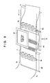
- FIG. 9 is a perspective view showing a state in which the print media pass through an image reading area of the inspection unit.
- FIG. 9 a state is shown in which the plurality of print media P, onto which images are transferred and which are gripped by grip mechanisms 8 e , are conveyed continuously in a direction from the right to the left as indicated by the arrow A.
- the preceding print medium P reaches between a detection surface 9 F of the inspection unit 9 B and the elevating unit 9 D of the lift-up unit 9 C, and the succeeding print medium P reaches a conveyance guide 9 E on the right side.
- Each of these grip mechanisms 8 e is fixed to a chain clipper 8 f , and the chain clipper 8 f engages with the chain 8 c .
- the print media P are thus conveyed in the direction of the arrow A along with the circulation of the chain 8 c.
- the elevating unit 9 D can move in a direction of an arrow B perpendicular to the arrow A. This makes it possible to press the print medium P that reaches between the detection surface 9 F and the elevating unit 9 D against the detection surface 9 F.
- the quality of the images printed by the printing system is inspected by performing image processing for stopping conveyance of the print medium P, further pressing and fixing the print medium P, and causing the scanner to read the images at a predetermined interval in the conveyance direction of the print medium. The inspection of a printed product printed on the print medium P is thus performed.
- FIG. 10 shows views and a flowchart of a state in which images are read by causing the print medium to pass through the image reading area of the inspection unit.
- FIG. 10 shows the views in which the inspection unit 9 B and the lift-up unit 9 C are viewed in a direction perpendicular to the arrow A indicating the conveyance direction of the print media and the arrow B indicating the moving direction of the elevating unit 9 D in FIG. 9 (a direction perpendicular to a sheet surface).
- step S 110 the print medium P gripped by the grip mechanisms 8 e is conveyed immediately below the scanner 9 B by rotating the chain 8 c engaged with the chain clippers 8 f .
- the elevating unit 9 D of the lift-up unit 9 C is at a position (first position) retracted from the conveyance path of the print medium so as not to impede conveyance of the print medium P.
- step S 120 conveyance of the print medium P is stopped when an image 100 that is printed on the print medium P shown on the right side of FIG. 10 reaches the reading area of the scanner 9 B. Then, the elevating unit 9 D of the lift-up unit 9 C is moved upward (second position) to press/fix the print medium P against/to the detection surface 9 F of the scanner 9 B, reading the area of the image 100 by the scanner 9 B. In this reading process, an image of 850-mm width ⁇ 210-mm length corresponding to the swath image 100 is read once.
- step S 130 the elevating unit 9 D of the lift-up unit 9 C is moved downward (first position) again. Then, conveyance of the print medium P gripped by the grip mechanisms 8 e is resumed until an image 200 printed on the print medium P reaches the reading area of the scanner 9 B by rotating the chain 8 c engaged with the chain clippers 8 f.
- step S 140 the elevating unit 9 D of the lift-up unit 9 C is moved upward (second position) again to press/fix the print medium P against/to the detection surface 9 F of the scanner 9 B, reading the area of the image 200 by the scanner 9 B.
- an image of 850-mm width ⁇ 210-mm length corresponding to the swath image 200 is read at once.
- step S 150 the elevating unit 9 D of the lift-up unit 9 C is moved downward (first position) to discharge the print medium P from the inspection unit 9 B.
- FIG. 11 is a view showing a relationship among the detection surface, the print medium P, and the size of the elevating unit concerning the conveyance direction of the print medium when the print medium P is pressed.
- a size W 2 of the elevating unit 9 D used to press the print medium P and fix the print medium P is greater in length than a size W 1 of the detection surface 9 F of the scanner 9 B (W 2 >W 1 ) with respect to the conveyance direction of the print medium P. This fixes the print medium P reliably so as not to cause an image reading deviation when the inspection unit reads the swath images.
- the elevating unit 9 D of the lift-up unit 9 C is configured to move upward/downward in order to press the print medium P.
- An arrangement may be possible, however, in which the detection surface 9 F of the scanner 9 B is moved to press the print medium P.
- the elevating unit 9 D is configured to move between the first position retracted from the conveyance path of the print medium P and the second position in which the print medium P is pressed, and to stop at these two positions.
- the present invention is not, however, limited to this configuration.
- the elevating unit 9 D may be configured to also stop at the third position between the first position and the second position, which is retracted from the conveyance path of the print medium, but at which the print medium P is not pressed.
- FIG. 12 is a view showing a state in which the elevating unit 9 D stops at the third position.
- FIGS. 13A and 13B are views each showing a state in which an image is read by causing a print medium P to pass through an image reading area of an inspection unit according to another embodiment.
- FIG. 13A shows a state in which the image is read by causing the print medium P to pass through the image reading area of the inspection unit with the arrangement in the aforementioned embodiment.
- FIG. 13B shows a state in which the image is read by causing the print medium P to pass through the image reading area of the inspection unit according to the other embodiment.
- FIGS. 13A and 13B show a state in which a print medium P is conveyed from the right to the left and passes through the inspection unit.
- the trailing edge portion of the print medium P becomes free and does not receive any regulation, resulting in a portion indicated by a broken-line circle L slacking.
- the print medium P (image) may be scratched by such a slack when the scanner reads the image.
- a pair of pinch rollers 9 G are provided on the upstream side of the scanner 9 B in a conveyance direction of the print medium.
- the trailing edge portion of the print medium P is pinched on the upstream side of the scanner in the conveyance direction, and thus, the print medium P is neither slacked nor scratched even if the print medium P is pressed/fixed against/to the scanner.
- the print unit 3 includes the plurality of printheads 30 .
- a print unit 3 may, however, include one printhead 30 .
- the printhead 30 may not be a full-line head, and may be of a serial type that forms an ink image while scanning the printhead 30 in a Y direction.
- a conveyance mechanism of the print medium P may adopt another method, such as a method of clipping and conveying the print medium P by the pair of rollers.
- a roll sheet may be used as the print medium P, and a printed product P′ may be formed by cutting the roll sheet after transfer.
- the transfer member 2 is provided on the outer peripheral surface of the transfer drum 41 .
- Another method such as a method of forming a transfer member 2 into an endless swath and running it cyclically, may, however, be used.
- Embodiments of the present invention can also be realized by a computer of a system or an apparatus that reads out and executes computer executable instructions (e.g., one or more programs) recorded on a storage medium (which may also be referred to more fully as a ‘non-transitory computer-readable storage medium’) to perform the functions of one or more of the above-described embodiments and/or that includes one or more circuits (e.g., an application specific integrated circuit (ASIC)) for performing the functions of one or more of the above-described embodiments, and by a method performed by the computer of the system or the apparatus by, for example, reading out and executing the computer executable instructions from the storage medium to perform the functions of one or more of the above-described embodiments and/or controlling the one or more circuits to perform the functions of one or more of the above-described embodiments.
- ASIC application specific integrated circuit
- the computer may comprise one or more processors (e.g., a central processing unit (CPU), or a micro processing unit (MPU)) and may include a network of separate computers or separate processors to read out and to execute the computer executable instructions.
- the computer executable instructions may be provided to the computer, for example, from a network or the storage medium.
- the storage medium may include, for example, one or more of a hard disk, a random-access memory (RAM), a read only memory (ROM), a storage of distributed computing systems, an optical disk (such as a compact disc (CD), a digital versatile disc (DVD), or a Blu-ray Disc (BD)TM) a flash memory device, a memory card, and the like.
Landscapes
- Engineering & Computer Science (AREA)
- Mechanical Engineering (AREA)
- Quality & Reliability (AREA)
- Ink Jet (AREA)
- Facsimiles In General (AREA)
- Facsimile Scanning Arrangements (AREA)
Applications Claiming Priority (2)
| Application Number | Priority Date | Filing Date | Title |
|---|---|---|---|
| JP2017027273A JP2018133742A (ja) | 2017-02-16 | 2017-02-16 | 記録装置、検査装置及びその制御方法 |
| JP2017-027273 | 2017-02-16 |
Publications (2)
| Publication Number | Publication Date |
|---|---|
| US20180229518A1 US20180229518A1 (en) | 2018-08-16 |
| US10486441B2 true US10486441B2 (en) | 2019-11-26 |
Family
ID=63106116
Family Applications (1)
| Application Number | Title | Priority Date | Filing Date |
|---|---|---|---|
| US15/891,848 Expired - Fee Related US10486441B2 (en) | 2017-02-16 | 2018-02-08 | Printing apparatus, inspection apparatus, and method of controlling the inspection apparatus in which a fixing unit fixes a relative position between a detection surface of a reading unit and a print medium |
Country Status (2)
| Country | Link |
|---|---|
| US (1) | US10486441B2 (ja) |
| JP (1) | JP2018133742A (ja) |
Families Citing this family (2)
| Publication number | Priority date | Publication date | Assignee | Title |
|---|---|---|---|---|
| JP2022528114A (ja) * | 2019-04-03 | 2022-06-08 | ランダ コーポレイション リミテッド | シートへの損傷をなくすための回転要素が設けられたシートコンベヤを有するデジタル印刷システム |
| JP2020194028A (ja) * | 2019-05-27 | 2020-12-03 | コニカミノルタ株式会社 | 測定装置、画像形成装置及び測定方法 |
Citations (2)
| Publication number | Priority date | Publication date | Assignee | Title |
|---|---|---|---|---|
| US20030194252A1 (en) * | 2002-04-12 | 2003-10-16 | Canon Kabushiki Kaisha | Image forming apparatus |
| JP2013228640A (ja) | 2012-04-26 | 2013-11-07 | Canon Inc | 画像形成装置 |
-
2017
- 2017-02-16 JP JP2017027273A patent/JP2018133742A/ja active Pending
-
2018
- 2018-02-08 US US15/891,848 patent/US10486441B2/en not_active Expired - Fee Related
Patent Citations (2)
| Publication number | Priority date | Publication date | Assignee | Title |
|---|---|---|---|---|
| US20030194252A1 (en) * | 2002-04-12 | 2003-10-16 | Canon Kabushiki Kaisha | Image forming apparatus |
| JP2013228640A (ja) | 2012-04-26 | 2013-11-07 | Canon Inc | 画像形成装置 |
Also Published As
| Publication number | Publication date |
|---|---|
| US20180229518A1 (en) | 2018-08-16 |
| JP2018133742A (ja) | 2018-08-23 |
Similar Documents
| Publication | Publication Date | Title |
|---|---|---|
| US11072177B2 (en) | Liquid absorbing apparatus, printing apparatus, printing method, and manufacturing method | |
| US10500839B2 (en) | Inkjet printing apparatus and related printing method in which a liquid applied to a transfer member is dried before ink is discharged by a printhead | |
| US20190009594A1 (en) | Printing apparatus, liquid absorbing apparatus, and control method | |
| US20190009546A1 (en) | Printing apparatus, liquid absorbing apparatus, and control method | |
| US10486417B2 (en) | Printing apparatus | |
| US20190009515A1 (en) | Printing apparatus and printing method thereof | |
| US10755151B2 (en) | Inkjet printing apparatus and control method therefor | |
| US20190009589A1 (en) | Printing apparatus, liquid absorbing apparatus, control method | |
| US10252516B2 (en) | Printing apparatus, liquid absorbing apparatus, and method | |
| US10493782B2 (en) | Inkjet printing apparatus and related temperature control method that control cooling and heating of a transfer member | |
| US10538081B2 (en) | Printing apparatus, liquid absorbing apparatus, and printing method | |
| US10486441B2 (en) | Printing apparatus, inspection apparatus, and method of controlling the inspection apparatus in which a fixing unit fixes a relative position between a detection surface of a reading unit and a print medium | |
| US20180257369A1 (en) | Printing apparatus and adjustment method thereof | |
| US10421271B2 (en) | Printing apparatus and control method | |
| US10611140B2 (en) | Inkjet printing apparatus | |
| US10350894B2 (en) | Printing apparatus | |
| US10427427B2 (en) | Printing apparatus that detects whether a print medium runs out and, during double-sided printing, discards image data to be printed on the run out print medium, and related print control method | |
| US10543678B2 (en) | Printing apparatus that specifies a region of a transfer member having a poor surface condition and prohibits printing in the region, and related print control method | |
| US10618274B2 (en) | Printing apparatus and control method | |
| US20200047529A1 (en) | Printing apparatus, cleaning device, and printing method | |
| US20180290469A1 (en) | Printing apparatus | |
| US20200047487A1 (en) | Printing apparatus, and printing method | |
| US10369780B2 (en) | Printing apparatus | |
| US10464309B2 (en) | Printing apparatus and control method | |
| US10493781B2 (en) | Printing apparatus, liquid absorbing apparatus, and control method |
Legal Events
| Date | Code | Title | Description |
|---|---|---|---|
| FEPP | Fee payment procedure |
Free format text: ENTITY STATUS SET TO UNDISCOUNTED (ORIGINAL EVENT CODE: BIG.); ENTITY STATUS OF PATENT OWNER: LARGE ENTITY |
|
| AS | Assignment |
Owner name: CANON KABUSHIKI KAISHA, JAPAN Free format text: ASSIGNMENT OF ASSIGNORS INTEREST;ASSIGNORS:MASUDA, MIKA;ASANO, SHINYA;HORIBA, TAKASHI;SIGNING DATES FROM 20180515 TO 20180516;REEL/FRAME:047229/0580 |
|
| STPP | Information on status: patent application and granting procedure in general |
Free format text: NON FINAL ACTION MAILED |
|
| STPP | Information on status: patent application and granting procedure in general |
Free format text: RESPONSE TO NON-FINAL OFFICE ACTION ENTERED AND FORWARDED TO EXAMINER |
|
| STPP | Information on status: patent application and granting procedure in general |
Free format text: NOTICE OF ALLOWANCE MAILED -- APPLICATION RECEIVED IN OFFICE OF PUBLICATIONS |
|
| STPP | Information on status: patent application and granting procedure in general |
Free format text: PUBLICATIONS -- ISSUE FEE PAYMENT VERIFIED |
|
| STCF | Information on status: patent grant |
Free format text: PATENTED CASE |
|
| FEPP | Fee payment procedure |
Free format text: MAINTENANCE FEE REMINDER MAILED (ORIGINAL EVENT CODE: REM.); ENTITY STATUS OF PATENT OWNER: LARGE ENTITY |
|
| LAPS | Lapse for failure to pay maintenance fees |
Free format text: PATENT EXPIRED FOR FAILURE TO PAY MAINTENANCE FEES (ORIGINAL EVENT CODE: EXP.); ENTITY STATUS OF PATENT OWNER: LARGE ENTITY |
|
| STCH | Information on status: patent discontinuation |
Free format text: PATENT EXPIRED DUE TO NONPAYMENT OF MAINTENANCE FEES UNDER 37 CFR 1.362 |
|
| FP | Lapsed due to failure to pay maintenance fee |
Effective date: 20231126 |