US10478905B2 - Machine tool for forming radiating cable - Google Patents
Machine tool for forming radiating cable Download PDFInfo
- Publication number
- US10478905B2 US10478905B2 US15/705,409 US201715705409A US10478905B2 US 10478905 B2 US10478905 B2 US 10478905B2 US 201715705409 A US201715705409 A US 201715705409A US 10478905 B2 US10478905 B2 US 10478905B2
- Authority
- US
- United States
- Prior art keywords
- carriage
- cable
- axis
- pattern
- receiving channel
- Prior art date
- Legal status (The legal status is an assumption and is not a legal conclusion. Google has not performed a legal analysis and makes no representation as to the accuracy of the status listed.)
- Active, expires
Links
- 239000004020 conductor Substances 0.000 claims abstract description 75
- 238000003801 milling Methods 0.000 claims abstract description 60
- 238000004891 communication Methods 0.000 claims abstract description 16
- 238000005520 cutting process Methods 0.000 claims abstract description 12
- 230000009471 action Effects 0.000 claims abstract description 11
- 238000000034 method Methods 0.000 claims description 17
- 125000006850 spacer group Chemical group 0.000 claims description 12
- 239000003989 dielectric material Substances 0.000 description 15
- 238000013461 design Methods 0.000 description 6
- 230000008569 process Effects 0.000 description 5
- 238000004026 adhesive bonding Methods 0.000 description 4
- 239000007767 bonding agent Substances 0.000 description 4
- 229910052751 metal Inorganic materials 0.000 description 4
- 239000002184 metal Substances 0.000 description 4
- RYGMFSIKBFXOCR-UHFFFAOYSA-N Copper Chemical compound [Cu] RYGMFSIKBFXOCR-UHFFFAOYSA-N 0.000 description 3
- 229910052782 aluminium Inorganic materials 0.000 description 3
- XAGFODPZIPBFFR-UHFFFAOYSA-N aluminium Chemical compound [Al] XAGFODPZIPBFFR-UHFFFAOYSA-N 0.000 description 3
- 229910052802 copper Inorganic materials 0.000 description 3
- 239000010949 copper Substances 0.000 description 3
- 238000004519 manufacturing process Methods 0.000 description 3
- 239000000463 material Substances 0.000 description 3
- 230000001681 protective effect Effects 0.000 description 3
- 238000003860 storage Methods 0.000 description 3
- 230000006835 compression Effects 0.000 description 2
- 238000007906 compression Methods 0.000 description 2
- 238000013500 data storage Methods 0.000 description 2
- 238000001125 extrusion Methods 0.000 description 2
- -1 polytetrafluorethylene Polymers 0.000 description 2
- 238000012545 processing Methods 0.000 description 2
- 239000007787 solid Substances 0.000 description 2
- 239000004698 Polyethylene Substances 0.000 description 1
- 229910000831 Steel Inorganic materials 0.000 description 1
- 230000001133 acceleration Effects 0.000 description 1
- 230000005540 biological transmission Effects 0.000 description 1
- 230000015572 biosynthetic process Effects 0.000 description 1
- 238000007664 blowing Methods 0.000 description 1
- 230000015556 catabolic process Effects 0.000 description 1
- 230000008859 change Effects 0.000 description 1
- 235000019504 cigarettes Nutrition 0.000 description 1
- 239000000356 contaminant Substances 0.000 description 1
- 238000010924 continuous production Methods 0.000 description 1
- 238000006731 degradation reaction Methods 0.000 description 1
- 230000005670 electromagnetic radiation Effects 0.000 description 1
- 230000007613 environmental effect Effects 0.000 description 1
- 239000011888 foil Substances 0.000 description 1
- 230000006870 function Effects 0.000 description 1
- 238000009434 installation Methods 0.000 description 1
- 239000011810 insulating material Substances 0.000 description 1
- 238000003475 lamination Methods 0.000 description 1
- 230000007246 mechanism Effects 0.000 description 1
- 238000012986 modification Methods 0.000 description 1
- 230000004048 modification Effects 0.000 description 1
- 230000036961 partial effect Effects 0.000 description 1
- 239000004033 plastic Substances 0.000 description 1
- 229920003023 plastic Polymers 0.000 description 1
- 229920000573 polyethylene Polymers 0.000 description 1
- 229920001343 polytetrafluoroethylene Polymers 0.000 description 1
- 238000004080 punching Methods 0.000 description 1
- 230000004044 response Effects 0.000 description 1
- 239000010959 steel Substances 0.000 description 1
- 239000002699 waste material Substances 0.000 description 1
- 238000003466 welding Methods 0.000 description 1
Images


Classifications
-
- B—PERFORMING OPERATIONS; TRANSPORTING
- B23—MACHINE TOOLS; METAL-WORKING NOT OTHERWISE PROVIDED FOR
- B23C—MILLING
- B23C3/00—Milling particular work; Special milling operations; Machines therefor
- B23C3/28—Grooving workpieces
- B23C3/34—Milling grooves of other forms, e.g. circumferential
-
- B—PERFORMING OPERATIONS; TRANSPORTING
- B23—MACHINE TOOLS; METAL-WORKING NOT OTHERWISE PROVIDED FOR
- B23C—MILLING
- B23C3/00—Milling particular work; Special milling operations; Machines therefor
- B23C3/002—Milling elongated workpieces
-
- G—PHYSICS
- G05—CONTROLLING; REGULATING
- G05B—CONTROL OR REGULATING SYSTEMS IN GENERAL; FUNCTIONAL ELEMENTS OF SUCH SYSTEMS; MONITORING OR TESTING ARRANGEMENTS FOR SUCH SYSTEMS OR ELEMENTS
- G05B19/00—Programme-control systems
- G05B19/02—Programme-control systems electric
- G05B19/18—Numerical control [NC], i.e. automatically operating machines, in particular machine tools, e.g. in a manufacturing environment, so as to execute positioning, movement or co-ordinated operations by means of programme data in numerical form
- G05B19/182—Numerical control [NC], i.e. automatically operating machines, in particular machine tools, e.g. in a manufacturing environment, so as to execute positioning, movement or co-ordinated operations by means of programme data in numerical form characterised by the machine tool function, e.g. thread cutting, cam making, tool direction control
-
- B—PERFORMING OPERATIONS; TRANSPORTING
- B23—MACHINE TOOLS; METAL-WORKING NOT OTHERWISE PROVIDED FOR
- B23C—MILLING
- B23C2220/00—Details of milling processes
- B23C2220/08—Milling with the axis of the tool perpendicular to the workpiece axis
-
- B—PERFORMING OPERATIONS; TRANSPORTING
- B23—MACHINE TOOLS; METAL-WORKING NOT OTHERWISE PROVIDED FOR
- B23C—MILLING
- B23C2220/00—Details of milling processes
- B23C2220/36—Production of grooves
-
- G—PHYSICS
- G05—CONTROLLING; REGULATING
- G05B—CONTROL OR REGULATING SYSTEMS IN GENERAL; FUNCTIONAL ELEMENTS OF SUCH SYSTEMS; MONITORING OR TESTING ARRANGEMENTS FOR SUCH SYSTEMS OR ELEMENTS
- G05B2219/00—Program-control systems
- G05B2219/30—Nc systems
- G05B2219/37—Measurements
- G05B2219/37355—Cutting, milling, machining force
Definitions
- Radiating cables generally have a coaxial cable that includes an inner conductor surrounded by an outer conductor of tubular form, and a dielectric layer interposed between the two conductors.
- the outer conductor includes slots which generate an electromagnetic radiation.
- the outer conductor is covered by an insulating outer sheath.
- the slots in the outer conductor may be of various types, for example a longitudinal slot over the entire length of the cable, or numerous small holes very close to each other.
- the radiating cables may operate in a “coupled mode” or a “radiated mode.”
- a coupled mode the total length of the outer conductor includes slots that are separated by a distance considerably shorter than the wavelength of the radiated signal, and the radiated energy propagates in a direction parallel to the cable.
- the signal received by a receiving antenna dissipates rapidly when the distance between the antenna and the cable increases, and the received signal fluctuates greatly when the receiving antenna is moved along a path parallel to the cable.
- the outer conductor includes groups of slots, which are reproduced with a constant spacing, this spacing being of the same order of magnitude as the wavelength of the signal to be radiated.
- the outer conductor is typically prepared by punching holes in a suitable metal strip before folding the strip around the dielectric spacer.
- the pre-punched metal foil wrapped around the dielectric spacer is not welded and/or bonded.
- a problem associated with the manufacture of radiating coaxial by wrapping the punched metal strip around the dielectric spacer is mechanical slot compression. During wrapping, the slots are compressed in the circumferential direction with respect to the cable causing the slots to become narrower. This mechanical slot compression results in less slot area through which the cable can emit or receive a signal. This impacts the efficiency of the radiating cable and mechanical strength.
- slots in the outer conductor before wrapping can affect the mechanical properties of the cable as well.
- the slotted conductor metal sheet may be less resistant to kinking and crushing during handling and installation of the cable. Further, the resistance to environmental conditions such as moisture ingress into the dielectric core can also be reduced. Each of these problems may lead to electrical degradation of the cable.
- a system for forming a radiating cable includes a radiating machine tool that includes a cable receiving channel and a carriage.
- the carriage includes an aperture configured to align with the cable receiving channel, and a milling motor having a milling cutter.
- a radiating machine tool also includes a carriage receiving structure.
- the carriage receiving structure is configured to engage an end of the carriage and cause the carriage to rotate about an axis that is coaxial with the cable receiving channel such that the milling cutter is oriented in a direction perpendicular to the axis.
- a radiating machine tool is in communication with one or more controllers.
- the one or more controllers are configured to receive a feeding speed associated with feeding a coaxial cable into the cable receiving channel, receive a pattern, determine a speed of rotation of the carriage by analyzing the feeding speed and the pattern, cause the carriage to rotate about the axis at the determined speed, and cause the milling cutter to perform one or more cutting actions to create one or more slots forming at least a portion of the pattern in an outer conductor of the coaxial cable.
- the one or more controllers may be configured to cause the milling cutter to perform one or more in-and-out movements.
- the one or more controllers may be configured to cause the carriage receiving structure to move in a direction perpendicular to the axis.
- the carriage may include two milling motors that are disposed at diametrically opposite ends of the aperture.
- the carriage may be attached to the carriage receiving structure.
- the radiating machine tool may include one or more second carriages.
- Each of the second carriages may include a second aperture configured to align with the cable receiving channel, and a second milling motor comprising a second milling cutter.
- the carriage receiving structure may be further configured to engage an end of one or more of the second carriages and cause one or more of the second carriages to rotate about the axis such that the second milling cutter of the one or more second carriages is oriented in the direction perpendicular to the axis.
- the controller may be configured to cause one or more of the second milling cutters to perform one or more cutting actions to create one or more slots forming at least a second portion of the pattern in an outer conductor of the coaxial cable. Rotation of the carriage and rotation of the one or more second carriages may be controlled independently of one another.
- a system for forming a radiating cable includes a radiating machine tool that includes a cable receiving channel and a plurality of carriages. Each carriage includes an aperture configured to align with the cable receiving channel, and a milling motor having a milling cutter.
- the radiating machine tool includes a carriage receiving structure configured to engage an end of each carriage and cause each carriage to rotate about an axis that is coaxial with the cable receiving channel such that the milling cutter of the carriage is oriented in a direction perpendicular to the axis.
- the radiating machine tool is in communication with one or more controllers.
- the one or more controllers are configured to receive a feeding speed associated with feeding a coaxial cable into the cable receiving channel, receive a pattern, determine a speed of rotation of the carriage by analyzing the feeding speed and the pattern, cause one or more of the carriages to rotate about the axis at the determined speed, and cause one or more of the milling cutters of the one or more carriages to perform one or more cutting actions to create one or more slots forming at least a portion of the pattern in an outer conductor of the coaxial cable.
- the one or more controllers may be configured to cause the carriage receiving structure to move in a direction perpendicular to the axis.
- each carriage may be attached to the carriage receiving structure.
- Rotation of carriages may be controlled independently of one another.
- a method of forming a radiating cable includes forming, by a radiating machine tool, a plurality of slots along a longitudinal length of an outer conductor of a coaxial cable by: receiving, by a cable receiving channel of the radiating machine tool, the coaxial cable, where the coaxial cable passes through an aperture of a carriage of the radiating machine tool, and causing, by a controller in communication with the radiating machine tool, the carriage to rotate about an axis that is coaxial with the cable receiving channel such that one or more milling cutters of the carriage form one or more of the plurality of slots along the longitudinal length of the outer conductor.
- the method further includes receiving a feeding speed associated with feeding the coaxial cable into the cable receiving channel, receiving a pattern, and determining a speed of rotation of the carriage by analyzing the feeding speed and the pattern.
- Causing the carriage to rotate about the axis may include causing the carriage to rotate about the axis at the determined speed.
- the method further includes receiving a pattern.
- Causing the carriage to rotate about the axis that is coaxial with the cable receiving channel such that one or more milling cutters of the carriage form one or more of the plurality of slots along the longitudinal length of the outer conductor may include causing the carriage to rotate about the axis such that one or more of the milling cutters performs one or more cutting actions to create the one or more slots forming at least a portion of the pattern.
- the method may include providing an inner conductor, adding a dielectric spacer over the inner conductor, and forming the outer conductor disposed over the dielectric spacer to form the coaxial cable.
- the method may include causing, by the controller, one or more second carriages to rotate about the axis such that one or more milling cutters of the second carriage form one or more of the plurality of slots along the longitudinal length of the outer conductor.
- FIG. 1 illustrates a partially broken away side perspective view illustrating an example radiating coaxial cable, according to an embodiment.
- FIG. 2 illustrates a top view of example slot patterns created in an outer conductor of an example radiating coaxial cable, according to an embodiment.
- FIG. 3 illustrates a flowchart for an example method of manufacturing a radiating coaxial cable, according to an embodiment.
- FIG. 4A and FIG. 4B illustrate a schematic front perspective view of an example radiating machine tool, according to an embodiment.
- FIGS. 4C and 4D illustrate different views of a carriage of an example radiating machine tool, according to an embodiment.
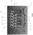
- FIG. 4E illustrates a front view of an example radiating machine tool in which a coaxial cable is fed through a channel, according to an embodiment.
- FIG. 4F illustrates an example system according to an embodiment.
- FIG. 5 illustrates example parameters and associated values for creating the slot design of FIG. 2 , according to an embodiment.
- first component may be an “upper” component and a second component may be a “lower” component when a light fixture is oriented in a first direction.
- the relative orientations of the components may be reversed, or the components may be on the same plane, if the orientation of a light fixture that contains the components is changed.
- the claims are intended to include all orientations of a device containing such components.
- computer-readable storage medium each refer to a non-transitory device on which computer-readable data, programming instructions or both are stored. Unless the context specifically states that a single device is required or that multiple devices are required, the terms “computer-readable storage medium,” “data storage facility,” and “memory” include both the singular and plural embodiments, as well as portions of such devices such as memory sectors.
- controller refers to a control apparatus for controlling one or more mechanical units or devices of a machine tool.
- a controller may be a digital controller, an analog controller or circuit, an integrated circuit (IC), a programmable logic controller (PLC), a microcontroller, and/or the like.
- controller may refer to either a single controller or to multiple controllers that together implement various steps of a process. Unless the context specifically states that a single controller is required or that multiple controllers are required, the term “controller” includes both the singular and plural embodiments.
- processor and “processing device” refer to a hardware component of a controller or an electronic device that is configured to execute programming instructions.
- the term “processor” may refer to either a single processor or to multiple processors that together implement various steps of a process. Unless the context specifically states that a single processor is required or that multiple processors are required, the term “processor” includes both the singular and plural embodiments.
- a radiating cable 100 may include a coaxial cable, having an inner conductor 101 that is surrounded by an outer conductor 103 , and a dielectric material 102 disposed between the inner conductor 101 and the outer conductor 103 .
- the inner conductor 101 may be formed from any electrically conducting material such as copper, aluminum, or copper plated steel, and may be provided in stranded wire or tubular form.
- the inner conductor 101 may be solid, hollow, stranded, corrugated, plated, clad, or the like.
- the inner conductor 101 may be a copper-clad aluminum wire, such as for microwave coax applications.
- the outer conductor 103 may be formed from any electrically conductive material such as copper or aluminum, and defines the circumference of a radiating cable.
- a protective jacket 104 may surround outer conductor 103 to protect the contents of a radiating cable. Any insulating material may be used for jacket 104 , such as, for example, rubber or non-conductive plastic.
- the inner conductor 101 and the outer conductor 103 may be separated by a dielectric material.
- a dielectric material For example, one or more circular disc-shaped spacers may be concentrically disposed at axial intervals about the inner conductor 101 to form the dielectric material such that the inner conductor 101 passes through an axial hole included in one or more of the one or more spacers.
- the dielectric spacer may be a continuous solid 102 such as a sheath between the inner conductor 101 and the outer conductor 103 .
- the dielectric spacer may be formed from any suitable dielectric material such as polytetrafluorethylene or polyethylene (foamed or unfoamed), laminates, or any other material or combination of materials.
- the dielectric material may be surrounded by a sleeve that provides additional protection against moisture ingress, such as in cases where the outer insulating jacket of the cable is damaged.
- the outer conductor 103 may include a plurality of slots 111 a, 111 b, . . . , 111 n, spaced longitudinally from each other a uniform and/or variable distance D, along the length of the radiating cable such that they form one or more patterns 112 a, 112 b, 112 c, 112 d.
- the slots may be of any shape such as circular, rectangular, oval, or the like, and may extend at an oblique angle relative to a center axis C extending along the longitudinal center of the radiating cable 100 .
- the patterns of slots may be symmetrically arranged on diametrically opposite sides (in a direction perpendicular to the center axis C) of the radiating cable 100 .
- FIG. 3 illustrates a flowchart for an example method of manufacturing a radiating cable, such as the radiating cable of FIG. 1 or FIG. 2 , according to an embodiment.
- an inner conductor is provided in 301 , and dielectric material may be positioned 302 around the inner conductor.
- the dielectric material may be molded or extruded directly onto an inner conductor.
- the inner conductor may be fed through an extruder where a pre-coat of an adhesive bonding agent is applied.
- the pre-coated inner conductor may then be fed through an extruder where the dielectric spacers are applied at predetermined positions around the inner conductor.
- the dielectric material may be molded in advance and positioned in the appropriate configuration around the inner conductor.
- the inner conductor may be heated before application of the adhesive bonding to an elevated temperature to remove moisture or other contaminants on the surface of the conductor.
- an optional insulating sleeve may be extruded or otherwise formed over the dielectric material.
- heat from the extrusion process may create a heat bond between the sleeve and the dielectric material.
- an adhesive bonding agent may be applied on the circumference of the dielectric material.
- an outer conductor may be drawn, helically wound, longitudinally pulled (cigarette wrapped), braided, extruded, plated, or applied using any now or hereafter known methods, over the dielectric material to form a coaxial cable.
- the inner conductor surrounded by the dielectric material may be fed through an extruder where a pre-coat of an adhesive bonding agent is applied over the dielectric material.
- the pre-coated structure may then be fed through an extruder where the outer conductor is applied.
- a strip of the outer conductor may be seam welded (such as using a high-speed welding process) into a tubular configuration, which is then drawn over the dielectric material in a continuous process.
- a plurality of slots may be formed into the outer conductor using a radiating machine tool.
- any waste material created during formation of the slots may be removed using methods such as suction, blowing, and/or the like.
- the radiating machine tool may be configured to cut slots in the outer conductor that can be of a desired width, length or angle in either a linear or a non-linear mode.
- FIG. 4A and FIG. 4B illustrate front perspective views of an example radiating machine tool.
- a radiating machine tool may be in communication with a controller that is configured to operate the radiating machine tool in a desired manner.
- a controller or a computer-readable storage medium associated with a controller
- the controller may access drives that run the motors of one or more components on the radiating machine tool, and may provide the digital and analog inputs to create the desired movements.
- a controller 420 may be in communication with a machine tool 400 over a communication network 422 .
- a communication network may be a wired or wireless communication network.
- one or more controllers 420 may be in communication with an electronic device 421 such as, for example, a desktop computer, a laptop computer, a tablet, a mobile device and/or the like.
- a controller 420 may communicate with an electronic device 421 via a communication network 423 .
- a user may utilize an electronic device to adjust, change, or update the programming of one or more controllers.
- the radiating machine tool 400 may include one or more carriages 401 a, 401 b, 401 c, 401 d, 401 e configured to rotate around a longitudinal axis (X-axis) of a cable receiving channel 402 of the radiating machine tool.
- a cable receiving channel 402 includes one or more cable receiving apertures (not shown here).
- each carriage 401 may also include an aperture 412 , and one or more milling motors 411 a and 411 b (each including a milling cutter or bit, not shown here).
- a milling cutter or a milling bit may be directly received into the milling motor.
- a milling motor may include and/or be in communication with a milling head that received the milling cutter or milling bit.
- the milling motors 411 a and 411 b may be positioned diametrically opposite to each other, and may be independently controlled to move in or out of a cutting position.
- a carriage may include only one milling motor configured to cut slots on one side of a coaxial cable.
- a carriage 401 is configured to be attached to the radiating machine tool 400 such that the cable receiving apertures of the cable receiving channel 402 and the aperture 412 of the carriage 401 are aligned and/or concentric (i.e., the center of the aperture 412 coincides with the longitudinal axis (X-axis) of the cable receiving channel 402 ).
- the cable receiving channel 402 and aperture 412 of the carriage 401 may substantially have the same circumferential diameter.
- a coaxial cable may be fed through the cable receiving channel 402 such that it passes through an aperture 412 of carriage 401 attached to the radiating machine tool 400 .
- a milling cutter may project within the cable receiving channel 402 and/or the aperture 412 when its milling motor is in a cutting position, and may be configured to form slots of a desired width in the outer conductor through one or more cutting actions such as, for example, in-and-out movements.
- the carriages 401 a, 401 b, 401 c, 401 d, 401 e may be attached to a supporting structure 403 , such that each carriage has a free end ( 413 a, 413 b, 413 c, 413 d, 413 e ), and an end ( 414 a, 414 b, 414 c, 414 d, 414 e ) configured to be attached to a corresponding moveable carriage receiving structure 404 (separate for each carriage, but not shown here) of the supporting structure 403 .
- Each carriage receiving structure 404 may move in a direction perpendicular to the longitudinal axis of the cable receiving channel 402 , such that movement of a carriage receiving structure 404 causes the attached corresponding carriage to rotate about an axis that is coaxial with the longitudinal axis of cable receiving channel 402 .
- Rotation of a carriage may be controlled independently of the other carriages.
- a milling motor of a carriage may be configured to be included in the carriage such that its milling cutter is orientated in a direction perpendicular to the X-axis and this orientation is maintained during rotation of the carriage.
- the depth of a slot formed is kept uniform and is controlled such that the slots are only formed in the outer conductor of the coaxial cable.
- a coaxial cable 450 with an outer conductor may be fed into a receiving end 402 ( a ) of the cable receiving channel 402 at a controlled speed to obtain a coaxial cable with slots of a desired pattern formed in the outer conductor from the output end 402 ( b ) as shown in FIG. 4E .
- a controller associated with the radiating machine tool may be configured to control the feeding speed of the coaxial cable.
- a wheel or a belt may be configured to be in physical contact with the moving coaxial cable (while being fed into the cable receiving channel) and may be used to determine a feeding speed of the coaxial cable.
- That determined feeding speed may be used by the controller as feedback to control power input to a pulling mechanism (such as capstans) that pulls a radiating cable into the cable receiving channel in order to control the feeding speed of the coaxial cable.
- the controller may use the feeding speed of the coaxial cable in conjunction with a pattern associated with the plurality of slots to be formed as input to provide suitable instructions to the radiating machine tool to create the pattern.
- a controller may receive a pattern of slots to create on at least a portion of a coaxial cable. For instance, in an embodiment, a controller may receive a pattern from memory such as, for example, in response to a selection of a desired pattern by an operator.
- the controller may control the location, length, angle, or other parameters of each cut in a pattern by controlling the movement of one or more carriage receiving structures 404 and speed at which the milling motors will form slots in the outer conductor. For example, the controller may determine a speed of rotation of each carriage of the radiating machine tool based on the feeding speed of the coaxial cable and the desired pattern of slots, and control the movement of the corresponding carriage receiving structures to cause each carriage to rotate at its determined speed.
- the controller may also control the movement of the milling motors of each carriage to control engagement and disengagement of the milling cutters.
- the controller may cause the radiating machine tool to form a plurality of slots in the outer conductor, in one or more desired patterns, by controlling the feeding speed, the speed at which the milling motors will form slots, and/or engagement and disengagement of the milling cutters.
- the controller may include a processing device that is in electronic communication with one or more other components of the machine radiating tool.
- a controller may also include a memory that stores one or more programming instructions that when executed cause the controller to control movement of one or more components of the machine radiating tool to form the plurality of slots in one or more desired patterns.
- various rule sets that include information relating to one or more slot patterns (including length, width, and angle of slots, design of patterns, etc.); the movement of one or more components of the machine radiating tool required to create a slot pattern; and the corresponding one or more programming instructions that when executed cause the controller to control movement of one or more components of the machine radiating tool may be stored in memory.
- the controller may receive a desired slot pattern of slots to be created, and may access the memory to select the appropriate programming instructions to control movement of one or more components of the machine radiating tool to create the desired design pattern.
- FIG. 5 illustrates example parameters and associated values for creating the slot design of FIG. 2 .
- Values for various parameters such as a period of cut, diameter of a milling bit, cut angle, length of a slot, and distances between slots may be provided by a user and/or derived by the controller using a rule set corresponding to a desired slot design.
- the various parameters and their corresponding values provided in FIG. 5 are by way of example only and are not limiting. Additional and/or alternate parameters, values and slot designs may be used within the scope of this disclosure.
- a protective jacket may be applied to the slotted outer conductor using known processes such as extrusion, lamination, or the like.
- more than one jacket may be applied to the slotted outer conductor to improve the fire rating of a coaxial cable.
- a bonding agent may be applied on the outer surface of the outer conductor prior to application of the protective jacket.
- the extruded jacket material at high temperature may the surface of the insulating sleeve, via the slotted regions, and form a durable bond with the insulating sleeve.
Landscapes
- Engineering & Computer Science (AREA)
- Mechanical Engineering (AREA)
- Human Computer Interaction (AREA)
- Manufacturing & Machinery (AREA)
- Physics & Mathematics (AREA)
- General Physics & Mathematics (AREA)
- Automation & Control Theory (AREA)
- Removal Of Insulation Or Armoring From Wires Or Cables (AREA)
Abstract
Description
Claims (19)
Priority Applications (1)
| Application Number | Priority Date | Filing Date | Title |
|---|---|---|---|
| US15/705,409 US10478905B2 (en) | 2016-09-15 | 2017-09-15 | Machine tool for forming radiating cable |
Applications Claiming Priority (2)
| Application Number | Priority Date | Filing Date | Title |
|---|---|---|---|
| US201662394936P | 2016-09-15 | 2016-09-15 | |
| US15/705,409 US10478905B2 (en) | 2016-09-15 | 2017-09-15 | Machine tool for forming radiating cable |
Publications (2)
| Publication Number | Publication Date |
|---|---|
| US20180071837A1 US20180071837A1 (en) | 2018-03-15 |
| US10478905B2 true US10478905B2 (en) | 2019-11-19 |
Family
ID=61559481
Family Applications (1)
| Application Number | Title | Priority Date | Filing Date |
|---|---|---|---|
| US15/705,409 Active 2038-05-29 US10478905B2 (en) | 2016-09-15 | 2017-09-15 | Machine tool for forming radiating cable |
Country Status (1)
| Country | Link |
|---|---|
| US (1) | US10478905B2 (en) |
Citations (7)
| Publication number | Priority date | Publication date | Assignee | Title |
|---|---|---|---|---|
| US5339058A (en) * | 1992-10-22 | 1994-08-16 | Trilogy Communications, Inc. | Radiating coaxial cable |
| US5430255A (en) * | 1993-02-23 | 1995-07-04 | Phillips Cables Limited | Electric wires and cables and conductors for use in them |
| US5705967A (en) * | 1995-04-07 | 1998-01-06 | Institut Scientifique De Service Public | High-frequency radiating line |
| US5809429A (en) * | 1995-09-22 | 1998-09-15 | Andrew Corporation | Radiating coaxial cable and radio communication system using same |
| US5898350A (en) * | 1997-11-13 | 1999-04-27 | Radio Frequency Systems, Inc. | Radiating coaxial cable and method for making the same |
| US6480163B1 (en) * | 1999-12-16 | 2002-11-12 | Andrew Corporation | Radiating coaxial cable having helically diposed slots and radio communication system using same |
| US20110234338A1 (en) * | 2010-03-23 | 2011-09-29 | Sony Corporation | Bundled leaky transmission line, communication device, and communication system |
-
2017
- 2017-09-15 US US15/705,409 patent/US10478905B2/en active Active
Patent Citations (8)
| Publication number | Priority date | Publication date | Assignee | Title |
|---|---|---|---|---|
| US5339058A (en) * | 1992-10-22 | 1994-08-16 | Trilogy Communications, Inc. | Radiating coaxial cable |
| US5543000A (en) | 1992-10-22 | 1996-08-06 | Trilogy Communications, Inc., | Method of forming radiating coaxial cable |
| US5430255A (en) * | 1993-02-23 | 1995-07-04 | Phillips Cables Limited | Electric wires and cables and conductors for use in them |
| US5705967A (en) * | 1995-04-07 | 1998-01-06 | Institut Scientifique De Service Public | High-frequency radiating line |
| US5809429A (en) * | 1995-09-22 | 1998-09-15 | Andrew Corporation | Radiating coaxial cable and radio communication system using same |
| US5898350A (en) * | 1997-11-13 | 1999-04-27 | Radio Frequency Systems, Inc. | Radiating coaxial cable and method for making the same |
| US6480163B1 (en) * | 1999-12-16 | 2002-11-12 | Andrew Corporation | Radiating coaxial cable having helically diposed slots and radio communication system using same |
| US20110234338A1 (en) * | 2010-03-23 | 2011-09-29 | Sony Corporation | Bundled leaky transmission line, communication device, and communication system |
Also Published As
| Publication number | Publication date |
|---|---|
| US20180071837A1 (en) | 2018-03-15 |
Similar Documents
| Publication | Publication Date | Title |
|---|---|---|
| US8076612B2 (en) | Method for the continuous laying of a conductor on a printed circuit board and device for carrying out said method | |
| JP6459197B2 (en) | 2-core parallel wire | |
| JP2014157709A (en) | Insulation cable and method for manufacturing the same | |
| JPWO2015145537A1 (en) | Transmission line | |
| CN202771829U (en) | A cable used for differential signal transmission and wire beam utilizing the cable | |
| US10478905B2 (en) | Machine tool for forming radiating cable | |
| DE10247792A1 (en) | RF coaxial cable and process for its manufacture | |
| JP4374229B2 (en) | Manufacturing method of flat shielded cable | |
| JP3195110U (en) | Wiring member | |
| JP4306714B2 (en) | Antenna and manufacturing method thereof | |
| EP2232506B1 (en) | Coaxial cable including tubular bimetallic inner layer with bevelled edge joint and associated methods | |
| US20230268676A1 (en) | Prefabricated Electrical Cable, Plug Connector Assembly, and Method and Apparatus for Manufacturing an Electrical Cable | |
| US10276281B1 (en) | Communication cables with twisted tape separators | |
| US10102946B1 (en) | Methods for manufacturing discontinuous shield structures for use in communication cables | |
| JP2005158415A (en) | Coaxial cable | |
| JPWO2019131500A1 (en) | Two-core parallel wire | |
| US7687719B2 (en) | Coaxial cable including tubular bimetallic outer layer with angled edges and associated methods | |
| WO2013025500A2 (en) | Thermally conductive stripline rf transmission cable | |
| EP2232507B1 (en) | Coaxial cable including tubular bimetallic inner layer with angled edges and associated methods | |
| JP2011061677A (en) | Leakage coaxial cable and method of manufacturing the same | |
| US8138420B2 (en) | Semi-bonded shielding in a coaxial cable | |
| JP2015115301A (en) | Flat cable and flat cable assembly | |
| CN105609201B (en) | Big current-carrying power line manufacture method | |
| JP6279977B2 (en) | Waveguide | |
| CN213844869U (en) | High-performance communication cable with crosstalk barrier |
Legal Events
| Date | Code | Title | Description |
|---|---|---|---|
| AS | Assignment |
Owner name: TRILOGY COMMUNICATIONS, INC., MISSISSIPPI Free format text: ASSIGNMENT OF ASSIGNORS INTEREST;ASSIGNORS:EITEL, CHRIS A.;COOK, ERWIN SCOTT;TETRICK, CRAIG L.;AND OTHERS;REEL/FRAME:043599/0764 Effective date: 20170911 |
|
| FEPP | Fee payment procedure |
Free format text: ENTITY STATUS SET TO UNDISCOUNTED (ORIGINAL EVENT CODE: BIG.); ENTITY STATUS OF PATENT OWNER: SMALL ENTITY |
|
| FEPP | Fee payment procedure |
Free format text: ENTITY STATUS SET TO SMALL (ORIGINAL EVENT CODE: SMAL); ENTITY STATUS OF PATENT OWNER: SMALL ENTITY |
|
| STPP | Information on status: patent application and granting procedure in general |
Free format text: DOCKETED NEW CASE - READY FOR EXAMINATION |
|
| STPP | Information on status: patent application and granting procedure in general |
Free format text: NOTICE OF ALLOWANCE MAILED -- APPLICATION RECEIVED IN OFFICE OF PUBLICATIONS |
|
| STCF | Information on status: patent grant |
Free format text: PATENTED CASE |
|
| AS | Assignment |
Owner name: FIRST BUSINESS CAPITAL CORP., WISCONSIN Free format text: SECURITY INTEREST;ASSIGNOR:TRILOGY COMMUNICATIONS, INC.;REEL/FRAME:053138/0091 Effective date: 20200701 |
|
| MAFP | Maintenance fee payment |
Free format text: PAYMENT OF MAINTENANCE FEE, 4TH YR, SMALL ENTITY (ORIGINAL EVENT CODE: M2551); ENTITY STATUS OF PATENT OWNER: SMALL ENTITY Year of fee payment: 4 |