US10473682B2 - Flow meter including increased measuring detection accuracy - Google Patents
Flow meter including increased measuring detection accuracy Download PDFInfo
- Publication number
- US10473682B2 US10473682B2 US15/782,215 US201715782215A US10473682B2 US 10473682 B2 US10473682 B2 US 10473682B2 US 201715782215 A US201715782215 A US 201715782215A US 10473682 B2 US10473682 B2 US 10473682B2
- Authority
- US
- United States
- Prior art keywords
- measurement tube
- axis
- inlet
- heating resistance
- temperature detecting
- Prior art date
- Legal status (The legal status is an assumption and is not a legal conclusion. Google has not performed a legal analysis and makes no representation as to the accuracy of the status listed.)
- Active, expires
Links
- 238000001514 detection method Methods 0.000 title claims abstract description 25
- 238000005259 measurement Methods 0.000 claims abstract description 104
- 238000010438 heat treatment Methods 0.000 claims abstract description 82
- 239000007788 liquid Substances 0.000 claims abstract description 70
- 239000000758 substrate Substances 0.000 claims abstract description 65
- 239000011521 glass Substances 0.000 claims description 14
- VYPSYNLAJGMNEJ-UHFFFAOYSA-N Silicium dioxide Chemical compound O=[Si]=O VYPSYNLAJGMNEJ-UHFFFAOYSA-N 0.000 description 10
- 229920005989 resin Polymers 0.000 description 7
- 239000011347 resin Substances 0.000 description 7
- 239000000853 adhesive Substances 0.000 description 6
- 230000001070 adhesive effect Effects 0.000 description 6
- 239000000463 material Substances 0.000 description 5
- 239000000945 filler Substances 0.000 description 4
- 229920001343 polytetrafluoroethylene Polymers 0.000 description 4
- 239000004810 polytetrafluoroethylene Substances 0.000 description 4
- 230000003014 reinforcing effect Effects 0.000 description 4
- 235000012239 silicon dioxide Nutrition 0.000 description 4
- 239000000377 silicon dioxide Substances 0.000 description 4
- 230000015572 biosynthetic process Effects 0.000 description 2
- 230000007423 decrease Effects 0.000 description 2
- 230000003247 decreasing effect Effects 0.000 description 2
- 230000000694 effects Effects 0.000 description 2
- 238000009434 installation Methods 0.000 description 2
- BASFCYQUMIYNBI-UHFFFAOYSA-N platinum Chemical compound [Pt] BASFCYQUMIYNBI-UHFFFAOYSA-N 0.000 description 2
- 229920001187 thermosetting polymer Polymers 0.000 description 2
- 238000011144 upstream manufacturing Methods 0.000 description 2
- 230000007797 corrosion Effects 0.000 description 1
- 238000005260 corrosion Methods 0.000 description 1
- 238000000151 deposition Methods 0.000 description 1
- 239000003822 epoxy resin Substances 0.000 description 1
- 239000012530 fluid Substances 0.000 description 1
- 238000002844 melting Methods 0.000 description 1
- 229910052751 metal Inorganic materials 0.000 description 1
- 239000002184 metal Substances 0.000 description 1
- 229910052697 platinum Inorganic materials 0.000 description 1
- 229920000515 polycarbonate Polymers 0.000 description 1
- 239000004417 polycarbonate Substances 0.000 description 1
- 229920000647 polyepoxide Polymers 0.000 description 1
- -1 polytetrafluoroethylene Polymers 0.000 description 1
Images


Classifications
-
- G—PHYSICS
- G01—MEASURING; TESTING
- G01P—MEASURING LINEAR OR ANGULAR SPEED, ACCELERATION, DECELERATION, OR SHOCK; INDICATING PRESENCE, ABSENCE, OR DIRECTION, OF MOVEMENT
- G01P5/00—Measuring speed of fluids, e.g. of air stream; Measuring speed of bodies relative to fluids, e.g. of ship, of aircraft
- G01P5/10—Measuring speed of fluids, e.g. of air stream; Measuring speed of bodies relative to fluids, e.g. of ship, of aircraft by measuring thermal variables
-
- G—PHYSICS
- G01—MEASURING; TESTING
- G01F—MEASURING VOLUME, VOLUME FLOW, MASS FLOW OR LIQUID LEVEL; METERING BY VOLUME
- G01F1/00—Measuring the volume flow or mass flow of fluid or fluent solid material wherein the fluid passes through a meter in a continuous flow
- G01F1/68—Measuring the volume flow or mass flow of fluid or fluent solid material wherein the fluid passes through a meter in a continuous flow by using thermal effects
- G01F1/684—Structural arrangements; Mounting of elements, e.g. in relation to fluid flow
- G01F1/6847—Structural arrangements; Mounting of elements, e.g. in relation to fluid flow where sensing or heating elements are not disturbing the fluid flow, e.g. elements mounted outside the flow duct
-
- G—PHYSICS
- G01—MEASURING; TESTING
- G01F—MEASURING VOLUME, VOLUME FLOW, MASS FLOW OR LIQUID LEVEL; METERING BY VOLUME
- G01F1/00—Measuring the volume flow or mass flow of fluid or fluent solid material wherein the fluid passes through a meter in a continuous flow
- G01F1/704—Measuring the volume flow or mass flow of fluid or fluent solid material wherein the fluid passes through a meter in a continuous flow using marked regions or existing inhomogeneities within the fluid stream, e.g. statistically occurring variations in a fluid parameter
- G01F1/708—Measuring the time taken to traverse a fixed distance
- G01F1/7084—Measuring the time taken to traverse a fixed distance using thermal detecting arrangements
-
- G—PHYSICS
- G01—MEASURING; TESTING
- G01F—MEASURING VOLUME, VOLUME FLOW, MASS FLOW OR LIQUID LEVEL; METERING BY VOLUME
- G01F15/00—Details of, or accessories for, apparatus of groups G01F1/00 - G01F13/00 insofar as such details or appliances are not adapted to particular types of such apparatus
- G01F15/006—Details of, or accessories for, apparatus of groups G01F1/00 - G01F13/00 insofar as such details or appliances are not adapted to particular types of such apparatus characterised by the use of a particular material, e.g. anti-corrosive material
-
- G—PHYSICS
- G01—MEASURING; TESTING
- G01F—MEASURING VOLUME, VOLUME FLOW, MASS FLOW OR LIQUID LEVEL; METERING BY VOLUME
- G01F15/00—Details of, or accessories for, apparatus of groups G01F1/00 - G01F13/00 insofar as such details or appliances are not adapted to particular types of such apparatus
- G01F15/02—Compensating or correcting for variations in pressure, density or temperature
Definitions
- the present disclosure relates to a flow meter.
- JP 2006-10322 A thermal flow meter that controls the temperature of liquid flowing through a flow passage and measures a flow rate based on a temperature difference between the liquid on an upper stream side of a temperature control portion and the liquid on a downstream side thereof has been heretofore known (e.g., see Japanese Unexamined Patent Application, Publication No. 2006-10322 (hereinafter referred to as “JP 2006-10322”).
- JP 2006-10322 discloses a thermal flow meter having a structure in which a glass substrate is provided with a rectangular groove and a flow passage is formed by bonding the glass substrate where the groove is formed to another glass substrate provided with a heating means and a temperature detecting means that are formed on a side of the glass substrate where the groove is formed.
- the thermal flow meter preferably includes a tubular measurement tube with a straight tube portion extending linearly when measuring a very small amount of flow rate (e.g., 0.06 mL/min to 3 mL/min).
- a very small amount of flow rate e.g. 0.06 mL/min to 3 mL/min.
- the present disclosure has been made in view of the above-mentioned circumstances, and an object of the present disclosure is to increase the quantity of heat transmitted from a heating resistance element to liquid circulated in a cylindrical measurement tube in a flow meter having a structure in which a temperature detecting substrate having the heating resistance element and a temperature detecting resistance element formed on a detection surface thereof is bonded to the measurement tube.
- a flow meter includes a cylindrical measurement tube including an inlet through which liquid enters and an outlet through which the liquid flowing from the inlet exits, and having an internal flow passage extending along an axis; and a temperature detecting substrate having a heating resistance element and a temperature detecting resistance element formed on a detection surface thereof along the axis.
- An outer circumferential surface of the measurement tube is provided with a flat surface arranged as opposed to the detection surface of the temperature surface, and a pair of recesses arranged so as to sandwich the internal flow passage at a position where the heating resistance element is arranged on the axis.
- the flat surface and the detection surface are bonded together to form a planar bonding area having a width in a direction orthogonal to the axis.
- the width of a first portion on the axis where the pair of recesses is arranged is narrower than the width of a second portion on the axis where the pair of recesses is not arranged.
- the flat surface formed on the outer circumferential surface of the cylindrical measurement tube and the detection surface of the temperature detecting substrate on which the heating resistance element and the temperature detecting resistance element are formed are bonded together to form a planar bonding area having a width in the direction orthogonal to the axis.
- the pair of recesses is formed so as to sandwich the internal flow passage at a position where the heating resistance element is arranged on the axis.
- the width of the bonding area in a first portion on the axis where the pair of recesses is arranged is narrower than the width of the bonding area in a second portion on the axis where the pair of recesses is not arranged.
- the width of the bonding area is narrowed by the pair of recesses, and the quantity of heat transmitted to the liquid through the measurement tube from the heating resistance element is increased as compared with a case where the pair of recesses is not provided.
- the width of the bonding area is secured, so that the temperature detecting substrate and the measurement tube can be securely bonded and fixed.
- the quantity of heat transmitted from the heating resistance element to the liquid circulated in the measurement tube can be increased.
- an inner diameter of the internal flow passage may be equal to or less than 1.5 times a width of the heating resistance element in a cross section orthogonal to the axis.
- the inner diameter of the internal flow passage is equal to or less than 1.5 times the width of the heating resistance element in the cross section orthogonal to the axis, the inner diameter of the internal flow passage is relatively small, and thus a part of the heat from the heating resistance element is not transmitted to the liquid, and the liquid is likely to be transmitted to the measurement tube itself, or to the outside of the measurement tube.
- the formation of the pair of recesses on the outer circumferential surface of the measurement tube makes it possible to increase the quantity of heat transmitted from the heating resistance element to the liquid circulated in the measurement tube.
- the pair of recesses may be formed of a pair of planes arranged in parallel with each other so as to sandwich the internal flow passage, and an angle formed between the flat surface and each of the pair of planes may be a right angle.
- the pair of recesses is formed of the pair of planes which is arranged in parallel with each other so as to sandwich the internal flow passage and which forms a right angle with the flat surface, so that the quantity of heat transmitted from the heating resistance element to the liquid circulated in the measurement tube can be increased.
- the heating resistance element may be arranged at a position on a downstream side in a circulation direction of the liquid from a midpoint of a line leading from the inlet to the outlet.
- the heating resistance element and the temperature detecting resistance element are arranged at positions on the downstream side from the midpoint of the line leading from the inlet to the outlet, and the liquid which has passed through a position corresponding to a midpoint of the length of the flow passage of the internal flow passage and whose circulation state is stabilized is heated and the temperature of the heated liquid can be detected. Accordingly, measuring errors in the flow rate of the liquid can be suppressed as compared with a case where the liquid whose circulation state is not stabilized is heated and the temperature of the heated liquid is detected.
- the heating resistance element may be arranged at a position of a midpoint of a line leading from an end portion of the first portion facing the inlet to an end portion of the first portion facing the outlet.
- the end portion of the first portion which faces the inlet and in which the pair of recesses is arranged and the end portion of the first portion facing the outlet are provided at equal distances from the heating resistance element, so that the quantity of heat transmitted from the heating resistance element to the measurement tube on the upstream side of the heating resistance element can be made equal to the quantity of heat transmitted from the heating resistance element to the measurement tube on the downstream side of the heating resistance element.
- the temperature detecting substrate and the measurement tube may be made of glass.
- the flow rate measurement accuracy can be maintained regardless of changes in temperature.
- the materials with the same thermal conductivity properties are bonded together, the adhesiveness of the temperature detecting substrate to the measurement tube can be maintained regardless of changes in temperature.
- the quantity of heat transmitted from the heating resistance element to liquid circulated in the measurement tube can be increased.
- FIG. 1 is a longitudinal sectional view of a flow meter according to an embodiment of the present disclosure.
- FIG. 2 is an exploded view of the flow meter shown in FIG. 1 .
- FIG. 3 is a longitudinal sectional view of a sensor portion shown in FIG. 2 .
- FIG. 4 is an exploded view of the sensor portion shown in FIG. 3 .
- FIG. 5A is a plan view showing a measurement tube and a sensor substrate shown in FIG. 3 .
- FIG. 5B is a front view showing the measurement tube and the sensor substrate shown in FIG. 3 .
- FIG. 5C is a bottom view showing the measurement tube and the sensor substrate shown in FIG. 3 .
- FIG. 6 is a cross-sectional view of the sensor portion taken along the line I-I shown in FIG. 3 .
- FIG. 7 is a cross-sectional view of the measurement tube and the sensor substrate taken along the line II-II shown in FIG. 5B .
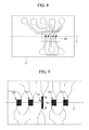
- FIG. 8 is a plan view of the sensor substrate shown in FIG. 5A as viewed from a detection surface.
- FIG. 9 is a partial enlarged view of a portion III of the sensor substrate shown in FIG. 8 .
- a flow meter 100 according to an embodiment of the present disclosure will be described below with reference to the drawings.
- the flow meter 100 of the embodiment is a time-of-flight type flow meter that heats liquid circulated in an internal flow passage and measures the flow rate of the liquid based on a time required for heated liquid to travel.
- the flow meter 100 of the embodiment is suitable for, for example, measuring a very small amount of flow rate of 0.06 mL/min to 3 mL/min.
- the flow meter 100 of the embodiment includes a sensor portion 10 , a control substrate 20 , a relay substrate 30 , an upper case 40 , and a bottom case 50 .
- the sensor portion 10 measures the flow rate of liquid that enters from an inlet 10 a , which is connected to an external pipe (not shown), exits from an outlet 10 b , which is connected to an external pipe (not shown), and is circulated in an internal flow passage 10 c.
- the sensor portion 10 detects the temperature of the liquid heated by a heating resistance wire 12 a (heating resistance element) shown in FIG. 9 , which is described below, by using temperature detecting resistance wires 12 b and 12 c (temperature detecting resistance element) shown in FIG. 9 , and transmits a temperature detecting signal indicating the detected temperature to the control substrate 20 through a signal line (not shown). Further, the sensor portion 10 detects the temperature of the liquid heated by the heating resistance wire 12 a by using temperature correcting resistance wires 12 e and 12 f shown in FIG. 9 , and transmits a temperature correcting signal indicating the detected temperature to the control substrate 20 through a signal line (not shown).
- the sensor portion 10 will be described in detail below.
- the control substrate 20 transmits a voltage signal to the heating resistance wire 12 a of the sensor portion 10 and heats the heating resistance wire 12 a . Further, the control substrate 20 is a device that calculates the flow rate of the liquid based on the temperature detecting signals transmitted from the temperature detecting resistance wires 12 b and 12 c and the temperature correcting signals transmitted from the temperature correcting resistance wires 12 e and 12 f.
- the relay substrate 30 is a substrate that performs a relay for transmitting and receiving various signals between the control substrate 20 and an external device (not shown).
- the relay substrate 30 is connected with a cable 200 for transmitting various signals to the external device (not shown) and receiving various signals from the external device.
- the upper case 40 is a member serving as an upper housing of the flow meter 100 , and houses the control substrate 20 therein.
- the bottom case 50 is a member serving as a lower housing of the flow meter 100 , and houses the sensor portion 10 therein.
- a stopper 60 is inserted between the bottom case 50 and the sensor portion 10 from a side of the sensor portion 10 that is closer to the inlet 10 a in a state where the sensor portion 10 is inserted in the bottom case 50 .
- a stopper 70 is inserted between the bottom case 50 and the sensor portion 10 from a side of the sensor portion 10 that is closer to the outlet 10 b in the state where the sensor portion 10 is inserted in the bottom case 50 .
- the sensor portion 10 is fixed to the bottom case 50 by the stoppers 60 and 70 .
- a fastening hole 50 a and a fastening hole 50 b are formed in the bottom surface of the bottom case 50 , and the bottom case is fixed to an installation surface (not shown) with fastening bolts (not shown) that are inserted from below the installation surface.
- the sensor portion 10 includes a measurement tube 11 , a sensor substrate (temperature detecting substrate) 12 , nuts 15 , an inlet-side body 16 , an outlet-side body 17 , an inlet-side ferrule 18 , and an outlet-side ferrule 19 .
- the measurement tube 11 is a tube having an inlet 11 a through which liquid enters and an outlet 11 b through which liquid flowing from the inlet 11 a exits. As shown in FIG. 6 (a cross-sectional view taken along the line I-I in FIG. 3 ), the measurement tube 11 is provided with the internal flow passage 10 c having a circular cross section and extending along an axis X.
- the measurement tube 11 is formed of glass (e.g., quartz glass in which the content of silicon dioxide is 100%, or other glass containing components other than silicon dioxide).
- the sensor substrate 12 is a substrate formed of glass (e.g., quartz glass in which the content of silicon dioxide is 100%, or other glass containing components other than silicon dioxide) obtained by forming the temperature correcting resistance wire 12 e , the temperature correcting resistance wire 12 f , the heating resistance wire (heating resistance element) 12 a , the temperature detecting resistance wire (temperature detecting resistance element) 12 b , and the temperature detecting resistance wire (temperature detecting resistance element) 12 c on a detection surface 12 d (shown in FIG. 5B ) along the axis X.
- glass e.g., quartz glass in which the content of silicon dioxide is 100%, or other glass containing components other than silicon dioxide
- the temperature correcting resistance wire 12 e , the temperature correcting resistance wire 12 f , the heating resistance wire 12 a , the temperature detecting resistance wire 12 b , and the temperature detecting resistance wire 12 c are each formed by depositing a metal film, such as platinum, on a substrate made of glass.
- a metal film such as platinum
- Each resistance wire is linearly formed with a constant width, and extends in the direction orthogonal to the axis X.
- Each resistance wire is turned back at an end portion thereof in the direction orthogonal to the axis X.
- the liquid circulated in the measurement tube 11 flows along the axis X from left to right in FIGS. 8 and 9 . Accordingly, when the heating resistance wire 12 a is instantaneously heated, the heated liquid flows from left to right along the axis X, reaches the position of the temperature detecting resistance wire 12 b , and then reaches the position of the temperature detecting resistance wire 12 c.
- control substrate 20 can calculate the circulation speed of the liquid circulated in the measurement tube 11 based on a timing when the heating resistance wire 12 a is instantaneously heated and a timing when the temperature detecting resistance wire 12 b and the temperature detecting resistance wire 12 c thereafter detect the temperature of the heated liquid. Further, the control substrate 20 can calculate the flow rate of the liquid based on the calculated circulation speed and the cross sectional area of the measurement tube 11 .
- control substrate 20 corrects the temperature detecting signal output from the temperature detecting resistance wire 12 b by using the temperature correcting signal output from the temperature correcting resistance wire 12 f .
- a part of the heat from the heating resistance wire 12 a is transmitted to the liquid through the measurement tube 11 , and the other part of the heat is directly transmitted to the temperature detecting resistance wire 12 b from the measurement tube 11 .
- the quantity of heat directly transmitted from the measurement tube 11 to the temperature detecting resistance wire 12 b is larger than the quantity of heat indirectly transmitted from the measurement tube 11 to the temperature detecting resistance wire 12 b through the liquid.
- the control substrate 20 uses the temperature correcting signal output from the temperature correcting resistance wire 12 f to correct the quantity of heat directly transmitted from the measurement tube 11 to the temperature detecting resistance wire 12 b .
- the distance from the temperature correcting resistance wire 12 f to the heating resistance wire 12 a in the direction of the axis X is equal to the distance from the temperature detecting resistance wire 12 b to the heating resistance wire 12 a in the direction of the axis X.
- the control substrate 20 subtracts the temperature correcting signal detected by the temperature correcting resistance wire 12 f from the temperature detecting signal detected by the temperature detecting resistance wire 12 b , thereby obtaining the quantity of heat indirectly transmitted from the measurement tube 11 to the temperature detecting resistance wire 12 b through the liquid.
- the control substrate 20 corrects the temperature detecting signal output from the temperature detecting resistance wire 12 b by using the temperature correcting signal output from the temperature correcting resistance wire 12 f .
- the control substrate 20 corrects the temperature detecting signal output from the temperature detecting resistance wire 12 c by using the temperature correcting signal output from the temperature correcting resistance wire 12 e .
- the distance from the temperature correcting resistance wire 12 e to the heating resistance wire 12 a in the direction of the axis X is equal to the distance from the temperature detecting resistance wire 12 c to the heating resistance wire 12 a in the direction of the axis X.
- control substrate 20 subtracts the temperature correcting signal detected by the temperature correcting resistance wire 12 e from the temperature detecting signal detected by the temperature detecting resistance wire 12 c , thereby obtaining the quantity of heat indirectly transmitted from the measurement tube 11 to the temperature detecting resistance wire 12 c through the liquid.
- the outer circumferential surface of the measurement tube 11 is provided with a flat surface 11 c on which the detection surface 12 d of the sensor substrate 12 is oppositely arranged.
- the outer circumferential surface of the measurement tube 11 is provided with a first recess 11 e and a second recess 11 f which are arranged so as to sandwich the internal flow passage 10 c at a position P 1 where the heating resistance wire 12 a is arranged on the axis X.
- the first recess 11 e and the second recess 11 f are provided so as to increase the quantity of heat transmitted from the heating resistance wire 12 a to the liquid through the measurement tube 11 .
- the outer circumferential surface of the measurement tube 11 has a circular cross section in a plane orthogonal to the axis X at a position where the sensor substrate 12 is not bonded.
- the flat surface 11 c of the measurement tube 11 is arranged as opposed to the detection surface 12 d of the sensor substrate 12 .
- the flat surface 11 c and the detection surface 12 d are bonded together with an adhesive.
- epoxy resin-based adhesive for example, epoxy resin-based adhesive, UV curable resin-based adhesive, thermosetting resin-based adhesive (thermosetting adhesive), and low-melting glass can be used.
- a bonding area A shown in FIG. 5C indicates an area where the flat surface 11 c and the detection surface 12 d are bonded together.
- the bonding area A is a planar area having a width in the direction orthogonal to the axis X.
- the bonding area A includes a first bonding area A 1 corresponding to a portion (first portion) on the axis X where the first recess 11 e and the second recess 11 f are arranged, and a second bonding area A 2 and a third bonding area A 3 which correspond to a portion (second portion) on the axis X where the first recess 11 e and the second recess 11 f are not arranged.
- a width W 1 of the first bonding area A 1 is narrower than a width W 2 of the second bonding area A 2 and the third bonding area A 3 .
- a distance D 1 (first distance) from the detection surface 12 d of the sensor substrate 12 to an inner circumferential surface 10 d of the internal flow passage 10 c is shorter than a distance D 2 (second distance) from a top portion 11 d of the measurement tube 11 to the inner circumferential surface 10 d of the internal flow passage 10 c .
- This is intended to reduce the distance D 1 from the detection surface 12 d of the sensor substrate 12 to the inner circumferential surface 10 d of the internal flow passage 10 c so as to improve the conductivity of heat form the heating resistance wire 12 a to the liquid and improve the temperature detection characteristics of the temperature detecting resistance wires 12 b and 12 c and the temperature correcting resistance wires 12 e and 12 f.
- an inner diameter ID of the internal flow passage 10 c matches a width W 3 of the heating resistance wire 12 a in a cross section orthogonal to the axis X.
- the inner diameter ID of the internal flow passage 10 c may be any diameter that is equal to or less than 1.5 times the width W 3 of the heating resistance wire 12 a in the cross section orthogonal to the axis X.
- the inner diameter ID of the internal flow passage 10 c is preferably, for example, equal to or greater than 0.5 mm, to allow the fluid having a flow rate of 0.06 mL/min to 3 mL/min to be circulated.
- the inner diameter ID of the internal flow passage 10 c is equal to or less than 1.5 times the width W 3 of the heating resistance wire 12 a , the inner diameter ID of the internal flow passage 10 c is relatively small, and thus a part of the heat from the heating resistance wire 12 a is not transmitted to the liquid, and the liquid is likely to be transmitted to the measurement tube 11 itself, or to the outside of the measurement tube 11 .
- the formation of the first recess 11 e and the second recess 11 f on the outer circumferential surface of the measurement tube 11 makes it possible to increase the quantity of heat transmitted from the heating resistance wire 12 a to the liquid circulated in the measurement tube 11 .
- the first recess 11 e and the second recess 11 f are formed of a first plane 11 g and a second plane 11 h , respectively, which are arranged so as to sandwich the internal flow passage 10 c .
- An angle ⁇ formed by the first plane 11 g and the flat surface 11 c and an angle ⁇ formed by the second plane 11 h and the flat surface 11 c are each a right angle.
- the pair of recesses 11 e and 11 f is formed of the first plane 11 g and the second plane 11 h , respectively, which are arranged in parallel with each other so as to sandwich the internal flow passage 10 c and which form a right angle with the flat surface 11 c , so that the quantity of heat transmitted from the heating resistance wire 12 a to the liquid circulated in the measurement tube 11 can be increased.
- a distance D 3 from the first plane 11 g to the second plane 11 h matches the width W 1 of the first bonding area A 1 .
- the distance D 3 is preferably equal to or less than 3 times the width W 3 of the heating resistance wire 12 a .
- the distance D 3 from the first plane 11 g to the second plane 11 h is preferably equal to or less than twice the inner diameter ID of the internal flow passage 10 c .
- the angle ⁇ formed between the first plane 11 g and the flat surface 11 c , and the angle ⁇ formed between the second plane 11 h and the flat surface 11 c are each a right angle.
- the present disclosure may include another aspect.
- the angle ⁇ formed between the first plane 11 g and the flat surface 11 c , and the angle ⁇ formed between the second plane 11 h and the flat surface 11 c may be set to any angle that is larger than 30 degrees and smaller than 150 degrees.
- the angle ⁇ As the angle ⁇ is decreased, the area of the first recess 11 e and the second recess 11 f increases. Accordingly, the quantity of heat transmitted from the heating resistance wire 12 a to the measurement tube 11 itself, or to the outside of the measurement tube 11 can be reduced. However, if the angle ⁇ is extremely reduced, the strength of the measurement tube 11 is decreased. Accordingly, it is preferable to set the angle ⁇ so that the distance from the internal flow passage 10 c to the outer circumferential surface of the measurement tube 11 to a desired distance or longer.
- the area of the first recess 11 e and the second recess 11 f is narrowed, but the width W 1 of the first bonding area A 1 is constant. Accordingly, the quantity of heat transmitted from the heating resistance wire 12 a to the liquid through the measurement tube 11 can be increased as compared with a case where the first recess 11 e and the second recess 11 f are not provided.
- the distance L 1 from the inlet 11 a of the measurement tube 11 to the position P 1 where the heating resistance wire 12 a is arranged on the axis X is longer than the distance L 2 from the outlet 11 b of the measurement tube 11 to the position P 1 .
- the heating resistance wire 12 a is arranged at the position P 1 on the downstream side in the liquid circulation direction from a midpoint of a line leading from the inlet 11 a to the outlet 11 b.
- the flow of the liquid can be stabilized until the liquid reaches the heating resistance wire 12 a even when turbulence occurs in the flow of the liquid in the connecting flow passage 16 a and the inlet 11 a of the measurement tube 11 .
- the position P 1 where the heating resistance wire 12 a is arranged is located at a midpoint of a line leading from an end portion P 2 , which faces the inlet 11 a , of the portion (first portion) on the axis X where the first recess 11 e and the second recess 11 f are arranged to an end portion P 3 facing the outlet 11 b.
- the end portion P 2 and the end portion P 3 are provided at equal distances from the heating resistance wire 12 a , so that the quantity of heat transmitted from the heating resistance wire 12 a to the measurement tube 11 on the upstream side of the heating resistance wire 12 a can be made equal to the quantity of heat transmitted from the heating resistance wire 12 a to the measurement tube 11 on the downstream side of the heating resistance wire 12 a.
- the nuts 15 include the inlet-side nut 15 a attached to the inlet-side body 16 and the outlet-side nut 15 b attached to the outlet-side body 17 .
- the inlet-side nut 15 a is a cylindrical member fitted along the outer circumferential surface of the measurement tube 11 to be closer to the outlet 11 b than the inlet-side body 16 .
- the inlet-side nut 15 a has internal threads 15 g on an inner circumferential surface of its end portion facing the inlet 10 a .
- the outlet-side nut 15 b is a cylindrical member fitted along the outer circumferential surface of the measurement tube 11 to be closer to the inlet 11 a than the outlet-side body 17 .
- the outlet-side nut 15 b has internal threads 15 h on an inner circumferential surface of its end portion facing the outlet 10 b.
- the inlet-side nut 15 a is attached to the inlet-side body 16 as the internal threads 15 g of the inlet-side nut 15 a and the external threads 16 b of the inlet-side body 16 are fastened together.
- the outlet-side nut 15 b is attached to the outlet-side body 17 as the internal threads 15 h of the outlet-side nut 15 b and the external threads 17 b of the outlet-side body 17 are fastened together.
- the inlet-side nut 15 a has the recess 15 e (the first recess) that is recessed toward the inlet 10 a , at its end portion facing the outlet 10 b .
- the recess 15 e is filled with the filler 15 i .
- the inlet 11 a side end portion of the sensor substrate 12 and the inlet 11 a side end portion of the reinforcing plate 13 are fixed to the inlet-side nut 15 a by the filler 15 i.
- the outlet-side nut 15 b has the recess 15 f (the second recess) that is recessed toward the outlet 10 b , at its end portion facing the inlet 10 a .
- the recess 15 f is filled with the filler 15 j .
- the outlet 11 b side end portion of the sensor substrate 12 and the outlet 11 b side end portion of the reinforcing plate 13 are fixed to the outlet-side nut 15 b by the filler 15 j.
- the inlet-side body 16 is a member in which the inlet 11 a of the measurement tube 11 is inserted and the connecting flow passage 16 a having a circular cross section is formed.
- An external thread 16 b is formed on the outer circumferential surface at an end portion of the inlet-side body 16 facing the outlet 10 b.
- the outlet-side body 17 is a member in which the outlet 11 b of the measurement tube 11 is inserted and a connecting flow passage 17 a having a circular cross section is formed.
- An external thread 17 b is formed on the outer circumferential surface at an end portion of the outlet-side body 17 facing the inlet 10 a.
- the inlet-side body 16 and the outlet-side body 17 are each formed of a resin material (e.g., PTFE: polytetrafluoroethylene) having a high corrosion resistance.
- PTFE polytetrafluoroethylene
- the inlet-side ferrule 18 is a cylindrical resin member (e.g., formed of PTFE) that is inserted in between the outer circumferential surface of the measurement tube 11 and the inner circumferential surface of the outlet 10 b side end portion of the inlet-side body 16 .
- an inlet 10 a side end portion of the inlet-side ferrule 18 has a tip portion 18 a at which the distance between an inner circumferential surface and an outer circumferential surface of the tip portion 18 a gradually decreases toward the inlet 10 a .
- the tip portion 18 a is inserted into a groove portion 16 c formed inside the inlet-side body 16 as it is inserted into the inlet-side body 16 .
- the outlet-side ferrule 19 is a cylindrical resin member (e.g., formed of PTFE) that is inserted in between the outer circumferential surface of the measurement tube 11 and an inner circumferential surface of the inlet 10 a side end portion of the outlet-side body 17 .
- an outlet 10 b side end portion of the outlet-side ferrule 19 has a tip portion 19 a at which the distance between an inner circumferential surface and an outer circumferential surface gradually decreases toward the outlet 10 b .
- the tip portion 19 a is inserted into a groove portion 17 c formed inside the outlet-side body 17 as it is inserted into the outlet-side body 17 .
- the sensor unit 10 in the flow meter 100 of the embodiment is assembled by fastening the internal threads 15 g of the inlet-side nut 15 a to the external threads 16 b of the inlet-side body 16 with the inlet 11 a of the measurement tube 11 and the inlet-side ferrule 18 inserted in the outlet 10 b side end portion of the inlet-side body 16 , and fastening the internal threads 15 h of the outlet-side nut 15 b to the external threads 17 b of the outlet-side body 17 with the outlet 11 b of the measurement tube 11 and the outlet-side ferrule 19 inserted in the inlet 10 a side end portion of the outlet-side body 17 .
- the tip portion 18 a of the inlet-side ferrule 18 is forced into the groove portion 16 c of the inlet-side body 16 as the internal threads 15 g of the inlet-side nut 15 a become fastened to the external threads 16 b of the inlet-side body 16 . Because the groove portion 16 c is sharper than the tip portion 18 a , the tip portion 18 a is gradually deformed as it is forced into the groove portion 16 c , and finally, deformed to be accommodated in the groove portion 16 c without leaving any space.
- the deformation of the tip portion 18 a forms a seal area between the outer circumferential surface of the measurement tube 11 and the inner circumferential surface of the inlet-side body 16 , which reliably shuts off liquid that flows out through a location of connection of the connection flow passage 16 a with the internal flow passage 10 c so that the liquid never leaks to the outside.
- the tip portion 18 a of the inlet-side ferrule 18 is positioned in the vicinity of the location of connection of the connection flow passage 16 a with the internal flow passage 10 c , thereby reducing an amount of liquid that flows out through the connection location to be remained (dead volume).
- the inlet-side body 16 and the measurement tube 11 are connected such that they are arranged with their central axes coincident on the axis X.
- the connection structure enables the inlet-side body 16 and the measurement tube 11 to be joined together without any steps between their inner walls, so that the flow of the liquid flowing inside will never be turbulent. Accordingly, the sensor substrate 12 can stably measure the flow rate of the liquid.
- the fastening of the internal threads 15 g of the inlet-side nut 15 a and the external threads 16 b of the inlet-side body 16 is completed as an inlet 10 a side end of the inlet-side nut 15 a comes into contact with a projecting portion 16 d of the inlet-side body 16 .
- the amount of deformation of the tip portion 18 a forced into the groove portion 16 c can be kept appropriate by arranging the projecting portion 16 d at an appropriate position.
- the tip portion 19 a of the outlet-side ferrule 19 is forced into the groove portion 17 c of the outlet-side body 17 as the internal threads 15 h of the outlet-side nut 15 b become fastened to the external threads 17 b of the outlet-side body 17 . Because the groove portion 17 c is sharper than the tip portion 19 a , the tip portion 19 a is gradually deformed as it is forced into the groove portion 17 c , and finally, deformed to be accommodated in the groove portion 17 c without leaving any space.
- the deformation of the tip portion 19 a forms a seal area between the outer circumferential surface of the measurement tube 11 and the inner circumferential surface of the outlet-side body 17 , which reliably shuts off liquid that flows out through a location of connection of the connection flow passage 17 a with the internal flow passage 10 c so that the liquid never leaks to the outside.
- the tip portion 19 a of the outlet-side ferrule 19 is positioned in the vicinity of the location of connection of the connection flow passage 17 a with the internal flow passage 10 c , thereby reducing an amount of liquid that flows out through the connection location to be remained (dead volume).
- the fastening of the internal threads 15 h of the outlet-side nut 15 b and the external threads 17 b of the outlet-side body 17 is completed as an outlet 10 b side end of the outlet-side nut 15 b comes into contact with a projecting portion 17 d of the outlet-side body 17 .
- the amount of deformation of the tip portion 19 a forced into the groove portion 17 c can be kept appropriate by arranging the projecting portion 17 d at an appropriate position.
- the flat surface 11 c formed on the outer circumferential surface of the cylindrical measurement tube 11 is bonded to the detection surface 12 d of the sensor substrate 12 where the heating resistance wire 12 a and the temperature detecting resistance wires 12 b and 12 c are formed, thereby forming the planar bonding area A having a width in the direction orthogonal to the axis X.
- the pair of recesses (the first recess 11 e and the second recess 11 f ) is formed so as to sandwich the internal flow passage 10 c at the position P 1 where the heating resistance wire 12 a is arranged on the axis X.
- the width W 1 of the bonding area A in the first portion on the axis X where the pair of recesses is arranged is narrower than the width W 2 of the bonding area A in the second portion on the axis X where the pair of recesses is not arranged.
- the width of the bonding area A is narrowed by the pair of recesses, so that the quantity of heat transmitted from the heating resistance wire 12 a to the liquid through the measurement tube 11 is increased as compared with a case where the pair of recesses is not provided.
- the width of the bonding area A is secured, so that the sensor substrate 12 and the measurement tube 11 can be securely bonded and fixed.
- the quantity of heat transmitted from the heating resistance wire 12 a to the liquid circulated in the measurement tube 11 can be increased.
- the sensor substrate 12 and the measurement tube 11 are made of glass.
- the flow rate measurement accuracy can be maintained regardless of changes in temperature.
- the materials with the same thermal conductivity properties are bonded together, the adhesiveness of the sensor substrate 12 to the measurement tube 11 can be maintained regardless of changes in temperature.
- the measurement tube 11 is made of glass.
- the present disclosure may include another aspect.
- the measurement tube 11 may be formed of a resin material (e.g., polycarbonate) having workability and heat resistance. The use of the resin material makes it possible to easily form the first recess 11 e and the second recess 11 f on the measurement tube 11 .
Landscapes
- Physics & Mathematics (AREA)
- General Physics & Mathematics (AREA)
- Fluid Mechanics (AREA)
- Engineering & Computer Science (AREA)
- Aviation & Aerospace Engineering (AREA)
- Measuring Volume Flow (AREA)
Abstract
Description
Claims (6)
Applications Claiming Priority (2)
| Application Number | Priority Date | Filing Date | Title |
|---|---|---|---|
| JP2016204264A JP6692732B2 (en) | 2016-10-18 | 2016-10-18 | Flowmeter |
| JP2016-204264 | 2016-10-18 |
Publications (2)
| Publication Number | Publication Date |
|---|---|
| US20180106826A1 US20180106826A1 (en) | 2018-04-19 |
| US10473682B2 true US10473682B2 (en) | 2019-11-12 |
Family
ID=60080696
Family Applications (1)
| Application Number | Title | Priority Date | Filing Date |
|---|---|---|---|
| US15/782,215 Active 2038-01-31 US10473682B2 (en) | 2016-10-18 | 2017-10-12 | Flow meter including increased measuring detection accuracy |
Country Status (3)
| Country | Link |
|---|---|
| US (1) | US10473682B2 (en) |
| EP (1) | EP3312570B1 (en) |
| JP (1) | JP6692732B2 (en) |
Citations (8)
| Publication number | Priority date | Publication date | Assignee | Title |
|---|---|---|---|---|
| US3992043A (en) * | 1975-01-16 | 1976-11-16 | E. I. Du Pont De Nemours And Company | Tube fitting |
| US6208254B1 (en) * | 1999-09-15 | 2001-03-27 | Fluid Components Intl | Thermal dispersion mass flow rate and liquid level switch/transmitter |
| US20030049877A1 (en) * | 2000-05-04 | 2003-03-13 | Felix Mayer | Flow sensor |
| EP1365216A1 (en) | 2002-05-10 | 2003-11-26 | Yamatake Corporation | Flow sensor and method of manufacturing the same |
| US20050022594A1 (en) * | 1998-12-07 | 2005-02-03 | Aravind Padmanabhan | Flow sensor with self-aligned flow channel |
| JP2006010322A (en) | 2004-06-22 | 2006-01-12 | Yokogawa Electric Corp | Thermal flow meter |
| EP3059557A1 (en) * | 2015-02-23 | 2016-08-24 | Surpass Industry Co., Ltd. | Thermal flow meter |
| US20160245682A1 (en) * | 2015-02-23 | 2016-08-25 | Surpass Industry Co., Ltd. | Thermal flow meter and method of manufacturing the same |
Family Cites Families (4)
| Publication number | Priority date | Publication date | Assignee | Title |
|---|---|---|---|---|
| JP2012154712A (en) * | 2011-01-25 | 2012-08-16 | Tokyo Electron Ltd | Flow sensor and resist application device using the same |
| JP2012204813A (en) * | 2011-03-28 | 2012-10-22 | Tokyo Electron Ltd | Bubble detection method, resist application method, and resist application device |
| JP2012202971A (en) * | 2011-03-28 | 2012-10-22 | Tokyo Electron Ltd | Flow sensor and resist coating device using the same |
| JP6535604B2 (en) * | 2016-01-06 | 2019-06-26 | アズビル株式会社 | Measuring device and manufacturing method of measuring device |
-
2016
- 2016-10-18 JP JP2016204264A patent/JP6692732B2/en active Active
-
2017
- 2017-10-11 EP EP17195910.9A patent/EP3312570B1/en active Active
- 2017-10-12 US US15/782,215 patent/US10473682B2/en active Active
Patent Citations (11)
| Publication number | Priority date | Publication date | Assignee | Title |
|---|---|---|---|---|
| US3992043A (en) * | 1975-01-16 | 1976-11-16 | E. I. Du Pont De Nemours And Company | Tube fitting |
| US20050022594A1 (en) * | 1998-12-07 | 2005-02-03 | Aravind Padmanabhan | Flow sensor with self-aligned flow channel |
| US6208254B1 (en) * | 1999-09-15 | 2001-03-27 | Fluid Components Intl | Thermal dispersion mass flow rate and liquid level switch/transmitter |
| US20020130780A1 (en) | 1999-09-15 | 2002-09-19 | Mcqueen Malcolm M. | Thermal dispersion mass flow rate and liquid level switch/transmitter |
| US20030049877A1 (en) * | 2000-05-04 | 2003-03-13 | Felix Mayer | Flow sensor |
| EP1365216A1 (en) | 2002-05-10 | 2003-11-26 | Yamatake Corporation | Flow sensor and method of manufacturing the same |
| US20040025585A1 (en) * | 2002-05-10 | 2004-02-12 | Koji Seki | Flow sensor and method of manufacturing the same |
| JP2006010322A (en) | 2004-06-22 | 2006-01-12 | Yokogawa Electric Corp | Thermal flow meter |
| EP3059557A1 (en) * | 2015-02-23 | 2016-08-24 | Surpass Industry Co., Ltd. | Thermal flow meter |
| US20160245683A1 (en) * | 2015-02-23 | 2016-08-25 | Surpass Industry Co., Ltd. | Thermal flow meter |
| US20160245682A1 (en) * | 2015-02-23 | 2016-08-25 | Surpass Industry Co., Ltd. | Thermal flow meter and method of manufacturing the same |
Non-Patent Citations (2)
| Title |
|---|
| Foreign Communication from a related application-Extended European Search Report of EP Application No. 17195910.9, dated Mar. 8, 2018, 8 pages. |
| Foreign Communication from a related application—Extended European Search Report of EP Application No. 17195910.9, dated Mar. 8, 2018, 8 pages. |
Also Published As
| Publication number | Publication date |
|---|---|
| JP2018066602A (en) | 2018-04-26 |
| EP3312570B1 (en) | 2019-06-19 |
| EP3312570A1 (en) | 2018-04-25 |
| US20180106826A1 (en) | 2018-04-19 |
| JP6692732B2 (en) | 2020-05-13 |
Similar Documents
| Publication | Publication Date | Title |
|---|---|---|
| US9581480B2 (en) | Micro flow sensor | |
| KR101424783B1 (en) | Pressure sensor, differential pressure flow meter and flow controller | |
| US20100193051A1 (en) | Differential-pressure flowmeter and flow-rate controller | |
| US8069734B2 (en) | Multi-vortex flowmeter integrating pressure gauge | |
| US10024704B2 (en) | Thermal flow meter having seal areas with deformed ferrules | |
| JP6563211B2 (en) | Thermal flow meter and manufacturing method thereof | |
| JP2006029966A (en) | Multi-vortex flowmeter | |
| US10473682B2 (en) | Flow meter including increased measuring detection accuracy | |
| US11512991B2 (en) | Flow meter and method of manufacturing flow meter | |
| US11143536B2 (en) | Thermal flowmeter and method for determining weighting factor | |
| US20240027246A1 (en) | Thermal type flowmeter and manufacturing method of thermal type flowmeter | |
| JP2019082346A (en) | Thermal flowmeter | |
| JP2016065766A (en) | Microwave densitometer and measurement tube | |
| KR20220137349A (en) | Ultrasonic Flow Meter | |
| JPH08240463A (en) | Liquid flow meter | |
| TWM561196U (en) | Embedded sensing module and sensing device |
Legal Events
| Date | Code | Title | Description |
|---|---|---|---|
| FEPP | Fee payment procedure |
Free format text: ENTITY STATUS SET TO UNDISCOUNTED (ORIGINAL EVENT CODE: BIG.); ENTITY STATUS OF PATENT OWNER: SMALL ENTITY |
|
| AS | Assignment |
Owner name: SURPASS INDUSTRY CO. LTD., JAPAN Free format text: ASSIGNMENT OF ASSIGNORS INTEREST;ASSIGNORS:ABO, KAZUO;NAKAJIMA, KOJI;REEL/FRAME:043906/0468 Effective date: 20170928 |
|
| FEPP | Fee payment procedure |
Free format text: ENTITY STATUS SET TO SMALL (ORIGINAL EVENT CODE: SMAL); ENTITY STATUS OF PATENT OWNER: SMALL ENTITY |
|
| STPP | Information on status: patent application and granting procedure in general |
Free format text: DOCKETED NEW CASE - READY FOR EXAMINATION |
|
| STPP | Information on status: patent application and granting procedure in general |
Free format text: NON FINAL ACTION MAILED |
|
| STPP | Information on status: patent application and granting procedure in general |
Free format text: NOTICE OF ALLOWANCE MAILED -- APPLICATION RECEIVED IN OFFICE OF PUBLICATIONS |
|
| STPP | Information on status: patent application and granting procedure in general |
Free format text: PUBLICATIONS -- ISSUE FEE PAYMENT RECEIVED |
|
| STCF | Information on status: patent grant |
Free format text: PATENTED CASE |
|
| MAFP | Maintenance fee payment |
Free format text: PAYMENT OF MAINTENANCE FEE, 4TH YR, SMALL ENTITY (ORIGINAL EVENT CODE: M2551); ENTITY STATUS OF PATENT OWNER: SMALL ENTITY Year of fee payment: 4 |