US10472859B2 - Door mount mechanism for a smart lock system - Google Patents

Door mount mechanism for a smart lock system Download PDF

Info

Publication number
US10472859B2
US10472859B2 US15/117,139 US201515117139A US10472859B2 US 10472859 B2 US10472859 B2 US 10472859B2 US 201515117139 A US201515117139 A US 201515117139A US 10472859 B2 US10472859 B2 US 10472859B2
Authority
US
United States
Prior art keywords
coupling
door
coupling segment
mount mechanism
segment
Prior art date
Legal status (The legal status is an assumption and is not a legal conclusion. Google has not performed a legal analysis and makes no representation as to the accuracy of the status listed.)
Active, expires
Application number
US15/117,139
Other versions
US20170002585A1 (en
Inventor
Che-Ming KU
Current Assignee (The listed assignees may be inaccurate. Google has not performed a legal analysis and makes no representation or warranty as to the accuracy of the list.)
Candy House Inc
Original Assignee
Candy House Inc
Priority date (The priority date is an assumption and is not a legal conclusion. Google has not performed a legal analysis and makes no representation as to the accuracy of the date listed.)
Filing date
Publication date
Application filed by Candy House Inc filed Critical Candy House Inc
Priority to US15/117,139 priority Critical patent/US10472859B2/en
Assigned to CANDY HOUSE INC. reassignment CANDY HOUSE INC. ASSIGNMENT OF ASSIGNORS INTEREST (SEE DOCUMENT FOR DETAILS). Assignors: KU, CHE-MING
Publication of US20170002585A1 publication Critical patent/US20170002585A1/en
Application granted granted Critical
Publication of US10472859B2 publication Critical patent/US10472859B2/en
Active legal-status Critical Current
Adjusted expiration legal-status Critical

Links

Images

Classifications

    • EFIXED CONSTRUCTIONS
    • E05LOCKS; KEYS; WINDOW OR DOOR FITTINGS; SAFES
    • E05BLOCKS; ACCESSORIES THEREFOR; HANDCUFFS
    • E05B47/00Operating or controlling locks or other fastening devices by electric or magnetic means
    • E05B47/0001Operating or controlling locks or other fastening devices by electric or magnetic means with electric actuators; Constructional features thereof
    • E05B47/0012Operating or controlling locks or other fastening devices by electric or magnetic means with electric actuators; Constructional features thereof with rotary electromotors
    • EFIXED CONSTRUCTIONS
    • E05LOCKS; KEYS; WINDOW OR DOOR FITTINGS; SAFES
    • E05BLOCKS; ACCESSORIES THEREFOR; HANDCUFFS
    • E05B47/00Operating or controlling locks or other fastening devices by electric or magnetic means
    • E05B47/02Movement of the bolt by electromagnetic means; Adaptation of locks, latches, or parts thereof, for movement of the bolt by electromagnetic means
    • EFIXED CONSTRUCTIONS
    • E05LOCKS; KEYS; WINDOW OR DOOR FITTINGS; SAFES
    • E05BLOCKS; ACCESSORIES THEREFOR; HANDCUFFS
    • E05B47/00Operating or controlling locks or other fastening devices by electric or magnetic means
    • E05B2047/0084Key or electric means; Emergency release
    • EFIXED CONSTRUCTIONS
    • E05LOCKS; KEYS; WINDOW OR DOOR FITTINGS; SAFES
    • E05BLOCKS; ACCESSORIES THEREFOR; HANDCUFFS
    • E05B47/00Operating or controlling locks or other fastening devices by electric or magnetic means
    • E05B2047/0091Retrofittable electric locks, e.g. an electric module can be attached to an existing manual lock
    • EFIXED CONSTRUCTIONS
    • E05LOCKS; KEYS; WINDOW OR DOOR FITTINGS; SAFES
    • E05BLOCKS; ACCESSORIES THEREFOR; HANDCUFFS
    • E05B47/00Operating or controlling locks or other fastening devices by electric or magnetic means
    • E05B2047/0094Mechanical aspects of remotely controlled locks
    • E05B2047/0095Mechanical aspects of locks controlled by telephone signals, e.g. by mobile phones

Definitions

  • the disclosure relates to a door mount mechanism, more particularly to a door mount mechanism for a smart lock system.
  • a conventional smart lock generally includes a door mount that is adapted to be fitted onto a door lock, and that is controlled by a control system.
  • a disadvantage of the conventional smart lock is that the installation of the door mount is relatively complicated and time-consuming.
  • FIG. 1 illustrates a typical mechanical lock device 100 .
  • the typical mechanical lock device 100 includes a base plate 102 , and a thumb turn 104 connected rotatably to the base plate 102 .
  • the mechanical lock device 100 is mounted on a door 200 (see FIG. 2 ) with the base plate 102 being coupled to the door 200 at a position close to a handle 202 .
  • the mechanical lock device 100 has various configurations in terms of the shape of the thumb turn 104 , such as being elliptic (see FIG. 1 ), triangular (see FIG. 2 ) or round (see FIG. 3 ), and in terms of the location of the thumb turn 104 on the base plate 102 .
  • Another disadvantage of the conventional smart lock is that the door mount of the conventional smart lock may not be properly and quickly fitted onto the thumb turn 104 of different sizes and at locations of the typical mechanical lock device 100 .
  • the object of the disclosure is to provide a door mount mechanism for a smart lock system that can alleviate at least one of the drawbacks associated with the abovementioned prior art.
  • a door mount mechanism of the present disclosure is adapted for use in a smart lock system.
  • the door mount mechanism is adapted to be mounted onto a door for rotating a thumb turn of a door lock which is mounted on the door.
  • the door mount mechanism includes a casing, a rotatable component and an intermediate coupling.
  • the casing has a door-mounting end that is adapted for abutting against the door, and defines a receiving space that is adapted for receiving the door lock, and that has an opening at the door-mounting end and adapted for extension of the door lock therethrough.
  • the rotatable component is coupled rotatably to the casing.
  • the intermediate coupling includes a first coupling segment that is connected co-rotatably to the rotatable component, and a second coupling segment that is connected co-rotatably to and linearly movable relative to the first coupling segment and that is adapted for driving rotation of the thumb turn of the door lock such that the thumb turn is co-rotatable with the rotatable component.
  • FIG. 1 is a perspective view of a typical mechanical lock device
  • FIG. 2 is another perspective view of a variation of the typical mechanical lock device mounted on a door
  • FIG. 3 is a perspective view of another variation of the typical mechanical lock device and a door handle
  • FIG. 4 is a perspective view of a first embodiment of a door mount mechanism according to the disclosure.
  • FIG. 5 is a perspective view of a rotatable component and an actuating unit of the first embodiment
  • FIG. 6 is another perspective view of the rotatable component and the actuating unit of the first embodiment
  • FIG. 7 is a bottom view of an intermediate coupling of the first embodiment
  • FIG. 8 is a fragmentary perspective view of the intermediate coupling of the first embodiment
  • FIG. 9 is a view similar to FIG. 7 , but illustrating a second coupling segment being moved relative to a first coupling segment
  • FIG. 10 is an assembled perspective view of a modification of the second coupling segment
  • FIG. 11 is an exploded perspective view of the modification of the second coupling segment
  • FIG. 12 is an assembled perspective view of another modification of the second coupling segment
  • FIG. 13 is an exploded perspective view of the another modification of the second coupling segment
  • FIG. 14 is a sectional view of the another modification of the second coupling segment
  • FIG. 15 is an exploded perspective view of the intermediate coupling of a second embodiment of a door mount mechanism according to the disclosure.
  • FIG. 16 is an assembled perspective view of the intermediate coupling of the second embodiment
  • FIG. 17 is a sectional view of a variation of a first coupling segment and a third coupling segment of the intermediate coupling of the second embodiment
  • FIG. 18 is an exploded perspective view of a modification of the intermediate coupling of the second embodiment
  • FIG. 19 is an assembled perspective view of the modification of the intermediate coupling of the second embodiment.
  • FIG. 20 is a bottom view of the intermediate coupling of a third embodiment of a door mount mechanism according to the disclosure.
  • FIG. 21 a bottom view of the intermediate coupling of a fourth embodiment of a door mount mechanism according to the disclosure.
  • FIG. 22 is a schematic, fragmentary exploded perspective view illustrating a variation of the second coupling segment.
  • a first embodiment of a door mount mechanism is adapted for use in a smart lock system, and is adapted to be mounted onto a door (not shown) for rotating a thumb turn (not shown) of a door lock (not shown).
  • the door lock includes a base plate (not shown) which is mounted on the door and on which the thumb turn is rotatably disposed.
  • the door mount mechanism includes a casing 1 , a rotatable component 2 , an actuating unit 3 and an intermediate coupling 4 .
  • the casing 1 includes a base wall 11 , a surrounding wall 12 extending from a periphery of the base wall 11 and cooperating with the base wall 11 to define a receiving space 100 (see FIG. 7 ).
  • the base wall 11 is substantially square.
  • the surrounding wall 12 has a door-mounting end 121
  • the receiving space 100 has an opening 101 (see FIG. 7 ) at the door-mounting end 121 .
  • the base wall 11 is formed with a round hole 111 .
  • the rotatable component 2 is coupled rotatably to the casing 1 .
  • the rotatable component 2 has a base portion 21 engaging rotatably the round hole 111 of the casing 1 , and a knob portion 22 projecting from the base portion 21 away from the receiving space 100 and being accessible to a user.
  • the actuating unit 3 includes an actuating module 31 that includes a motor and a solenoid valve, and a gear set 32 that is driven rotatably by the motor of the actuating module 31 .
  • the actuating unit 3 is connected to a control circuit (not shown).
  • the control circuit receives commands from a user device, such as a mobile phone, and the actuating unit 3 is activated by signals received from the control circuit to operate to drive rotation of the rotatable component 2 .
  • the intermediate coupling 4 includes a first coupling segment 41 and a second coupling segment 42 .
  • the second coupling segment 42 is made from an elastic material, is configured as a hollow frame, and has two parallel side frame sections 421 and two parallel elongated slide grooves 422 (only one is shown in FIG. 8 ) respectively formed in the side frame sections 421 and facing away from each other.
  • the first coupling segment 41 has two subsegments 411 .
  • Each of the subsegments 411 is configured as a telescopic structure, and has a first end that is connected fixedly and co-rotatably to the rotatable component 2 , and a second end that is opposite to the first end and that engages slidably a respective one of the slide grooves 422 .
  • the subsegments 411 are collinearly arranged with each other and are perpendicular to the slide grooves 422 .
  • a distance between the first and second ends of each of the subsegments 411 is adjustable, and the second coupling segment 42 is connected co-rotatably to and is linearly movable relative to the first coupling segment 41 (see FIGS. 8 and 9 ).
  • the casing 1 is mounted onto the door with the door-mounting end 121 of the surrounding wall 12 abutting against the door and surrounding the base plate of the door lock, and with the door lock extending into the receiving space 100 through the opening 101 until the thumb turn of the door lock is surrounded by and inserted into the second coupling segment 42 .
  • the side frame sections 421 are deformable in a first direction in which the subsegments 411 extend.
  • the second coupling segment 42 is slidable relative to the first coupling segment 41 in a second direction perpendicular to the first direction. Therefore, the intermediate coupling 4 has a relatively great flexibility in terms of fitting onto the thumb turn of different sizes, shapes, or at various relative locations of the base plate. Therefore, when the actuating unit 3 is remotely controlled to actuate rotation of the rotatable component 2 , the thumb turn is rotated together with the rotatable component 2 . Moreover, with the knob portion 22 being accessible to the user, the rotatable component 2 can also be manually rotated.
  • FIGS. 10 and 11 illustrate a modification of the first embodiment, in which the second coupling segment 42 further has an extension section 423 that is coupled telescopically to the side frame sections 421 , and a plurality of resilient members 424 that are disposed between the side frame sections 421 and the extension section 423 , and that are located at corners of the extension section 423 for biasing the extension section 423 in a direction away from the side frame sections 421 . Therefore, the intermediate coupling 4 (see FIG. 7 ) is capable of firmly holding a relatively large thumb turn with a distal end of the extension section 423 abutting resiliently against a base plate on which the thumb turn is rotatably mounted.
  • FIGS. 12 to 14 illustrate another modification of the first embodiment, in which the extension section 423 is formed with a plurality of positioning slots 4231 , and the side frame sections 421 are formed with a plurality of positioning protrusions 4211 (only one is visible in FIG. 13 ).
  • the user can manually move the extension section 423 relative to the side frame sections 421 , and engage the positioning protrusions 4211 with corresponding ones of the positioning slots 4231 to position the extension section 423 at a desired position relative to the side frame sections 421 .
  • the second embodiment of a door mount mechanism according to the present disclosure differs from the first embodiment in the configuration of the intermediate coupling 4 .
  • the intermediate coupling 4 further includes a third coupling segment 43 interposed between the first and second coupling segments 41 , 42 .
  • the intermediate coupling 4 is configured as an oldham coupling.
  • the first coupling segment 41 has a plate section 4101 that is formed with an elongated groove 4102 , and an engaging section 4103 that projects at a side opposite to the elongated groove 4102 to be connected co-rotatably to the rotatable component 2 (see FIG. 4 ).
  • the third coupling segment 43 has a surface that faces the first coupling segment 41 and an elongated tongue 4301 that is formed on the surface and that fittingly and slidably engages the elongated groove 4102 .
  • the second and third coupling segments 42 , 43 are coupled together via a similar tongue-and-groove mechanism, but the elongated tongue and groove provided between the second third coupling segments 42 , 43 are perpendicular to those provided between the first and third coupling segments 41 , 43 .
  • each of the coupling heads has a main body 4201 which is formed with a cavity 4202 of a specific shape adapted to be fitted with a thumb turn having the same shape.
  • a thumb turn shaped substantially rectangular
  • one of the coupling heads with the cavity 4202 being formed to be substantially rectangular is chosen to fit onto the thumb turn.
  • the elongated groove 4102 is formed only in the plate section 4101 in this embodiment, the elongated groove 4102 may be formed through the plate section 4101 into the engaging section 4103 in other embodiments (see FIG. 17 ), so that the thickness of the plate section 4101 can be decreased, thereby miniaturizing the intermediate coupling 4 .
  • the third embodiment of a door mount mechanism according to the present disclosure differs from the previous embodiments in the configuration of the intermediate coupling 4 .
  • the third coupling segment 43 is larger than and surrounds the second coupling segment 42 .
  • the second coupling segment 42 has opposite edges coupled slidably and respectively to the third coupling segment 43 via tongue-and-groove mechanisms.
  • the first coupling segment 41 is larger than and surrounds the third coupling segment 43
  • the third coupling segment 43 has opposite edges coupled slidably and respectively to the first coupling segment 41 via tongue-and-groove mechanisms (which are not co-rotatable with the first coupling segment 41 ), such that the second coupling segment 42 is movable relative to the first coupling segment 41 in a first direction, and is movable relative to the first coupling segment 41 via the third coupling segment 43 in a second direction perpendicular to the first direction.
  • the second coupling segment 42 has a rigid outer part 428 coupled slidably to the third coupling segment 43 , and a rotatable inner part 427 surrounded by the rigid outer part 428 , formed with a cavity 4271 that is adapted to receive the thumb turn of the door lock, and made from an elastic material so that the second coupling segment 42 can fit on thumb turns of different shapes and sizes.
  • the fourth embodiment of a door mount mechanism according to the present disclosure differs from the previous embodiments in the configuration of the intermediate coupling 4 .
  • the first coupling segment 41 has two subsegments 411 ′ connected to a periphery of the rotatable component 2 (see FIG. 4 ).
  • Each of the subsegments 411 ′ has opposite first and second ends.
  • the first ends of the subsegments 411 ′ are aligned with each other in a first direction
  • the second ends of the subsegments 411 ′ are aligned with each other in the first direction.
  • the second coupling segment 42 has a main subsegment 421 ′ adapted for surrounding the thumb turn of the door lock, and four coupling subsegments 423 .
  • Two of the coupling subsegments 423 are connected to an end of the main subsegment 421 ′ and are connected slidably and respectively to the first and second ends of one of the subsegments 411 ′.
  • the other two of the coupling segments 423 are connected to an opposite end of the main subsegment 421 ′ and are connected slidably and respectively to the first and second ends of the other one of the subsegments 411 ′.
  • the second coupling segment 42 is movable relative to the first coupling segment 41 in the first direction.
  • the main subsegment 421 ′ has a width in a second direction perpendicular to the first direction and adapted to be larger than that of the thumb turn.
  • the main subsegment 421 ′ would be allowed to be movable relative to the thumb turn in the second direction to thereby properly dri ye rotation of the thumb turn.
  • the second coupling segment 42 may be configured to have a base board 420 and a driving bar 425 projecting co-rotatably from the base board 420 and eccentrically disposed on the base board 420 .
  • the second coupling segment 42 is adapted to push the thumb turn 90 of the door lock to rotate using the driving bar 425 and there is no need for any part of the second coupling segment 42 to be elastic and deformable.
  • the door mount mechanism according to the present disclosure may also be used for rotating a knob of a switch mechanism, such as a switch knob of a washing machine, an oven, and so on.

Abstract

A door mount mechanism is to be mounted onto a door for rotating a thumb turn of a door lock. The door mount mechanism includes a casing, a rotatable component and an intermediate coupling. The casing is for abutting against the door, and defines a receiving space that is adapted for receiving the door lock. The rotatable component is coupled rotatably to the casing. The intermediate coupling includes a first coupling segment connected co-rotatably to the rotatable component, and a second coupling segment connected co-rotatably to and linearly movable relative to the first coupling segment and for driving rotation of the thumb turn of the door lock such that the thumb turn is co-rotatable with the rotatable component.

Description

CROSS-REFERENCE TO RELATED APPLICATIONS
This application claims priorities of U.S. Provisional Patent Application No. 62/061,212, filed on Oct. 8, 2014, U.S. Provisional Patent Application No. 62/061,204, filed on Oct. 8, 2014, and U.S. Provisional Patent Application No. 62/061,209, filed on Oct. 8, 2014.
FIELD
The disclosure relates to a door mount mechanism, more particularly to a door mount mechanism for a smart lock system.
BACKGROUND
Electronic security systems have been well known for a number of years. In recent years, electronic technology has been used with traditional door locks to provide smart locks. A conventional smart lock generally includes a door mount that is adapted to be fitted onto a door lock, and that is controlled by a control system. A disadvantage of the conventional smart lock is that the installation of the door mount is relatively complicated and time-consuming.
FIG. 1 illustrates a typical mechanical lock device 100. The typical mechanical lock device 100 includes a base plate 102, and a thumb turn 104 connected rotatably to the base plate 102. In use, the mechanical lock device 100 is mounted on a door 200 (see FIG. 2) with the base plate 102 being coupled to the door 200 at a position close to a handle 202. The mechanical lock device 100 has various configurations in terms of the shape of the thumb turn 104, such as being elliptic (see FIG. 1), triangular (see FIG. 2) or round (see FIG. 3), and in terms of the location of the thumb turn 104 on the base plate 102.
Another disadvantage of the conventional smart lock is that the door mount of the conventional smart lock may not be properly and quickly fitted onto the thumb turn 104 of different sizes and at locations of the typical mechanical lock device 100.
SUMMARY
Therefore, the object of the disclosure is to provide a door mount mechanism for a smart lock system that can alleviate at least one of the drawbacks associated with the abovementioned prior art.
Accordingly, a door mount mechanism of the present disclosure is adapted for use in a smart lock system. The door mount mechanism is adapted to be mounted onto a door for rotating a thumb turn of a door lock which is mounted on the door. The door mount mechanism includes a casing, a rotatable component and an intermediate coupling. The casing has a door-mounting end that is adapted for abutting against the door, and defines a receiving space that is adapted for receiving the door lock, and that has an opening at the door-mounting end and adapted for extension of the door lock therethrough. The rotatable component is coupled rotatably to the casing. The intermediate coupling includes a first coupling segment that is connected co-rotatably to the rotatable component, and a second coupling segment that is connected co-rotatably to and linearly movable relative to the first coupling segment and that is adapted for driving rotation of the thumb turn of the door lock such that the thumb turn is co-rotatable with the rotatable component.
BRIEF DESCRIPTION OF THE DRAWINGS
Other features and advantages of the disclosure will become apparent in the following detailed description of the embodiments with reference to the accompanying drawings, of which:
FIG. 1 is a perspective view of a typical mechanical lock device;
FIG. 2 is another perspective view of a variation of the typical mechanical lock device mounted on a door;
FIG. 3 is a perspective view of another variation of the typical mechanical lock device and a door handle;
FIG. 4 is a perspective view of a first embodiment of a door mount mechanism according to the disclosure;
FIG. 5 is a perspective view of a rotatable component and an actuating unit of the first embodiment;
FIG. 6 is another perspective view of the rotatable component and the actuating unit of the first embodiment;
FIG. 7 is a bottom view of an intermediate coupling of the first embodiment;
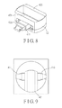
FIG. 8 is a fragmentary perspective view of the intermediate coupling of the first embodiment;
FIG. 9 is a view similar to FIG. 7, but illustrating a second coupling segment being moved relative to a first coupling segment;
FIG. 10 is an assembled perspective view of a modification of the second coupling segment;
FIG. 11 is an exploded perspective view of the modification of the second coupling segment;
FIG. 12 is an assembled perspective view of another modification of the second coupling segment;
FIG. 13 is an exploded perspective view of the another modification of the second coupling segment;
FIG. 14 is a sectional view of the another modification of the second coupling segment;
FIG. 15 is an exploded perspective view of the intermediate coupling of a second embodiment of a door mount mechanism according to the disclosure;
FIG. 16 is an assembled perspective view of the intermediate coupling of the second embodiment;
FIG. 17 is a sectional view of a variation of a first coupling segment and a third coupling segment of the intermediate coupling of the second embodiment;
FIG. 18 is an exploded perspective view of a modification of the intermediate coupling of the second embodiment;
FIG. 19 is an assembled perspective view of the modification of the intermediate coupling of the second embodiment;
FIG. 20 is a bottom view of the intermediate coupling of a third embodiment of a door mount mechanism according to the disclosure;
FIG. 21 a bottom view of the intermediate coupling of a fourth embodiment of a door mount mechanism according to the disclosure; and
FIG. 22 is a schematic, fragmentary exploded perspective view illustrating a variation of the second coupling segment.
DETAILED DESCRIPTION
Before the present invention is described in greater detail, it should be noted that like elements are denoted by the same reference numerals throughout the disclosure.
As shown in FIGS. 4 to 8, a first embodiment of a door mount mechanism according to the present disclosure is adapted for use in a smart lock system, and is adapted to be mounted onto a door (not shown) for rotating a thumb turn (not shown) of a door lock (not shown). The door lock includes a base plate (not shown) which is mounted on the door and on which the thumb turn is rotatably disposed. The door mount mechanism includes a casing 1, a rotatable component 2, an actuating unit 3 and an intermediate coupling 4.
The casing 1 includes a base wall 11, a surrounding wall 12 extending from a periphery of the base wall 11 and cooperating with the base wall 11 to define a receiving space 100 (see FIG. 7). In this embodiment, the base wall 11 is substantially square. The surrounding wall 12 has a door-mounting end 121, and the receiving space 100 has an opening 101 (see FIG. 7) at the door-mounting end 121. In this embodiment, the base wall 11 is formed with a round hole 111.
The rotatable component 2 is coupled rotatably to the casing 1. The rotatable component 2 has a base portion 21 engaging rotatably the round hole 111 of the casing 1, and a knob portion 22 projecting from the base portion 21 away from the receiving space 100 and being accessible to a user.
The actuating unit 3 includes an actuating module 31 that includes a motor and a solenoid valve, and a gear set 32 that is driven rotatably by the motor of the actuating module 31. The actuating unit 3 is connected to a control circuit (not shown). During operation of the smart lock system, the control circuit receives commands from a user device, such as a mobile phone, and the actuating unit 3 is activated by signals received from the control circuit to operate to drive rotation of the rotatable component 2.
The intermediate coupling 4 includes a first coupling segment 41 and a second coupling segment 42. In this embodiment, the second coupling segment 42 is made from an elastic material, is configured as a hollow frame, and has two parallel side frame sections 421 and two parallel elongated slide grooves 422 (only one is shown in FIG. 8) respectively formed in the side frame sections 421 and facing away from each other. The first coupling segment 41 has two subsegments 411. Each of the subsegments 411 is configured as a telescopic structure, and has a first end that is connected fixedly and co-rotatably to the rotatable component 2, and a second end that is opposite to the first end and that engages slidably a respective one of the slide grooves 422. Specifically, the subsegments 411 are collinearly arranged with each other and are perpendicular to the slide grooves 422. As such, a distance between the first and second ends of each of the subsegments 411 is adjustable, and the second coupling segment 42 is connected co-rotatably to and is linearly movable relative to the first coupling segment 41 (see FIGS. 8 and 9).
In use, the casing 1 is mounted onto the door with the door-mounting end 121 of the surrounding wall 12 abutting against the door and surrounding the base plate of the door lock, and with the door lock extending into the receiving space 100 through the opening 101 until the thumb turn of the door lock is surrounded by and inserted into the second coupling segment 42. During the interconnection between the second coupling segment 42 and the thumb turn of the door lock, due to the elasticity of the side frame sections 421 and the length-adjustable, telescopic structure of the subsegments 411 of the first coupling segment 41, the side frame sections 421 are deformable in a first direction in which the subsegments 411 extend. In addition, the second coupling segment 42 is slidable relative to the first coupling segment 41 in a second direction perpendicular to the first direction. Therefore, the intermediate coupling 4 has a relatively great flexibility in terms of fitting onto the thumb turn of different sizes, shapes, or at various relative locations of the base plate. Therefore, when the actuating unit 3 is remotely controlled to actuate rotation of the rotatable component 2, the thumb turn is rotated together with the rotatable component 2. Moreover, with the knob portion 22 being accessible to the user, the rotatable component 2 can also be manually rotated.
FIGS. 10 and 11 illustrate a modification of the first embodiment, in which the second coupling segment 42 further has an extension section 423 that is coupled telescopically to the side frame sections 421, and a plurality of resilient members 424 that are disposed between the side frame sections 421 and the extension section 423, and that are located at corners of the extension section 423 for biasing the extension section 423 in a direction away from the side frame sections 421. Therefore, the intermediate coupling 4 (see FIG. 7) is capable of firmly holding a relatively large thumb turn with a distal end of the extension section 423 abutting resiliently against a base plate on which the thumb turn is rotatably mounted.
FIGS. 12 to 14 illustrate another modification of the first embodiment, in which the extension section 423 is formed with a plurality of positioning slots 4231, and the side frame sections 421 are formed with a plurality of positioning protrusions 4211 (only one is visible in FIG. 13). The user can manually move the extension section 423 relative to the side frame sections 421, and engage the positioning protrusions 4211 with corresponding ones of the positioning slots 4231 to position the extension section 423 at a desired position relative to the side frame sections 421.
As shown in FIGS. 15 and 16, the second embodiment of a door mount mechanism according to the present disclosure differs from the first embodiment in the configuration of the intermediate coupling 4.
In this embodiment, the intermediate coupling 4 further includes a third coupling segment 43 interposed between the first and second coupling segments 41, 42. The intermediate coupling 4 is configured as an oldham coupling. Specifically, the first coupling segment 41 has a plate section 4101 that is formed with an elongated groove 4102, and an engaging section 4103 that projects at a side opposite to the elongated groove 4102 to be connected co-rotatably to the rotatable component 2 (see FIG. 4). The third coupling segment 43 has a surface that faces the first coupling segment 41 and an elongated tongue 4301 that is formed on the surface and that fittingly and slidably engages the elongated groove 4102. The second and third coupling segments 42, 43 are coupled together via a similar tongue-and-groove mechanism, but the elongated tongue and groove provided between the second third coupling segments 42, 43 are perpendicular to those provided between the first and third coupling segments 41, 43.
It should be noted that, the second coupling segment 42 may be modified into a set of substitutable coupling heads. As shown in FIGS. 18 and 19, each of the coupling heads has a main body 4201 which is formed with a cavity 4202 of a specific shape adapted to be fitted with a thumb turn having the same shape. For example, for a thumb turn shaped substantially rectangular, one of the coupling heads with the cavity 4202 being formed to be substantially rectangular is chosen to fit onto the thumb turn.
It should be further noted that, while the elongated groove 4102 is formed only in the plate section 4101 in this embodiment, the elongated groove 4102 may be formed through the plate section 4101 into the engaging section 4103 in other embodiments (see FIG. 17), so that the thickness of the plate section 4101 can be decreased, thereby miniaturizing the intermediate coupling 4.
As shown in FIG. 20, the third embodiment of a door mount mechanism according to the present disclosure differs from the previous embodiments in the configuration of the intermediate coupling 4.
In this embodiment, the third coupling segment 43 is larger than and surrounds the second coupling segment 42. The second coupling segment 42 has opposite edges coupled slidably and respectively to the third coupling segment 43 via tongue-and-groove mechanisms. The first coupling segment 41 is larger than and surrounds the third coupling segment 43, and the third coupling segment 43 has opposite edges coupled slidably and respectively to the first coupling segment 41 via tongue-and-groove mechanisms (which are not co-rotatable with the first coupling segment 41), such that the second coupling segment 42 is movable relative to the first coupling segment 41 in a first direction, and is movable relative to the first coupling segment 41 via the third coupling segment 43 in a second direction perpendicular to the first direction. In addition, the second coupling segment 42 has a rigid outer part 428 coupled slidably to the third coupling segment 43, and a rotatable inner part 427 surrounded by the rigid outer part 428, formed with a cavity 4271 that is adapted to receive the thumb turn of the door lock, and made from an elastic material so that the second coupling segment 42 can fit on thumb turns of different shapes and sizes.
Referring to FIG. 21, the fourth embodiment of a door mount mechanism according to the present disclosure differs from the previous embodiments in the configuration of the intermediate coupling 4.
In this embodiment, the first coupling segment 41 has two subsegments 411′ connected to a periphery of the rotatable component 2 (see FIG. 4). Each of the subsegments 411′ has opposite first and second ends. The first ends of the subsegments 411′ are aligned with each other in a first direction, and the second ends of the subsegments 411′ are aligned with each other in the first direction. The second coupling segment 42 has a main subsegment 421′ adapted for surrounding the thumb turn of the door lock, and four coupling subsegments 423. Two of the coupling subsegments 423 are connected to an end of the main subsegment 421′ and are connected slidably and respectively to the first and second ends of one of the subsegments 411′. The other two of the coupling segments 423 are connected to an opposite end of the main subsegment 421′ and are connected slidably and respectively to the first and second ends of the other one of the subsegments 411′. As such, the second coupling segment 42 is movable relative to the first coupling segment 41 in the first direction. Moreover, the main subsegment 421′ has a width in a second direction perpendicular to the first direction and adapted to be larger than that of the thumb turn. As such, when the thumb turn is eccentric relative to a center of the base plate of the door lock, the main subsegment 421′ would be allowed to be movable relative to the thumb turn in the second direction to thereby properly dri ye rotation of the thumb turn.
It should be noted that, referring to FIG. 22, the second coupling segment 42 may be configured to have a base board 420 and a driving bar 425 projecting co-rotatably from the base board 420 and eccentrically disposed on the base board 420. The second coupling segment 42 is adapted to push the thumb turn 90 of the door lock to rotate using the driving bar 425 and there is no need for any part of the second coupling segment 42 to be elastic and deformable.
It should be further noted that, the door mount mechanism according to the present disclosure may also be used for rotating a knob of a switch mechanism, such as a switch knob of a washing machine, an oven, and so on.
While the disclosure has been described in connection with what are considered the exemplary embodiments, it is understood that this disclosure is not limited to the disclosed embodiments but is intended to cover various arrangements included within the spirit and scope of the broadest interpretation so as to encompass all such modifications and equivalent arrangements.

Claims (15)

What is claimed is:
1. A door mount mechanism for a smart lock system, said door mount mechanism being adapted to be mounted onto a door for rotating a thumb turn of a door lock which is mounted on the door, said door mount mechanism comprising:
a casing having a door-mounting end that is adapted for abutting against the door, and defining a receiving space that is adapted for receiving the door lock, and that has an opening at said door-mounting end and adapted for extension of the door lock therethrough;
a rotatable component coupled rotatably to said casing; and
an intermediate coupling including
a first coupling segment that is connected co-rotatably to said rotatable component, and
a second coupling segment that is connected co-rotatably to said first coupling segment, that is linearly movable relative to said first coupling segment in a first direction perpendicular to an axis about which the thumb turn rotates and a second direction perpendicular to the axis and perpendicular to the first direction, and that is adapted for driving rotation of the thumb turn of the door lock such that the thumb turn is co-rotatable with said rotatable component.
2. The door mount mechanism as claimed in claim 1, wherein said second coupling segment of said intermediate coupling is made from an elastic material.
3. The door mount mechanism as claimed in claim 1, wherein:
said second coupling segment of said intermediate coupling is configured as a hollow frame that is adapted for surrounding the thumb turn of the door lock, and that has two parallel side frame sections and two parallel slide grooves respectively formed in said side frame sections; and
said first coupling segment of said intermediate coupling has two subsegments, each having a first end that is connected co-rotatably to said rotatable component, and a second end that is opposite to said first end and that engages slidably a respective one of said slide grooves.
4. The door mount mechanism as claimed in claim 3, wherein:
said side frame sections of said second coupling segment are made from an elastic material; and
each of said subsegments of said first coupling segment is configured as a telescopic structure, such that a distance between said first and second ends is adjustable.
5. The door mount mechanism as claimed in claim 3, wherein said second coupling segment further has an extension section that is coupled telescopically to said side frame sections, and a plurality of resilient members that are disposed between said side frame sections and said extension section for biasing said extension section away from said side frame sections.
6. The door mount mechanism as claimed in claim 3, wherein said second coupling segment further has an extension section that is coupled telescopically to said side frame sections, said extension section being formed with a plurality of positioning slots, said side frame sections being formed with a plurality of positioning protrusions for engaging corresponding ones of said positioning slots to position said extension section at a desired position relative to said side frame sections.
7. The door mount mechanism as claimed in claim 1, wherein said first and second coupling segments of said intermediate coupling are provided with a tongue-and-groove mechanism so that said second coupling segment is linearly movable relative to said first coupling segment.
8. The door mount mechanism as claimed in claim 7, wherein:
said intermediate coupling further includes a third coupling segment that is interposed between said first and second coupling segments;
said third coupling segment is linearly movable relative to said first coupling segment in the first direction; and
said second coupling segment is linearly movable relative to said first coupling segment in the second direction.
9. The door mount mechanism as claimed in claim 8, wherein:
said first coupling segment has a plate section formed with an elongated groove, and an engaging section projecting at a side opposite of said elongated groove and connected co-rotatably to said rotatable component; and
said third coupling segment has a surface facing said first coupling segment, and an elongated tongue formed on said surface and fittingly and slidably engaging said elongated groove.
10. The door mount mechanism as claimed in claim 9, wherein said elongated groove of said first coupling segment is formed through said plate section into said engaging section.
11. The door mount mechanism as claimed in claim 1, wherein said rotatable component has a base portion connected to said first coupling segment of said intermediate coupling, and a knob portion projecting from said base portion away from said first coupling segment of said intermediate coupling.
12. The door mount mechanism as claimed in claim 1, wherein said second coupling segment of said intermediate coupling has a base board connected co-rotatably to said rotatable component, and a driving bar projecting co-rotatably from said base board for pushing the thumb turn of the door lock to rotate.
13. The door mount mechanism as claimed in claim 1, wherein said second coupling segment includes a set of substitutable coupling heads, each of said coupling heads having a main body that is formed with a cavity of a specific shape and adapted to be fitted with the thumb turn having the same shape.
14. A door mount mechanism for a smart lock system, said door mount mechanism being adapted to be mounted onto a door for rotating a thumb turn of a door lock which is mounted on the door, said door mount mechanism comprising:
a casing having a door-mounting end that is adapted for abutting against the door, and defining a receiving space that is adapted for receiving the door lock, and that has an opening at said door-mounting end and adapted for extension of the door lock therethrough;
a rotatable component coupled rotatably to said casing; and
an intermediate coupling including
a first coupling segment that is connected co-rotatably to said rotatable component, and
a second coupling segment that is connected co-rotatably to said first coupling segment, that is linearly movable relative to said first coupling segment in directions perpendicular to an axis about which the thumb turn rotates, and that is adapted for driving rotation of the thumb turn of the door lock such that the thumb turn is co-rotatable with said rotatable component,
wherein said first coupling segment of said intermediate coupling has two subsegments connected to a periphery of said rotatable component, each of said subsegments having opposite first and second ends, said first ends of said subsegments being aligned with each other in a first direction, said second ends of said subsegments being aligned with each other in the first direction; and
said second coupling segment of said intermediate coupling has a main subsegment adapted for surrounding the thumb turn of the door lock, and four coupling subsegments, two of said coupling subsegments being connected to an end of said main subsegment and connected slidably and respectively to said first and second ends of one of said subsegments of said first coupling segment, the other two of said coupling subsegments being connected to an opposite end of said main subsegment and connected slidably and respectively to said first and second ends of the other one of said subsegments of said first coupling segment, said main subsegment having a width in a second direction perpendicular to the first direction and adapted to be larger than that of the thumb turn.
15. A smart lock system comprising:
a control circuit for receiving commands from a user device; and
a mount mechanism adapted to be mounted onto a subject for rotating a knob of a switch mechanism which is mounted on the subject, and including:
a casing that has a mounting end adapted for abutting against the subject, and that defines a receiving space adapted for receiving the switch mechanism, and having an opening at said mounting end that is adapted for extension of the switch mechanism therethrough,
a rotatable component that is coupled rotatably to said casing,
an intermediate coupling that includes
a first coupling segment connected co-rotatably to said rotatable component, and
a second coupling segment connected co-rotatably to said first coupling segment, being linearly movable relative to said first coupling segment in a first direction perpendicular to an axis about which the knob rotates and a second direction perpendicular to the axis and perpendicular to the first direction, and adapted for driving rotation of the knob of the switch mechanism such that the knob is co-rotatable with said rotatable component, and
an actuating unit that is connected to said control circuit, said actuating unit being activated by signals that are received from said control circuit, and being adapted for rotating the knob via said intermediate coupling.
US15/117,139 2014-10-08 2015-10-07 Door mount mechanism for a smart lock system Active 2035-10-15 US10472859B2 (en)

Priority Applications (1)

Application Number Priority Date Filing Date Title
US15/117,139 US10472859B2 (en) 2014-10-08 2015-10-07 Door mount mechanism for a smart lock system

Applications Claiming Priority (5)

Application Number Priority Date Filing Date Title
US201462061204P 2014-10-08 2014-10-08
US201462061212P 2014-10-08 2014-10-08
US201462061209P 2014-10-08 2014-10-08
US15/117,139 US10472859B2 (en) 2014-10-08 2015-10-07 Door mount mechanism for a smart lock system
PCT/US2015/054505 WO2016057677A1 (en) 2014-10-08 2015-10-07 Door mount mechanism for a smart lock system

Publications (2)

Publication Number Publication Date
US20170002585A1 US20170002585A1 (en) 2017-01-05
US10472859B2 true US10472859B2 (en) 2019-11-12

Family

ID=55653723

Family Applications (1)

Application Number Title Priority Date Filing Date
US15/117,139 Active 2035-10-15 US10472859B2 (en) 2014-10-08 2015-10-07 Door mount mechanism for a smart lock system

Country Status (5)

Country Link
US (1) US10472859B2 (en)
EP (1) EP3204577A4 (en)
JP (2) JP3212775U (en)
CN (1) CN107250471B (en)
WO (1) WO2016057677A1 (en)

Cited By (4)

* Cited by examiner, † Cited by third party
Publication number Priority date Publication date Assignee Title
US11339589B2 (en) 2018-04-13 2022-05-24 Dormakaba Usa Inc. Electro-mechanical lock core
US11466473B2 (en) 2018-04-13 2022-10-11 Dormakaba Usa Inc Electro-mechanical lock core
US11913254B2 (en) 2017-09-08 2024-02-27 dormakaba USA, Inc. Electro-mechanical lock core
US11933076B2 (en) 2016-10-19 2024-03-19 Dormakaba Usa Inc. Electro-mechanical lock core

Families Citing this family (4)

* Cited by examiner, † Cited by third party
Publication number Priority date Publication date Assignee Title
US10087656B1 (en) * 2017-05-17 2018-10-02 Dee Cee Marketing, Inc. Keyless locking system
CN109594852B (en) * 2017-09-30 2020-11-06 古哲明 Transmission mechanism and door lock control device with same
US10769872B2 (en) 2018-12-19 2020-09-08 T-Mobile Usa, Inc. Multi-factor authentication with geolocation and short-range communication with indoor-outdoor detection
US11201873B2 (en) 2018-12-19 2021-12-14 T-Mobile Usa, Inc. Multi-factor authentication with geolocation and voice command

Citations (17)

* Cited by examiner, † Cited by third party
Publication number Priority date Publication date Assignee Title
US4557124A (en) * 1983-05-10 1985-12-10 Norman Russ Power key turner
US5592839A (en) * 1993-03-24 1997-01-14 Hasan; Noam Assembly for retaining of keys of similar objects
US5678436A (en) * 1995-11-28 1997-10-21 Alexander; Curtis Earl Remote control door lock system
US5704235A (en) * 1994-12-24 1998-01-06 Staehle; Kurt Key case for an ignition key
US5887468A (en) * 1994-03-22 1999-03-30 Hasan; Noam Assembly for retaining of keys or similar objects
US6216502B1 (en) * 2000-04-04 2001-04-17 Thomas Cannella Keyless locking system
US6324879B1 (en) 1999-09-22 2001-12-04 Samuel Kennedy Deadbolt cover
US6591643B1 (en) 2001-12-10 2003-07-15 Thomas Cannella Keyless locking system
US6742369B1 (en) 2002-02-01 2004-06-01 Pierre Veillette Auxiliary door lock
US7373795B2 (en) 2004-12-07 2008-05-20 Kilbourne Mark W Universal remote deadbolt adapter
US20080296912A1 (en) 2007-05-29 2008-12-04 Whitner Douglas E Remote door access device
US20090084147A1 (en) 2007-09-28 2009-04-02 Aiphone Co., Ltd. Electric lock device
CA2789278C (en) 2009-04-10 2014-04-15 Emtek Products, Inc. Keypad lockset
US20140260447A1 (en) * 2013-03-15 2014-09-18 Merrick Schmidt-Lackner Door entry system
US9476232B1 (en) * 2015-12-29 2016-10-25 Roberto Verdecia Remote switch controller
US20170002586A1 (en) * 2015-07-01 2017-01-05 Dominick S. LEE Installation-Free Rechargeable Door Locking Apparatus, Systems and Methods
US9624695B1 (en) * 2013-03-15 2017-04-18 August Home, Inc. Intelligent door lock system with WiFi bridge

Family Cites Families (4)

* Cited by examiner, † Cited by third party
Publication number Priority date Publication date Assignee Title
KR20050041843A (en) * 2004-02-23 2005-05-04 김기영 A lock installation of a door
AU2009240836B2 (en) * 2008-12-02 2015-05-21 Assa Abloy Australia Pty Limited Adjustable Cylindrical Lock Set
JP5312965B2 (en) * 2009-01-28 2013-10-09 アイホン株式会社 Electric lock device
CN202117431U (en) * 2011-06-02 2012-01-18 姚海平 Fingerprint lock with integrated key lock

Patent Citations (18)

* Cited by examiner, † Cited by third party
Publication number Priority date Publication date Assignee Title
US4557124A (en) * 1983-05-10 1985-12-10 Norman Russ Power key turner
US5592839A (en) * 1993-03-24 1997-01-14 Hasan; Noam Assembly for retaining of keys of similar objects
US5887468A (en) * 1994-03-22 1999-03-30 Hasan; Noam Assembly for retaining of keys or similar objects
US5704235A (en) * 1994-12-24 1998-01-06 Staehle; Kurt Key case for an ignition key
US5678436A (en) * 1995-11-28 1997-10-21 Alexander; Curtis Earl Remote control door lock system
US6324879B1 (en) 1999-09-22 2001-12-04 Samuel Kennedy Deadbolt cover
US6216502B1 (en) * 2000-04-04 2001-04-17 Thomas Cannella Keyless locking system
US6591643B1 (en) 2001-12-10 2003-07-15 Thomas Cannella Keyless locking system
US6742369B1 (en) 2002-02-01 2004-06-01 Pierre Veillette Auxiliary door lock
US7373795B2 (en) 2004-12-07 2008-05-20 Kilbourne Mark W Universal remote deadbolt adapter
US20080296912A1 (en) 2007-05-29 2008-12-04 Whitner Douglas E Remote door access device
US20090084147A1 (en) 2007-09-28 2009-04-02 Aiphone Co., Ltd. Electric lock device
CA2789278C (en) 2009-04-10 2014-04-15 Emtek Products, Inc. Keypad lockset
US20140260447A1 (en) * 2013-03-15 2014-09-18 Merrick Schmidt-Lackner Door entry system
US8869574B2 (en) * 2013-03-15 2014-10-28 Consumer 2.0, Inc. Door entry system
US9624695B1 (en) * 2013-03-15 2017-04-18 August Home, Inc. Intelligent door lock system with WiFi bridge
US20170002586A1 (en) * 2015-07-01 2017-01-05 Dominick S. LEE Installation-Free Rechargeable Door Locking Apparatus, Systems and Methods
US9476232B1 (en) * 2015-12-29 2016-10-25 Roberto Verdecia Remote switch controller

Non-Patent Citations (1)

* Cited by examiner, † Cited by third party
Title
International Search Report, PCT/US15/054505, dated Jan. 5, 2016 (2 pages).

Cited By (5)

* Cited by examiner, † Cited by third party
Publication number Priority date Publication date Assignee Title
US11933076B2 (en) 2016-10-19 2024-03-19 Dormakaba Usa Inc. Electro-mechanical lock core
US11913254B2 (en) 2017-09-08 2024-02-27 dormakaba USA, Inc. Electro-mechanical lock core
US11339589B2 (en) 2018-04-13 2022-05-24 Dormakaba Usa Inc. Electro-mechanical lock core
US11447980B2 (en) 2018-04-13 2022-09-20 Dormakaba Usa Inc. Puller tool
US11466473B2 (en) 2018-04-13 2022-10-11 Dormakaba Usa Inc Electro-mechanical lock core

Also Published As

Publication number Publication date
JP3212775U (en) 2017-10-05
WO2016057677A1 (en) 2016-04-14
JP2018028261A (en) 2018-02-22
CN107250471B (en) 2020-03-17
EP3204577A4 (en) 2018-06-20
CN107250471A (en) 2017-10-13
EP3204577A1 (en) 2017-08-16
US20170002585A1 (en) 2017-01-05
JP6641342B2 (en) 2020-02-05

Similar Documents

Publication Publication Date Title
US10472859B2 (en) Door mount mechanism for a smart lock system
US20160040452A1 (en) Door mount mechanism for a smart lock system
US7770423B2 (en) Electro-mechanical lock structure
US8851351B2 (en) Trigger assembly for switching one shoot mode or repeat shoot mode
CN109995973B (en) Functional module, electronic device and control method of electronic device
US9790677B2 (en) Remote control device
CN106032005B (en) Screw release device with guide function
US11187008B2 (en) Clutch engagement assembly of door lock and driving device thereof
US20150211260A1 (en) Gear Structure for Electronic Lock
MY147680A (en) Electromechanical lock device
US9395755B2 (en) Dock for controlling and adjusting viewing angle of electronic devices
CN105700633B (en) There is the Quick Release rotating mechanism of positioning function and has the electronic device of position rotating door-plate
EP2682549B1 (en) Case latch assembly
US8873229B2 (en) Electronic device having card holder
JP6897995B2 (en) Switch device
EP3223295A1 (en) Switch device
KR102584586B1 (en) Vehicle key device
CN109736647B (en) Locking mechanism and lock
JP6228156B2 (en) Two-rotation shaft device for flip electronic products
TWI668356B (en) Electronic lock Label mechanism
US9976637B2 (en) Rotary electric component
TWI611967B (en) A lock for a vehicle
US9362069B1 (en) Multi-command trigger switch
KR102248002B1 (en) Glass door lock apparatus
KR102248001B1 (en) Glass door lock apparatus

Legal Events

Date Code Title Description
AS Assignment

Owner name: CANDY HOUSE INC., CALIFORNIA

Free format text: ASSIGNMENT OF ASSIGNORS INTEREST;ASSIGNOR:KU, CHE-MING;REEL/FRAME:039738/0673

Effective date: 20160831

STPP Information on status: patent application and granting procedure in general

Free format text: FINAL REJECTION MAILED

STPP Information on status: patent application and granting procedure in general

Free format text: DOCKETED NEW CASE - READY FOR EXAMINATION

STPP Information on status: patent application and granting procedure in general

Free format text: NOTICE OF ALLOWANCE MAILED -- APPLICATION RECEIVED IN OFFICE OF PUBLICATIONS

STPP Information on status: patent application and granting procedure in general

Free format text: PUBLICATIONS -- ISSUE FEE PAYMENT VERIFIED

STCF Information on status: patent grant

Free format text: PATENTED CASE

FEPP Fee payment procedure

Free format text: SURCHARGE FOR LATE PAYMENT, SMALL ENTITY (ORIGINAL EVENT CODE: M2554); ENTITY STATUS OF PATENT OWNER: SMALL ENTITY

MAFP Maintenance fee payment

Free format text: PAYMENT OF MAINTENANCE FEE, 4TH YR, SMALL ENTITY (ORIGINAL EVENT CODE: M2551); ENTITY STATUS OF PATENT OWNER: SMALL ENTITY

Year of fee payment: 4