US10464763B2 - Apparatus for handing and moving a stack of tires - Google Patents
Apparatus for handing and moving a stack of tires Download PDFInfo
- Publication number
- US10464763B2 US10464763B2 US15/333,225 US201615333225A US10464763B2 US 10464763 B2 US10464763 B2 US 10464763B2 US 201615333225 A US201615333225 A US 201615333225A US 10464763 B2 US10464763 B2 US 10464763B2
- Authority
- US
- United States
- Prior art keywords
- tire
- tires
- tire support
- machine
- alignment position
- Prior art date
- Legal status (The legal status is an assumption and is not a legal conclusion. Google has not performed a legal analysis and makes no representation as to the accuracy of the status listed.)
- Active - Reinstated
Links
- 238000009434 installation Methods 0.000 abstract description 7
- 230000007246 mechanism Effects 0.000 description 1
- 230000004048 modification Effects 0.000 description 1
- 238000012986 modification Methods 0.000 description 1
- 238000005096 rolling process Methods 0.000 description 1
Images


Classifications
-
- B—PERFORMING OPERATIONS; TRANSPORTING
- B65—CONVEYING; PACKING; STORING; HANDLING THIN OR FILAMENTARY MATERIAL
- B65G—TRANSPORT OR STORAGE DEVICES, e.g. CONVEYORS FOR LOADING OR TIPPING, SHOP CONVEYOR SYSTEMS OR PNEUMATIC TUBE CONVEYORS
- B65G59/00—De-stacking of articles
- B65G59/08—De-stacking after preliminary tilting of the stack
-
- B—PERFORMING OPERATIONS; TRANSPORTING
- B65—CONVEYING; PACKING; STORING; HANDLING THIN OR FILAMENTARY MATERIAL
- B65G—TRANSPORT OR STORAGE DEVICES, e.g. CONVEYORS FOR LOADING OR TIPPING, SHOP CONVEYOR SYSTEMS OR PNEUMATIC TUBE CONVEYORS
- B65G2201/00—Indexing codes relating to handling devices, e.g. conveyors, characterised by the type of product or load being conveyed or handled
- B65G2201/02—Articles
- B65G2201/0273—Tires
-
- B—PERFORMING OPERATIONS; TRANSPORTING
- B65—CONVEYING; PACKING; STORING; HANDLING THIN OR FILAMENTARY MATERIAL
- B65G—TRANSPORT OR STORAGE DEVICES, e.g. CONVEYORS FOR LOADING OR TIPPING, SHOP CONVEYOR SYSTEMS OR PNEUMATIC TUBE CONVEYORS
- B65G57/00—Stacking of articles
- B65G57/28—Stacking of articles by assembling the articles and tilting the assembled articles to a stacked position
Definitions
- This invention relates to a machine and apparatus for handling and moving a stack of mounted tires at a receiving facility.
- tires that are mounted on wheel-rims When tires that are mounted on wheel-rims are shipped from the tire supplier to the equipment builder or similar facility for use, they typically are stacked vertically, lying flat on top of each other. This is generally referred to as “barrel stacking.”
- the barrel stacks may be shipped on a pallet or without a pallet. This is the most efficient use of space, and minimizes the cost of shipping as well as the space required at the equipment builder or receiving facility to store the tires.
- the barrel stack presents problems in reaching and removing units of one or more tires from the top of the stack for use, and lifting the units from a flat position to an upright position for moving and installation.
- the present invention addresses these problems.
- the present invention comprises a rotary apparatus or machine that takes or receives a barrel stack of mounted tires in the vertical position (i.e., barrel stacked), and rotates the stack as a whole to a horizontal position, where each unit or tire is an upright position.
- the tires can then be rolled off individually or in multiple units to be installed on the equipment being built, or transported from the tire holding area to the assembly floor or installation area.
- FIGS. 1-2 show the rotary apparatus in a loading position.
- FIGS. 3-4 show the rotary apparatus midway between a loading position and an off-loading position.
- FIGS. 5-6 show the rotary apparatus in an off-loading position.
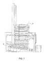
- FIG. 7 shows barrel stacked tires on a pallet loaded on the rotary apparatus.
- FIG. 8 shows the rotary apparatus with tires midway between a loading position and an off-loading position.
- FIGS. 9-10 show the rotary apparatus with tires in an off-loading position.
- FIG. 11 shows a tire cage or rack for use with the rotary apparatus.
- the present invention comprises a rotary apparatus or machine 2 that takes or receives a barrel stack of mounted tires 4 in the vertical position (i.e., barrel stacked), and rotates the stack as a whole to a horizontal position, where each unit or tire is an upright position.
- the tires can then be rolled off individually or in multiple units to be installed on the equipment being built, or transported from the tire holding area to the assembly floor or installation area.
- FIGS. 1 and 2 show the apparatus in a loading position ready to receive a barrel stack of tires.
- the apparatus comprises a receiving area 20 for receiving a barrel stack of tires, which may or may not be placed on a pallet.
- the receiving area comprises a railing along two sides, with a security gate 22 along a third side.
- the security gate when open, allows access to the receiving floor 30 , which may or may not contain rollers 32 to help the barrel stack of tires 4 roll up the receiving ramp 24 and onto the receiving floor 30 .
- a tire support beam 40 is attached to one side of the receiving floor 30 .
- the tire support beam and receiving floor pivot together, as seen in FIGS. 1-5 , so that the support beam 40 moves from a vertical position (i.e., a loading position) to a horizontal, or approximately horizontal position, while the receiving floor 30 simultaneously moves from a flat position to a raised, tilted or vertical position. In the latter position (i.e., the off-loading position), the tire support beam 40 is generally flush with the top end of the off-loading ramp 50 .
- the tire support beam in the off-loading position is not fully horizontal (i.e., at a slight angle upward, with the top of the support beam being somewhat higher in elevation than the bottom of the support beam where attached to the receiving floor). This angle assists in keeping tires in place when off-loading.
- Movement of the tire support beam and receiving floor is achieved by one or more piston mechanisms 44 .
- the piston may be controlled by a control device on the apparatus, or remotely, or both.
- the tire support beam 40 may be unitary, or, as seen in FIGS. 1-5 , comprise two component beam with a gap 42 in the middle.
- the gap helps hold the tires in place when the device is moved to the off-loading position.
- the inside edges of one or both components beams are beveled to help secure the tires in place, while assisting in rolling the tires off the tire support beam when off-loading.
- the pivot point is along the side of the receiving floor where the support beam is attached, and the receiving cage railings and security gate remain in place.
- the security gate 22 opens only when the receiving floor is in a flat position (as seen in FIG. 1 ), and is closed and cannot be opened when the receiving floor and tire support beam are being moved, or the receiving floor is in a raised position, as seen in FIG. 6 .
- one or more security arms 52 may be placed across the front of the apparatus at or near the top of the off-loading ramp 50 . These security arms may be lowered to prevent access to the offloading area when the device is in operation, or in some instances, when the device is in the loading position.
- FIGS. 7-9 show the same apparatus with tires in place.
- FIG. 7 shows a barrel stack of tires with a security tie 60 on a pallet 62 already loaded on the apparatus, which is in a loading position. A stack of tires can be moved without a security tie.
- FIGS. 8-10 show the tires being moved to the off-loading position.
- tires When in the off-loading position, tires can then be rolled off the stack and down the off-loading ramp 50 individually or in groups as needed.
- the device itself may be mobile, and moved close to the assembly floor or installation area (i.e., where the tires are installed).
- the device also may be relative immobile and fixed in place. In the latter case, the barrel tires moved to the assembly floor or installation area by other means.
- a barrel stack may be transported to and placed in the rotary machine by a variety of means known in the art, including a forklift.
- the barrel stack may be secured by a tie, as seen in FIG. 7 , or may be unsecured.
- a mobile or movable tire cage or rack 70 may be used in conjunction with the rotary apparatus described above.
- the cage may be wheeled or not wheeled.
- the cage is placed on or rolled onto the rotary machine, typically in a horizontal position (i.e., the off-loading position for tires), and then rotated to a vertical position (i.e., the loading position for tires).
- the barrel stack of tires is then placed or loaded in the cage on the machine, and the machine rotates the cage back to a horizontal position.
- the cage can then be removed from the machine and moved (such as by a forklift or similar means) or rolled from the tire holding area to the assembly floor or installation area, and tires rolled off individually or in multiple units from the cage, to be installed on the equipment being built as needed.
- a plurality of cages may thus be used with the rotary machine to handle multiple barrel stacks.
Abstract
Description
Claims (12)
Priority Applications (2)
| Application Number | Priority Date | Filing Date | Title |
|---|---|---|---|
| US15/333,225 US10464763B2 (en) | 2013-03-29 | 2016-10-25 | Apparatus for handing and moving a stack of tires |
| US16/674,024 US20200140213A1 (en) | 2013-03-29 | 2019-11-05 | Apparatus for handing and moving a stack of tires |
Applications Claiming Priority (3)
| Application Number | Priority Date | Filing Date | Title |
|---|---|---|---|
| US201361806714P | 2013-03-29 | 2013-03-29 | |
| US14/230,699 US9475659B2 (en) | 2013-03-29 | 2014-03-31 | Apparatus for handing and moving a stack of tires |
| US15/333,225 US10464763B2 (en) | 2013-03-29 | 2016-10-25 | Apparatus for handing and moving a stack of tires |
Related Parent Applications (1)
| Application Number | Title | Priority Date | Filing Date |
|---|---|---|---|
| US14/230,699 Continuation US9475659B2 (en) | 2013-03-29 | 2014-03-31 | Apparatus for handing and moving a stack of tires |
Related Child Applications (1)
| Application Number | Title | Priority Date | Filing Date |
|---|---|---|---|
| US16/674,024 Continuation US20200140213A1 (en) | 2013-03-29 | 2019-11-05 | Apparatus for handing and moving a stack of tires |
Publications (2)
| Publication Number | Publication Date |
|---|---|
| US20170036870A1 US20170036870A1 (en) | 2017-02-09 |
| US10464763B2 true US10464763B2 (en) | 2019-11-05 |
Family
ID=51621022
Family Applications (3)
| Application Number | Title | Priority Date | Filing Date |
|---|---|---|---|
| US14/230,699 Active - Reinstated US9475659B2 (en) | 2013-03-29 | 2014-03-31 | Apparatus for handing and moving a stack of tires |
| US15/333,225 Active - Reinstated US10464763B2 (en) | 2013-03-29 | 2016-10-25 | Apparatus for handing and moving a stack of tires |
| US16/674,024 Abandoned US20200140213A1 (en) | 2013-03-29 | 2019-11-05 | Apparatus for handing and moving a stack of tires |
Family Applications Before (1)
| Application Number | Title | Priority Date | Filing Date |
|---|---|---|---|
| US14/230,699 Active - Reinstated US9475659B2 (en) | 2013-03-29 | 2014-03-31 | Apparatus for handing and moving a stack of tires |
Family Applications After (1)
| Application Number | Title | Priority Date | Filing Date |
|---|---|---|---|
| US16/674,024 Abandoned US20200140213A1 (en) | 2013-03-29 | 2019-11-05 | Apparatus for handing and moving a stack of tires |
Country Status (1)
| Country | Link |
|---|---|
| US (3) | US9475659B2 (en) |
Cited By (1)
| Publication number | Priority date | Publication date | Assignee | Title |
|---|---|---|---|---|
| US20200140213A1 (en) * | 2013-03-29 | 2020-05-07 | David Strickland, III | Apparatus for handing and moving a stack of tires |
Families Citing this family (6)
| Publication number | Priority date | Publication date | Assignee | Title |
|---|---|---|---|---|
| FR3040987A1 (en) * | 2015-09-15 | 2017-03-17 | Michelin & Cie | DEVICE FOR HANDLING PNEUMATIC ENVELOPES |
| EP3476778B1 (en) * | 2017-10-27 | 2020-09-02 | Gawronski GmbH | Method and device for handling tyres |
| CN108312382A (en) * | 2018-03-06 | 2018-07-24 | 江苏中宏环保科技有限公司 | Tire feeding device |
| KR102538888B1 (en) * | 2018-11-19 | 2023-06-01 | 무라다기카이가부시끼가이샤 | posture change device |
| US10933692B1 (en) | 2019-11-19 | 2021-03-02 | Delta Air Lines, Inc. | Wheel righting apparatus |
| SE1900202A1 (en) * | 2019-11-25 | 2021-05-26 | Fettavskiljaren Sverige Ab | Stack handler |
Citations (23)
| Publication number | Priority date | Publication date | Assignee | Title |
|---|---|---|---|---|
| US1871395A (en) * | 1930-06-25 | 1932-08-09 | Co Bartlett & Snow Co | Upsetting device for barrels and like articles |
| US2101738A (en) * | 1936-10-01 | 1937-12-07 | Logan Co Inc | Coil handling apparatus |
| US2667279A (en) * | 1951-01-08 | 1954-01-26 | Francis B Fishburne | Hogshead handling apparatus |
| US2974812A (en) * | 1958-08-21 | 1961-03-14 | Bopp Mfg Inc | Load-handling apparatus for building blocks and the like |
| US3021018A (en) * | 1958-01-06 | 1962-02-13 | Homer D Paxson | Coil turning device |
| US3521763A (en) * | 1969-01-02 | 1970-07-28 | Velten & Pulver | Automatic pan unstacker |
| US3583575A (en) * | 1967-10-17 | 1971-06-08 | Lawrence Jowsey | Roll delivery apparatus |
| US3850295A (en) * | 1971-10-12 | 1974-11-26 | B Black | Tire shipping and storage structure |
| US3883007A (en) * | 1971-07-19 | 1975-05-13 | Upenders Inc | Materials handling apparatus |
| US4032023A (en) * | 1976-03-29 | 1977-06-28 | Gas-Fired Products, Inc. | Apparatus for loading tobacco in barns |
| US4042234A (en) * | 1976-06-18 | 1977-08-16 | Rengo Kabushiki Kaisha, (Rengo Co. Ltd.) | Blank feeding machine |
| US4103786A (en) * | 1975-10-11 | 1978-08-01 | Rengo Co., Ltd. | Board piling-up apparatus |
| US4242029A (en) * | 1977-01-31 | 1980-12-30 | Musgrave Harry J | Poultry coop handling system |
| US4249847A (en) * | 1977-10-24 | 1981-02-10 | Rengo Co., Ltd. | Apparatus for transporting boards |
| US4293264A (en) * | 1979-12-07 | 1981-10-06 | Libbey-Owens-Ford Company | Pivotal shipping rack supporting apparatus |
| US5681141A (en) * | 1996-04-12 | 1997-10-28 | Critel; Dexter L. | Tire stacker |
| US5845356A (en) * | 1996-07-19 | 1998-12-08 | Braj Enterprise Inc. | Loading ramp and handling apparatus |
| US6050771A (en) * | 1997-09-22 | 2000-04-18 | Industrial Resources Of Michigan | Pallet workstation accumulator |
| US6298999B1 (en) * | 2000-09-01 | 2001-10-09 | Ricky B. Bellman | Tire storage rack |
| US6527499B2 (en) * | 2000-02-04 | 2003-03-04 | American Express Travel Related Services Company, Inc. | Automated tire loading/unloading and compression system and tire transport frame |
| US7150598B2 (en) * | 2002-05-10 | 2006-12-19 | Smets John S | Pallet handling apparatus and method |
| US8562280B1 (en) * | 2011-07-01 | 2013-10-22 | Ecmd, Inc. | Warehouse storage system |
| US9475659B2 (en) * | 2013-03-29 | 2016-10-25 | David Strickland, III | Apparatus for handing and moving a stack of tires |
Family Cites Families (10)
| Publication number | Priority date | Publication date | Assignee | Title |
|---|---|---|---|---|
| US2776831A (en) * | 1953-01-09 | 1957-01-08 | S & S Corrugated Paper Mach | Sheet inverting mechanism |
| FR1582533A (en) * | 1968-06-25 | 1969-10-03 | ||
| US4022332A (en) * | 1975-07-16 | 1977-05-10 | General Corrugated Machinery Co., Inc. | Apparatus for orienting case blanks |
| SE412891B (en) * | 1979-06-20 | 1980-03-24 | Frigoscandia Ab | DEVICE FOR HANDLING OF LOW STACKED PALLASTATE GOODS |
| US4708583A (en) * | 1983-03-23 | 1987-11-24 | Moen Lenard E | Process of recubing boxes |
| US5788461A (en) * | 1996-02-02 | 1998-08-04 | Alvey, Inc. | Automatic depalletizer |
| US6357599B1 (en) * | 1999-09-01 | 2002-03-19 | Greif Bros. Corp. Of Ohio, Inc. | Machine and method for facilitating separation of members of a stack |
| WO2005118441A1 (en) * | 2004-05-27 | 2005-12-15 | Frazier Industrial Company | Pallet stacking and staging system |
| EP2008955A1 (en) * | 2007-06-30 | 2008-12-31 | Erhard Schmale | Assembly for collecting empty pallets, e.g. euro pallets |
| CA2813342C (en) * | 2010-09-29 | 2019-04-30 | Dealer Tire, Llc | Portable on-tread tire rack |
-
2014
- 2014-03-31 US US14/230,699 patent/US9475659B2/en active Active - Reinstated
-
2016
- 2016-10-25 US US15/333,225 patent/US10464763B2/en active Active - Reinstated
-
2019
- 2019-11-05 US US16/674,024 patent/US20200140213A1/en not_active Abandoned
Patent Citations (23)
| Publication number | Priority date | Publication date | Assignee | Title |
|---|---|---|---|---|
| US1871395A (en) * | 1930-06-25 | 1932-08-09 | Co Bartlett & Snow Co | Upsetting device for barrels and like articles |
| US2101738A (en) * | 1936-10-01 | 1937-12-07 | Logan Co Inc | Coil handling apparatus |
| US2667279A (en) * | 1951-01-08 | 1954-01-26 | Francis B Fishburne | Hogshead handling apparatus |
| US3021018A (en) * | 1958-01-06 | 1962-02-13 | Homer D Paxson | Coil turning device |
| US2974812A (en) * | 1958-08-21 | 1961-03-14 | Bopp Mfg Inc | Load-handling apparatus for building blocks and the like |
| US3583575A (en) * | 1967-10-17 | 1971-06-08 | Lawrence Jowsey | Roll delivery apparatus |
| US3521763A (en) * | 1969-01-02 | 1970-07-28 | Velten & Pulver | Automatic pan unstacker |
| US3883007A (en) * | 1971-07-19 | 1975-05-13 | Upenders Inc | Materials handling apparatus |
| US3850295A (en) * | 1971-10-12 | 1974-11-26 | B Black | Tire shipping and storage structure |
| US4103786A (en) * | 1975-10-11 | 1978-08-01 | Rengo Co., Ltd. | Board piling-up apparatus |
| US4032023A (en) * | 1976-03-29 | 1977-06-28 | Gas-Fired Products, Inc. | Apparatus for loading tobacco in barns |
| US4042234A (en) * | 1976-06-18 | 1977-08-16 | Rengo Kabushiki Kaisha, (Rengo Co. Ltd.) | Blank feeding machine |
| US4242029A (en) * | 1977-01-31 | 1980-12-30 | Musgrave Harry J | Poultry coop handling system |
| US4249847A (en) * | 1977-10-24 | 1981-02-10 | Rengo Co., Ltd. | Apparatus for transporting boards |
| US4293264A (en) * | 1979-12-07 | 1981-10-06 | Libbey-Owens-Ford Company | Pivotal shipping rack supporting apparatus |
| US5681141A (en) * | 1996-04-12 | 1997-10-28 | Critel; Dexter L. | Tire stacker |
| US5845356A (en) * | 1996-07-19 | 1998-12-08 | Braj Enterprise Inc. | Loading ramp and handling apparatus |
| US6050771A (en) * | 1997-09-22 | 2000-04-18 | Industrial Resources Of Michigan | Pallet workstation accumulator |
| US6527499B2 (en) * | 2000-02-04 | 2003-03-04 | American Express Travel Related Services Company, Inc. | Automated tire loading/unloading and compression system and tire transport frame |
| US6298999B1 (en) * | 2000-09-01 | 2001-10-09 | Ricky B. Bellman | Tire storage rack |
| US7150598B2 (en) * | 2002-05-10 | 2006-12-19 | Smets John S | Pallet handling apparatus and method |
| US8562280B1 (en) * | 2011-07-01 | 2013-10-22 | Ecmd, Inc. | Warehouse storage system |
| US9475659B2 (en) * | 2013-03-29 | 2016-10-25 | David Strickland, III | Apparatus for handing and moving a stack of tires |
Cited By (1)
| Publication number | Priority date | Publication date | Assignee | Title |
|---|---|---|---|---|
| US20200140213A1 (en) * | 2013-03-29 | 2020-05-07 | David Strickland, III | Apparatus for handing and moving a stack of tires |
Also Published As
| Publication number | Publication date |
|---|---|
| US20170036870A1 (en) | 2017-02-09 |
| US20140294552A1 (en) | 2014-10-02 |
| US9475659B2 (en) | 2016-10-25 |
| US20200140213A1 (en) | 2020-05-07 |
Similar Documents
| Publication | Publication Date | Title |
|---|---|---|
| US10464763B2 (en) | Apparatus for handing and moving a stack of tires | |
| US8113762B2 (en) | Horizontal pipe storage and handling system | |
| US10919697B2 (en) | Plate storage assembly | |
| JP6871291B2 (en) | Cargo loading and unloading device | |
| US20160280246A1 (en) | Hand Dolly with Electric Scissor Lift | |
| US20200039767A1 (en) | Automatic loading apparatus and application of the same | |
| CN104385251A (en) | Working position apparatus | |
| JP5197180B2 (en) | Stacking equipment | |
| JP6535835B2 (en) | Loading method and unloading method | |
| SE441172B (en) | DEVICE FOR TRANSPORT AND HANDLING OF CYLINDRICAL DEVICES | |
| US8950988B2 (en) | Method and apparatus for stacking loads in vehicles | |
| CN108367870A (en) | Equipment for mobile pallet | |
| JP2007070103A (en) | Automated warehouse for storing roll body and method for storing roll body | |
| US9517845B2 (en) | Movable personnel platform for unloading a unit load device | |
| JP2006341968A (en) | Article storage facility | |
| US10280047B2 (en) | Lifting jig for lifting elements along the facade of a building | |
| JP2009274863A (en) | Lifting device and cargo transshipping method using this lifting device | |
| US20160194164A1 (en) | Equipment and method for moving containers | |
| RU2666058C2 (en) | Lifting system for heavy loads | |
| FI130588B (en) | Load handling device and loader | |
| US9908723B2 (en) | Modular transportation systems, devices and methods | |
| KR100935868B1 (en) | Automatic warehouse | |
| RU2615896C1 (en) | Method for handling large cargo | |
| JP2014109101A (en) | Mechanical parking device | |
| CN219989782U (en) | Fork truck, general tray of ground ox |
Legal Events
| Date | Code | Title | Description |
|---|---|---|---|
| STPP | Information on status: patent application and granting procedure in general |
Free format text: NON FINAL ACTION MAILED |
|
| STPP | Information on status: patent application and granting procedure in general |
Free format text: NOTICE OF ALLOWANCE MAILED -- APPLICATION RECEIVED IN OFFICE OF PUBLICATIONS |
|
| STCB | Information on status: application discontinuation |
Free format text: ABANDONED -- FAILURE TO PAY ISSUE FEE |
|
| STPP | Information on status: patent application and granting procedure in general |
Free format text: PUBLICATIONS -- ISSUE FEE PAYMENT RECEIVED |
|
| STCF | Information on status: patent grant |
Free format text: PATENTED CASE |
|
| FEPP | Fee payment procedure |
Free format text: MAINTENANCE FEE REMINDER MAILED (ORIGINAL EVENT CODE: REM.); ENTITY STATUS OF PATENT OWNER: SMALL ENTITY |
|
| LAPS | Lapse for failure to pay maintenance fees |
Free format text: PATENT EXPIRED FOR FAILURE TO PAY MAINTENANCE FEES (ORIGINAL EVENT CODE: EXP.); ENTITY STATUS OF PATENT OWNER: SMALL ENTITY |
|
| STCH | Information on status: patent discontinuation |
Free format text: PATENT EXPIRED DUE TO NONPAYMENT OF MAINTENANCE FEES UNDER 37 CFR 1.362 |
|
| PRDP | Patent reinstated due to the acceptance of a late maintenance fee |
Effective date: 20240103 |
|
| FP | Lapsed due to failure to pay maintenance fee |
Effective date: 20231105 |
|
| FEPP | Fee payment procedure |
Free format text: PETITION RELATED TO MAINTENANCE FEES FILED (ORIGINAL EVENT CODE: PMFP); ENTITY STATUS OF PATENT OWNER: SMALL ENTITY Free format text: PETITION RELATED TO MAINTENANCE FEES GRANTED (ORIGINAL EVENT CODE: PMFG); ENTITY STATUS OF PATENT OWNER: SMALL ENTITY Free format text: SURCHARGE, PETITION TO ACCEPT PYMT AFTER EXP, UNINTENTIONAL. (ORIGINAL EVENT CODE: M2558); ENTITY STATUS OF PATENT OWNER: SMALL ENTITY |
|
| MAFP | Maintenance fee payment |
Free format text: PAYMENT OF MAINTENANCE FEE, 4TH YR, SMALL ENTITY (ORIGINAL EVENT CODE: M2551); ENTITY STATUS OF PATENT OWNER: SMALL ENTITY Year of fee payment: 4 |
|
| STCF | Information on status: patent grant |
Free format text: PATENTED CASE |