US10443518B2 - Optimal firing patterns for cylinder deactivation control with limited deactivation mechanisms - Google Patents
Optimal firing patterns for cylinder deactivation control with limited deactivation mechanisms Download PDFInfo
- Publication number
- US10443518B2 US10443518B2 US15/655,416 US201715655416A US10443518B2 US 10443518 B2 US10443518 B2 US 10443518B2 US 201715655416 A US201715655416 A US 201715655416A US 10443518 B2 US10443518 B2 US 10443518B2
- Authority
- US
- United States
- Prior art keywords
- cylinders
- firing
- engine
- engine system
- controller
- Prior art date
- Legal status (The legal status is an assumption and is not a legal conclusion. Google has not performed a legal analysis and makes no representation as to the accuracy of the status listed.)
- Active, expires
Links
- 238000010304 firing Methods 0.000 title claims abstract description 104
- 230000009849 deactivation Effects 0.000 title claims abstract description 46
- 230000007246 mechanism Effects 0.000 title claims abstract description 35
- 239000000446 fuel Substances 0.000 claims description 13
- 239000000203 mixture Substances 0.000 claims description 6
- 238000000034 method Methods 0.000 description 15
- 230000006870 function Effects 0.000 description 5
- 230000003247 decreasing effect Effects 0.000 description 4
- 238000005086 pumping Methods 0.000 description 4
- 230000008901 benefit Effects 0.000 description 3
- 230000005540 biological transmission Effects 0.000 description 2
- 238000002485 combustion reaction Methods 0.000 description 2
- 238000010586 diagram Methods 0.000 description 2
- 230000000694 effects Effects 0.000 description 2
- 230000006872 improvement Effects 0.000 description 2
- 230000004913 activation Effects 0.000 description 1
- 230000001276 controlling effect Effects 0.000 description 1
- 230000007423 decrease Effects 0.000 description 1
- 230000006698 induction Effects 0.000 description 1
- 238000002372 labelling Methods 0.000 description 1
- 230000000116 mitigating effect Effects 0.000 description 1
- 230000010363 phase shift Effects 0.000 description 1
- 230000009467 reduction Effects 0.000 description 1
- 230000001105 regulatory effect Effects 0.000 description 1
- 230000007704 transition Effects 0.000 description 1
- 238000011144 upstream manufacturing Methods 0.000 description 1
Images


Classifications
-
- F—MECHANICAL ENGINEERING; LIGHTING; HEATING; WEAPONS; BLASTING
- F02—COMBUSTION ENGINES; HOT-GAS OR COMBUSTION-PRODUCT ENGINE PLANTS
- F02D—CONTROLLING COMBUSTION ENGINES
- F02D41/00—Electrical control of supply of combustible mixture or its constituents
- F02D41/008—Controlling each cylinder individually
- F02D41/0087—Selective cylinder activation, i.e. partial cylinder operation
-
- F—MECHANICAL ENGINEERING; LIGHTING; HEATING; WEAPONS; BLASTING
- F02—COMBUSTION ENGINES; HOT-GAS OR COMBUSTION-PRODUCT ENGINE PLANTS
- F02D—CONTROLLING COMBUSTION ENGINES
- F02D17/00—Controlling engines by cutting out individual cylinders; Rendering engines inoperative or idling
- F02D17/02—Cutting-out
-
- F—MECHANICAL ENGINEERING; LIGHTING; HEATING; WEAPONS; BLASTING
- F02—COMBUSTION ENGINES; HOT-GAS OR COMBUSTION-PRODUCT ENGINE PLANTS
- F02D—CONTROLLING COMBUSTION ENGINES
- F02D41/00—Electrical control of supply of combustible mixture or its constituents
- F02D41/008—Controlling each cylinder individually
- F02D41/0085—Balancing of cylinder outputs, e.g. speed, torque or air-fuel ratio
-
- F—MECHANICAL ENGINEERING; LIGHTING; HEATING; WEAPONS; BLASTING
- F02—COMBUSTION ENGINES; HOT-GAS OR COMBUSTION-PRODUCT ENGINE PLANTS
- F02D—CONTROLLING COMBUSTION ENGINES
- F02D2200/00—Input parameters for engine control
- F02D2200/02—Input parameters for engine control the parameters being related to the engine
- F02D2200/10—Parameters related to the engine output, e.g. engine torque or engine speed
- F02D2200/1002—Output torque
-
- F—MECHANICAL ENGINEERING; LIGHTING; HEATING; WEAPONS; BLASTING
- F02—COMBUSTION ENGINES; HOT-GAS OR COMBUSTION-PRODUCT ENGINE PLANTS
- F02D—CONTROLLING COMBUSTION ENGINES
- F02D2200/00—Input parameters for engine control
- F02D2200/50—Input parameters for engine control said parameters being related to the vehicle or its components
- F02D2200/501—Vehicle speed
-
- F—MECHANICAL ENGINEERING; LIGHTING; HEATING; WEAPONS; BLASTING
- F02—COMBUSTION ENGINES; HOT-GAS OR COMBUSTION-PRODUCT ENGINE PLANTS
- F02D—CONTROLLING COMBUSTION ENGINES
- F02D2250/00—Engine control related to specific problems or objectives
- F02D2250/18—Control of the engine output torque
-
- F—MECHANICAL ENGINEERING; LIGHTING; HEATING; WEAPONS; BLASTING
- F02—COMBUSTION ENGINES; HOT-GAS OR COMBUSTION-PRODUCT ENGINE PLANTS
- F02D—CONTROLLING COMBUSTION ENGINES
- F02D2400/00—Control systems adapted for specific engine types; Special features of engine control systems not otherwise provided for; Power supply, connectors or cabling for engine control systems
- F02D2400/02—Four-stroke combustion engines with electronic control
Definitions
- the present application generally relates to cylinder deactivation techniques and, more particularly, to optimal firing patterns for cylinder deactivation control with limited deactivation mechanisms.
- an engine system for a vehicle comprises an engine comprising X cylinders configured to combust a mixture of an air and a fuel to generate drive torque, where X is an integer greater than or equal to four, and Y deactivation mechanisms, each of the Y deactivation mechanisms being configured to deactivate a different one of the X cylinders, wherein Y is an integer less than X and greater than (X/2) and wherein the Y deactivation mechanisms are arranged an optimal Y of the X cylinders for a defined firing order of the X cylinders.
- the engine system further comprises a controller configured to: determine a torque request for the engine, determine a set of potential firing fractions of the engine, each firing fraction representing a particular Z of the X cylinders being deactivated, where Z is an integer greater than or equal to zero and less than or equal to Y, based on the torque request, determine an optimal firing fraction of the set of potential firing fractions, based on the optimal firing fraction, command a corresponding Z of the Y deactivation mechanisms to deactivate the determined Z of the X cylinders, and command firing of a remainder the X cylinders.
- the engine further comprises an intake manifold that houses the air
- the controller is configured to determine the optimal firing fraction by determining which of the set of potential firing fractions will maintain a pressure of the air in the intake manifold at or near barometric pressure.
- the controller is configured to determine which Z of the X cylinders to deactivate by: determining a torque achievable by a remaining (X ⁇ Z) of the X cylinders, and determining whether (i) the achievable torque is greater than or equal to the torque request and (ii) operating the engine with the remaining (X ⁇ Z) of the X cylinders will satisfy noise/vibration/harshness (NVH) thresholds.
- NSH noise/vibration/harshness
- the controller determines to deactivate less than Z of the X cylinders. In some implementations, the controller determines (Z ⁇ A) of the X cylinders to deactivate such that (i) the (Z ⁇ A) of the X cylinders have an achievable torque greater than or equal to the torque request and (ii) operating the engine with the (Z ⁇ A) of the X cylinders will satisfy the NVH thresholds, where A is an integer greater than zero. In some implementations, A equals one. In some implementations: the engine is a V engine comprising first and second cylinder banks, each cylinder bank comprising a distinct half of the X cylinders, and the firing order of the X cylinders defines a sequence of the X cylinders.
- X 6
- the first cylinder bank comprises cylinders 1, 3, and 5 from the firing order
- the second cylinder bank comprises cylinders 2, 4, and 6 from the firing order
- Y 5
- cylinders 1-5 from the firing order have the 5 deactivation mechanisms associated therewith.
- the controller is configured to operate the engine in 7 different modes, ranging from only 1 of the 6 cylinders firing (1/6) to all of the 6 cylinders firing (6/6), with modes 2/6, 3/6, 4/6, and 5/6 therebetween.
- the controller is configured to command firing according to the 2/6 mode when the torque request is below a threshold and the vehicle is operating below a low speed threshold.
- the low speed threshold corresponds to neighborhood driving and is approximately 25 miles per hour.
- the controller is configured to command firing according to one of the 4/6 and 5/6 modes when the torque request is below a threshold and the vehicle is operating above a high speed threshold.
- the high speed threshold corresponds to highway driving and is approximately 70 miles per hour.
- X 8
- the first cylinder bank comprises cylinders 1, 4, 6, and 7 from the firing order
- the second cylinder bank comprises cylinders 2, 3, 5, and 8 from the firing order
- Y 6
- cylinders 1, 2, 3, 5, 6, and 7 from the firing order have the deactivation mechanisms associated therewith.
- the controller is configured to operate the engine 7 different modes, ranging from only 2 of the 8 cylinders firing (2/8) to all 8 of the cylinders firing (8/8), with modes 3/8, 4/8, 5/8, 6/8, and 7/8 therebetween.
- the controller is configured to command firing according to the 2/8 mode when the torque request is below a threshold and the vehicle is operating below a low speed threshold.
- the low speed threshold corresponds to neighborhood driving and is approximately 25 miles per hour.
- the controller is configured to command firing according to one of the 5/8, 6/8, and 7/8 modes when the torque request is below a threshold and the vehicle is operating above a high speed threshold.
- the high speed threshold corresponds to highway driving and is approximately 70 miles per hour.
- FIG. 1 depicts an example vehicle comprising an engine system and a V-engine according to the principles of the present disclosure
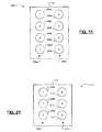
- FIGS. 2A-2B depict example firing orders for six and eight cylinder configurations of the V-engine according to the principles of the present disclosure.
- FIG. 3 depicts a flow diagram of an example method of cylinder deactivation control according to the principles of the present disclosure.
- Cylinder deactivation involves temporarily deactivating some of the cylinders (e.g., by closing their intake/exhaust valves using respective deactivation mechanisms) during low or light load operation.
- V4 four-cylinder
- V8 eight-cylinder
- V4 mode is typically incapable of achieving the engine's torque request across a wide range of operating conditions, e.g., above 45 miles per hour.
- the fuel economy benefit from this V4/V8 cylinder deactivation system is far from optimal.
- Implementing deactivation mechanism(s) on each of the 8 cylinders would provide for dynamic cylinder deactivation control.
- Such a configuration would be costly due to the requirement of 8 deactivation mechanisms and it would be very complex to determine the optimal deactivation schemes. Accordingly, there remains a need for an improvement in the art of cylinder deactivation systems.
- the engine system 104 comprises an engine 108 that combusts an air/fuel mixture to generate drive torque and a controller 112 that controls operation of the engine 108 .
- the engine 108 draws air into an intake manifold 116 through an induction system 120 that is regulated by a throttle valve 124 .
- the air in the intake manifold is combined with fuel from fuel injectors 128 and the air/fuel mixture is combusted within a plurality of cylinders 132 .
- the engine 108 is a V-engine having its X cylinders evenly distributed between two distinct cylinder banks.
- Each cylinder 132 comprises a respective intake and exhaust valve 136 , 140 that are selectively deactivated by a respective deactivation mechanism 144 .
- a non-limiting example of the deactivation mechanisms 144 is one or more solenoids (e.g., one solenoid for both valves 136 , 140 or one solenoid per valve 136 , 140 ).
- the air/fuel supply to the cylinders 132 is disabled.
- each cylinder 132 may also have a respective spark plug for igniting the air/fuel mixture therein.
- Exhaust gas resulting from combustion is expelled via the exhaust valves 140 and treated by an exhaust system 148 before being released into the atmosphere.
- the combustion of the air/fuel mixture within the cylinders 132 drives respective pistons (not shown), which rotatably turn a crankshaft 152 .
- the drive torque is transferred from the crankshaft 152 to a driveline 156 via a transmission 160 .
- One or more sensors 164 are utilized by the controller 112 to monitor operating parameters of the vehicle 100 , such as, but not limited to, accelerator pedal position, throttle valve position, intake mass air flow (MAF), intake MAP, intake/exhaust valve positions, as well as other speeds and temperatures (crankshaft speed, transmission output shaft or vehicle speed, air/exhaust gas temperatures, etc.).
- the controller 112 is also configured to perform at least a portion cylinder deactivation techniques as described in greater detail later herein. It will be appreciated, however, that at least a portion of the techniques (e.g., optimizing the placement of the Y DMs) could be performed by another computing system prior to vehicle assembly.
- FIGS. 2A-2B two example configurations 220 , 220 for the engine 108 are illustrated.
- FIG. 2A illustrates a V-engine 200 configuration comprising eight cylinders 204 a . . . 204 h arranged in first and second cylinder banks 208 a , 208 b .
- a sequential firing order for this particular V-engine configuration 200 is also illustrated ( 1 , 2 , . . . , 8 ), which does not correspond to a conventional numbering or labeling of the cylinders.
- FIG. 2B illustrates another V-engine 220 configuration comprising six cylinders 224 a . . . 224 f arranged in first and second cylinder banks 228 a , 228 b .
- a sequential firing order for this particular V-engine configuration 220 is also illustrated ( 1 , 2 , . . . , 6 ). As shown, an optimal firing order often alternates between cylinder banks 208 , 228 for balancing, e.g., to mitigate noise/vibration/harshness (NVH).
- NVH noise/vibration/harshness
- the cylinder deactivation mechanisms 144 are implemented for less than all of the cylinders and in optimal positions for each configuration 200 , 220 as discussed in greater detail below. In doing so, component and implementation costs are decreased while achieving performance (e.g., fuel economy) at or near the level achievable using cylinder activation mechanisms for all of the cylinders.
- integer variables X, Y, and Z are also utilized herein to describe the number of cylinders in the engine (X), the number of cylinders having deactivation mechanisms associated therewith (Y, where Y ⁇ X), and the number of cylinders to be deactivated (Z, where 0 ⁇ Z ⁇ Y) for a particular torque request (e.g., based on accelerator pedal position).
- Number of Patterns 2 X , where X is the number of cylinders as previously mentioned.
- X is the number of cylinders as previously mentioned.
- the average number of fired cylinders per engine cycle can be normalized by dividing the average number of by the cylinder count, thereby yielding a ratio of fired cylinders between 0 and 1, inclusive.
- a binary value of 0 (skip) or 1 (fire) could also be assigned to each cylinder for a particular firing order, e.g., no fires for a six cylinder configuration could be represented as 000000.
- N Fires Fires*( X/Ops )
- N Skips X ⁇ N Fires
- Skips Floor ⁇ Skips ⁇ Skips Ceiling Ceiling( N Skips/ N Fires)
- Fires Floor ⁇ Fires ⁇ Fires Ceiling where Fires represents the number of consecutive fires between skips
- the Floor function rounds the fractions down to the nearest multiple of significance, which in this case is the nearest integer value.
- the Ceiling function similarly rounds the fractions up to the nearest integer values.
- the most equally spaced (MES) patterns for any firing fraction FF can be determined.
- the simplified firing fraction is 1 ⁇ 3 (from 2/6).
- the number of MES patterns minimum (6/GCD(6,2), 6+1) or the minimum(3,7), which equals 3.
- the optimal configurations represent those having the greatest number of firing fractions FF and the largest spread of operating fractions, thereby allowing for the most broad reduction of pumping losses and the smallest fraction step size and allowing for smoother transitions between operating points.
- moving from 3 deactivation mechanisms (DMs) to 4 DMs adds the 2/3 firing fraction FF operating point, which could be desirable for low load, high vehicle speed scenarios (e.g., highway driving at approximately 70 miles per hour, or mph).
- the 5 DM solution is also much easier to implement as there are only 7 firing fraction FF operating points compared to 19 for the 6 DM solution.
- the above can be extended to the eight cylinder configuration 200 of FIG. 2A .
- the relevant data, including the number of firing fractions FF and the # of MES patterns are summarized in Table 3 below. As shown, moving from 4 to 5 DMs adds the 5/8 firing fraction FF operating point, which could be suitable for low load, high vehicle speed scenarios (e.g., highway driving at ⁇ 70 mph). Even better, however, is 6 DMs, which adds the 1/4 firing fraction FF operating point, as this is better suited for low load, low vehicle speed scenarios (e.g., neighborhood driving at ⁇ 25 mph).
- the 6 DM solution is also much easier to implement, as there are only 7 firing fraction FF operating points compared to 29 for the 8 DM solution.
- the controller 304 determines a torque target for the engine 108 , which could be based on a torque request as interpreted from an accelerator pedal position.
- the controller 112 determines whether the torque achievable by the engine 108 times a corresponding fraction (1 ⁇ 4) exceeds the torque target. This fraction, for example, corresponds to the firing fraction FF operating point currently being analyzed. If true, the controller 112 determines whether such operation would satisfy NVH thresholds at 312 .
- the engine 108 may be able to achieve the torque target at a particular firing fraction FF operating point, but doing so could result in excess vibration that would not satisfy the NVH thresholds. If these NVH thresholds are satisfied, however, the controller 112 proceeds to 316 and utilizes the particular firing fraction FF operating point (1 ⁇ 4). If the NVH thresholds are not satisfied, however, the method 300 proceeds to 320 where the next firing fraction FF operating point (1 ⁇ 2) is analyzed and so on and so forth at steps 320 - 380 . If no partial firing configuration is able to satisfy the torque and NVH thresholds, the controller 112 can operate the engine 108 using all X cylinders at 284 .
- controller 112 being able to determine the optimal firing fractions for specific hardware configurations.
- Implementing a deactivation mechanism on every cylinder is both costly from a hardware standpoint but also from a complexity and calibration standpoint. That is, the controller 112 would be required to run through many more possible firing fractions in order to determine which operating point to utilize for a particular torque request. This is expensive from both a time and computational resource perspective.
- the technical effect of these systems and methods is decreased costs through the use of deactivation mechanisms for less than all of the cylinders, as well as the optimal positioning of and quantity of deactivation mechanisms, which unexpectedly achieves the same or approximately the same performance (e.g., fuel economy) compared to deactivation mechanisms for every cylinder.
- controller refers to any suitable control device or set of multiple control devices that is/are configured to perform at least a portion of the techniques of the present disclosure.
- Non-limiting examples include an application-specific integrated circuit (ASIC), one or more processors and a non-transitory memory having instructions stored thereon that, when executed by the one or more processors, cause the controller to perform a set of operations corresponding to at least a portion of the techniques of the present disclosure.
- the one or more processors could be either a single processor or two or more processors operating in a parallel or distributed architecture.
- controller 112 is also described herein as performing at least a portion of the techniques, it will be appreciated that at least some of these activities could be performed by another system during design stages prior to vehicle assembly (e.g., the determination of the optimal hardware configuration).
Landscapes
- Engineering & Computer Science (AREA)
- Chemical & Material Sciences (AREA)
- Combustion & Propulsion (AREA)
- Mechanical Engineering (AREA)
- General Engineering & Computer Science (AREA)
- Output Control And Ontrol Of Special Type Engine (AREA)
Abstract
Description
Number of Patterns=2X,
where X is the number of cylinders as previously mentioned. For the six
Firing Fraction(FF)=(Fires/Ops),
where Fires represents the number of firings (0≤Fires≤Ops, 0≤FF≤1), Ops represents the number of firing opportunities, and Skips equals the difference between Ops and Fires (Skips=Ops−Fires).
Number of Patterns=(X!/(Fires!×Skips!))=(X!/(Fires!×(X-Fires)!)).
| TABLE 1 | ||
| Decimal | Binary | Cylinder |
| Value | Value |
| 1 | 2 | 3 | 4 | 5 | 6 | |
| 3 | 000011 | 0 | 0 | 0 | 0 | 1 | 1 |
| 5 | 000101 | 0 | 0 | 0 | 1 | 0 | 1 |
| 6 | 000110 | 0 | 0 | 0 | 1 | 1 | 0 |
| 9 | 001001 | 0 | 0 | 1 | 0 | 0 | 1 |
| 10 | 001010 | 0 | 0 | 1 | 0 | 1 | 0 |
| 12 | 001100 | 0 | 0 | 1 | 1 | 0 | 0 |
| 17 | 010001 | 0 | 1 | 0 | 0 | 0 | 1 |
| 18 | 010010 | 0 | 1 | 0 | 0 | 1 | 0 |
| 20 | 010100 | 0 | 1 | 0 | 1 | 0 | 0 |
| 24 | 011000 | 0 | 1 | 1 | 0 | 0 | 0 |
| 33 | 100001 | 1 | 0 | 0 | 0 | 0 | 1 |
| 34 | 100010 | 1 | 0 | 0 | 0 | 1 | 0 |
| 36 | 100100 | 1 | 0 | 0 | 1 | 0 | 0 |
| 40 | 101000 | 1 | 0 | 1 | 0 | 0 | 0 |
| 48 | 110000 | 1 | 1 | 0 | 0 | 0 | 0 |
NFires=Fires*(X/Ops),
NSkips=X−NFires, and
Skips Floor≤Skips≤Skips Ceiling,
where Skips represents the number of consecutive skips between fires. Utilizing the above:
Skips Floor=Floor(NSkips/NFires) and
Skips Ceiling=Ceiling(NSkips/NFires), where 1≤NFires≤X,
Skips Floor=X−1,Skips Ceiling=X, where 0<NFires<1, and
Skips Floor=Skips Ceiling=X, where NFires=0.
Fires Floor≤Fires≤Fires Ceiling, where Fires represents the number of consecutive fires between skips,
Fires Floor=Floor(NFires/NSkips) and
Fires Ceiling=Ceiling(NFires/NSkips), where 0<NFires<X−1,
Fires Floor=X−1 and Fires Ceiling=X, where X−1<NFires<X, and
Fires Floor=Fires Ceiling=X, where NFires=X.
Simplified Denominator=Denominator/GCD(Denominator,Numerator),
Number of MES Patterns=Minimum(Simplified Denominator,X+1).
| TABLE 2 | ||||
| Y | DM Position(s) | # of FF | FF | # of |
| 1 | 1 | 2 | 1, ⅚ | 2 |
| 2 | 1 (2, 3, 5, or 6) | 2 | 1, ⅚ | 3 or 4 |
| 2 | 1, 4 | 3 | 1, ⅚, ⅔ | 4 |
| 3 | 1, 3, 5 | 4 | 1, ⅚, ¾, ½ | 7 |
| 4 | 1, 3, 4, 5 | 5 | 1, ⅚, ¾, ⅔, ½ | 10 |
| 5 | 1, 2, 3, 4, 5 | 7 | 1, ⅚, ¾, ⅔, ½, ⅓, ⅙ | 18 |
| 6 | 1, 2, 3, 4, 5, 6 | 19 | 1, 6/7, ⅚, ⅘, ¾, 5/7, ⅔, ⅗, 4/7, | 36 |
| ½, 3/7, ⅖, ⅓, 2/7, ¼, ⅕, ⅙, 1/7, 0 | ||||
| TABLE 3 | ||||
| Y | DM Position(s) | # of FF | FF | # of MES Patterns |
| 1 | 1 | 2 | 1, ⅞ | 2 |
| 2 | 1 (2, 3, 4, 6, 7, or 8) | 2 | 1, ⅞ | 3 or 4 |
| 2 | 1, 5 | 3 | 1, ⅞, ¾ | 4 |
| 3 | 1, 3, 6 | 3 | 1, ⅞, ⅝ | 6 or 7 |
| 4 | 1, 3, 5, 7 | 5 | 1, ⅞, ⅚, ¾, ½ | 10 |
| 5 | 1, 2, 3, 5, 7 | 6 | 1, ⅞, ⅚, ¾, ⅝, ½ | 13, 14, 15, or 17 |
| 6 | 1, 2, 3, 5, 6, 7 | 7 | 1, ⅞, ⅚, ¾, ⅝, ½, ¼ | 22 or 23 |
| 7 | 1, 2, 3, 4, 5, 6, 7 | 9 | 1, ⅞, ⅚, ¾, ⅝, ½, ⅜, ¼, ⅛ | 38 |
| 8 | 1, 2, 3, 4, 5, | 29 | 1, 8/9, ⅞, 6/7, ⅚, ⅘, 7/9, ¾, 5/7, | 76 |
| 6, 7, 8 | ⅔, ⅝, ⅗, 4/7, 5/9, ½, 4/9, 3/7, ⅖, | |||
| ⅜, ⅓, 2/7, ¼, 2/9, ⅕, ⅙, 1/7, ⅛, 1/9, 0 | ||||
As can be seen, moving from 6 DMs to 7 DMs only adds the 1/8 and 3/8 firing fraction FF operating points, which may not provide much if any benefit over the 1/4 firing fraction FF operating point. The 6 DM solution is also much easier to implement, as there are only 7 firing fraction FF operating points compared to 29 for the 8 DM solution. Referring to the eight
Claims (19)
Priority Applications (1)
| Application Number | Priority Date | Filing Date | Title |
|---|---|---|---|
| US15/655,416 US10443518B2 (en) | 2017-07-20 | 2017-07-20 | Optimal firing patterns for cylinder deactivation control with limited deactivation mechanisms |
Applications Claiming Priority (1)
| Application Number | Priority Date | Filing Date | Title |
|---|---|---|---|
| US15/655,416 US10443518B2 (en) | 2017-07-20 | 2017-07-20 | Optimal firing patterns for cylinder deactivation control with limited deactivation mechanisms |
Publications (2)
| Publication Number | Publication Date |
|---|---|
| US20190024594A1 US20190024594A1 (en) | 2019-01-24 |
| US10443518B2 true US10443518B2 (en) | 2019-10-15 |
Family
ID=65018461
Family Applications (1)
| Application Number | Title | Priority Date | Filing Date |
|---|---|---|---|
| US15/655,416 Active 2038-01-09 US10443518B2 (en) | 2017-07-20 | 2017-07-20 | Optimal firing patterns for cylinder deactivation control with limited deactivation mechanisms |
Country Status (1)
| Country | Link |
|---|---|
| US (1) | US10443518B2 (en) |
Families Citing this family (3)
| Publication number | Priority date | Publication date | Assignee | Title |
|---|---|---|---|---|
| US11549455B2 (en) * | 2019-04-08 | 2023-01-10 | Tula Technology, Inc. | Skip cylinder compression braking |
| EP4018086A4 (en) * | 2019-08-22 | 2023-09-27 | Purdue Research Foundation | METHOD FOR DYNAMIC DETERMINATION OF AN IGNITION PATTERN FOR AN ENGINE WITH DYNAMIC CYLINDER ACTUATION |
| CN115841047A (en) * | 2023-02-13 | 2023-03-24 | 潍柴动力股份有限公司 | Screening method and device for engine balanced major cycle and storage medium |
Citations (14)
| Publication number | Priority date | Publication date | Assignee | Title |
|---|---|---|---|---|
| US4509488A (en) | 1981-07-23 | 1985-04-09 | Daimler-Benz Aktiengesellschaft | Process and apparatus for intermittent control of a cyclically operating internal combustion engine |
| US7577511B1 (en) | 2008-07-11 | 2009-08-18 | Tula Technology, Inc. | Internal combustion engine control for improved fuel efficiency |
| US20130092127A1 (en) * | 2011-10-17 | 2013-04-18 | Tula Technology, Inc. | Firing fraction management in skip fire engine control |
| US8464690B2 (en) | 2008-07-11 | 2013-06-18 | Tula Technology, Inc. | Hybrid vehicle with cylinder deactivation |
| US8880258B2 (en) | 2011-10-17 | 2014-11-04 | Tula Technology, Inc. | Hybrid powertrain control |
| US8892330B2 (en) | 2011-10-17 | 2014-11-18 | Tula Technology, Inc. | Hybrid vehicle with cylinder deactivation |
| US9200575B2 (en) | 2013-03-15 | 2015-12-01 | Tula Technology, Inc. | Managing engine firing patterns and pattern transitions during skip fire engine operation |
| US9212610B2 (en) | 2013-03-15 | 2015-12-15 | Tula Technology, Inc. | Engine diagnostics with skip fire control |
| US9239024B2 (en) | 2012-09-10 | 2016-01-19 | GM Global Technology Operations LLC | Recursive firing pattern algorithm for variable cylinder deactivation in transient operation |
| US20160053697A1 (en) | 2011-10-17 | 2016-02-25 | Tula Technology, Inc. | Skip fire transition control |
| US20160201586A1 (en) * | 2015-01-12 | 2016-07-14 | Tula Technology, Inc. | Noise, vibration and harshness reduction in a skip fire engine control system |
| US9458778B2 (en) | 2012-08-24 | 2016-10-04 | GM Global Technology Operations LLC | Cylinder activation and deactivation control systems and methods |
| US20170218866A1 (en) * | 2014-05-12 | 2017-08-03 | Tula Technology, Inc. | Internal combustion engine air charge control |
| US20170370308A1 (en) * | 2016-06-23 | 2017-12-28 | Tula Technology, Inc. | Dynamic skip fire operation of a gasoline compression ignition engine |
Family Cites Families (1)
| Publication number | Priority date | Publication date | Assignee | Title |
|---|---|---|---|---|
| CN103499904B (en) * | 2013-10-25 | 2016-06-22 | 北京京东方光电科技有限公司 | Display floater and preparation method thereof, display device |
-
2017
- 2017-07-20 US US15/655,416 patent/US10443518B2/en active Active
Patent Citations (14)
| Publication number | Priority date | Publication date | Assignee | Title |
|---|---|---|---|---|
| US4509488A (en) | 1981-07-23 | 1985-04-09 | Daimler-Benz Aktiengesellschaft | Process and apparatus for intermittent control of a cyclically operating internal combustion engine |
| US8464690B2 (en) | 2008-07-11 | 2013-06-18 | Tula Technology, Inc. | Hybrid vehicle with cylinder deactivation |
| US7577511B1 (en) | 2008-07-11 | 2009-08-18 | Tula Technology, Inc. | Internal combustion engine control for improved fuel efficiency |
| US20160053697A1 (en) | 2011-10-17 | 2016-02-25 | Tula Technology, Inc. | Skip fire transition control |
| US8880258B2 (en) | 2011-10-17 | 2014-11-04 | Tula Technology, Inc. | Hybrid powertrain control |
| US8892330B2 (en) | 2011-10-17 | 2014-11-18 | Tula Technology, Inc. | Hybrid vehicle with cylinder deactivation |
| US20130092127A1 (en) * | 2011-10-17 | 2013-04-18 | Tula Technology, Inc. | Firing fraction management in skip fire engine control |
| US9458778B2 (en) | 2012-08-24 | 2016-10-04 | GM Global Technology Operations LLC | Cylinder activation and deactivation control systems and methods |
| US9239024B2 (en) | 2012-09-10 | 2016-01-19 | GM Global Technology Operations LLC | Recursive firing pattern algorithm for variable cylinder deactivation in transient operation |
| US9200575B2 (en) | 2013-03-15 | 2015-12-01 | Tula Technology, Inc. | Managing engine firing patterns and pattern transitions during skip fire engine operation |
| US9212610B2 (en) | 2013-03-15 | 2015-12-15 | Tula Technology, Inc. | Engine diagnostics with skip fire control |
| US20170218866A1 (en) * | 2014-05-12 | 2017-08-03 | Tula Technology, Inc. | Internal combustion engine air charge control |
| US20160201586A1 (en) * | 2015-01-12 | 2016-07-14 | Tula Technology, Inc. | Noise, vibration and harshness reduction in a skip fire engine control system |
| US20170370308A1 (en) * | 2016-06-23 | 2017-12-28 | Tula Technology, Inc. | Dynamic skip fire operation of a gasoline compression ignition engine |
Also Published As
| Publication number | Publication date |
|---|---|
| US20190024594A1 (en) | 2019-01-24 |
Similar Documents
| Publication | Publication Date | Title |
|---|---|---|
| US9239024B2 (en) | Recursive firing pattern algorithm for variable cylinder deactivation in transient operation | |
| US9458780B2 (en) | Systems and methods for controlling cylinder deactivation periods and patterns | |
| US9416743B2 (en) | Cylinder activation/deactivation sequence control systems and methods | |
| US9441550B2 (en) | Cylinder firing fraction determination and control systems and methods | |
| US8573184B2 (en) | Control apparatus for controlling intake air flow, fuel injection amount, and ignition timing at each cylinder of a multi-cylinder engine | |
| US9556811B2 (en) | Firing pattern management for improved transient vibration in variable cylinder deactivation mode | |
| US10443518B2 (en) | Optimal firing patterns for cylinder deactivation control with limited deactivation mechanisms | |
| CN104047736B (en) | For balancing phase shifter control system and the method for mean effective pressure | |
| US9605567B2 (en) | Oil pump control systems and methods | |
| US9701299B2 (en) | System and method for controlling an engine based on a desired turbine power to account for losses in a torque converter | |
| US10760479B2 (en) | Turbocharger surge management control techniques to eliminate surge valve | |
| US10260438B2 (en) | Cylinder de-activation control method and cylinder de-activation system | |
| JP2018100658A (en) | Variable control method and variable control device of combustion cylinder ratio | |
| CN113107715A (en) | Dedicated exhaust gas recirculation control system and method | |
| CN103939220B (en) | For stoping the cylinder control system and method that resonant frequency operates | |
| US9605612B2 (en) | System and method for determining the speed of an engine when one or more cylinders of the engine are deactivated | |
| CN105526015B (en) | Asymmetric cylinder deactivation engine | |
| US11905899B2 (en) | Smart firing pattern selection for skip fire capable engines | |
| CN114312727A (en) | System and method for limiting engine torque and controlling clutch | |
| CN111520236B (en) | System and method for determining indicated mean effective pressure | |
| US11313291B2 (en) | Secondary throttle control systems and methods | |
| CN114320632A (en) | System and method for controlling air flow through engine cylinders during deceleration fuel cut events | |
| TH1801000137A (en) | Internal combustion engine systems and control methods for internal combustion engines |
Legal Events
| Date | Code | Title | Description |
|---|---|---|---|
| AS | Assignment |
Owner name: FCA US LLC, MICHIGAN Free format text: ASSIGNMENT OF ASSIGNORS INTEREST;ASSIGNOR:SHOST, MARK A;REEL/FRAME:043062/0030 Effective date: 20170706 |
|
| STPP | Information on status: patent application and granting procedure in general |
Free format text: NON FINAL ACTION MAILED |
|
| STPP | Information on status: patent application and granting procedure in general |
Free format text: RESPONSE TO NON-FINAL OFFICE ACTION ENTERED AND FORWARDED TO EXAMINER |
|
| STPP | Information on status: patent application and granting procedure in general |
Free format text: NOTICE OF ALLOWANCE MAILED -- APPLICATION RECEIVED IN OFFICE OF PUBLICATIONS |
|
| STPP | Information on status: patent application and granting procedure in general |
Free format text: PUBLICATIONS -- ISSUE FEE PAYMENT VERIFIED |
|
| STCF | Information on status: patent grant |
Free format text: PATENTED CASE |
|
| MAFP | Maintenance fee payment |
Free format text: PAYMENT OF MAINTENANCE FEE, 4TH YEAR, LARGE ENTITY (ORIGINAL EVENT CODE: M1551); ENTITY STATUS OF PATENT OWNER: LARGE ENTITY Year of fee payment: 4 |