US10437499B2 - Hybrid memory system and method of operating the same - Google Patents

Hybrid memory system and method of operating the same Download PDF

Info

Publication number
US10437499B2
US10437499B2 US15/900,013 US201815900013A US10437499B2 US 10437499 B2 US10437499 B2 US 10437499B2 US 201815900013 A US201815900013 A US 201815900013A US 10437499 B2 US10437499 B2 US 10437499B2
Authority
US
United States
Prior art keywords
valid data
memory
volatile memory
row
data
Prior art date
Legal status (The legal status is an assumption and is not a legal conclusion. Google has not performed a legal analysis and makes no representation as to the accuracy of the status listed.)
Active
Application number
US15/900,013
Other versions
US20190196733A1 (en
Inventor
Chung-Hsun Lee
Hsien-Wen Liu
Current Assignee (The listed assignees may be inaccurate. Google has not performed a legal analysis and makes no representation or warranty as to the accuracy of the list.)
Nanya Technology Corp
Original Assignee
Nanya Technology Corp
Priority date (The priority date is an assumption and is not a legal conclusion. Google has not performed a legal analysis and makes no representation as to the accuracy of the date listed.)
Filing date
Publication date
Application filed by Nanya Technology Corp filed Critical Nanya Technology Corp
Priority to US15/900,013 priority Critical patent/US10437499B2/en
Assigned to NANYA TECHNOLOGY CORPORATION reassignment NANYA TECHNOLOGY CORPORATION ASSIGNMENT OF ASSIGNORS INTEREST (SEE DOCUMENT FOR DETAILS). Assignors: LEE, CHUNG-HSUN, LIU, HSIEN-WEN
Priority to TW107123353A priority patent/TWI687929B/en
Priority to CN201810890246.9A priority patent/CN109960465B/en
Publication of US20190196733A1 publication Critical patent/US20190196733A1/en
Application granted granted Critical
Publication of US10437499B2 publication Critical patent/US10437499B2/en
Active legal-status Critical Current
Anticipated expiration legal-status Critical

Links

Images

Classifications

    • GPHYSICS
    • G06COMPUTING; CALCULATING OR COUNTING
    • G06FELECTRIC DIGITAL DATA PROCESSING
    • G06F3/00Input arrangements for transferring data to be processed into a form capable of being handled by the computer; Output arrangements for transferring data from processing unit to output unit, e.g. interface arrangements
    • G06F3/06Digital input from, or digital output to, record carriers, e.g. RAID, emulated record carriers or networked record carriers
    • G06F3/0601Interfaces specially adapted for storage systems
    • G06F3/0628Interfaces specially adapted for storage systems making use of a particular technique
    • G06F3/0629Configuration or reconfiguration of storage systems
    • G06F3/0634Configuration or reconfiguration of storage systems by changing the state or mode of one or more devices
    • GPHYSICS
    • G11INFORMATION STORAGE
    • G11CSTATIC STORES
    • G11C11/00Digital stores characterised by the use of particular electric or magnetic storage elements; Storage elements therefor
    • G11C11/21Digital stores characterised by the use of particular electric or magnetic storage elements; Storage elements therefor using electric elements
    • G11C11/34Digital stores characterised by the use of particular electric or magnetic storage elements; Storage elements therefor using electric elements using semiconductor devices
    • G11C11/40Digital stores characterised by the use of particular electric or magnetic storage elements; Storage elements therefor using electric elements using semiconductor devices using transistors
    • G11C11/401Digital stores characterised by the use of particular electric or magnetic storage elements; Storage elements therefor using electric elements using semiconductor devices using transistors forming cells needing refreshing or charge regeneration, i.e. dynamic cells
    • G11C11/406Management or control of the refreshing or charge-regeneration cycles
    • G11C11/40615Internal triggering or timing of refresh, e.g. hidden refresh, self refresh, pseudo-SRAMs
    • GPHYSICS
    • G06COMPUTING; CALCULATING OR COUNTING
    • G06FELECTRIC DIGITAL DATA PROCESSING
    • G06F3/00Input arrangements for transferring data to be processed into a form capable of being handled by the computer; Output arrangements for transferring data from processing unit to output unit, e.g. interface arrangements
    • G06F3/06Digital input from, or digital output to, record carriers, e.g. RAID, emulated record carriers or networked record carriers
    • G06F3/0601Interfaces specially adapted for storage systems
    • G06F3/0602Interfaces specially adapted for storage systems specifically adapted to achieve a particular effect
    • G06F3/0614Improving the reliability of storage systems
    • G06F3/0619Improving the reliability of storage systems in relation to data integrity, e.g. data losses, bit errors
    • GPHYSICS
    • G06COMPUTING; CALCULATING OR COUNTING
    • G06FELECTRIC DIGITAL DATA PROCESSING
    • G06F3/00Input arrangements for transferring data to be processed into a form capable of being handled by the computer; Output arrangements for transferring data from processing unit to output unit, e.g. interface arrangements
    • G06F3/06Digital input from, or digital output to, record carriers, e.g. RAID, emulated record carriers or networked record carriers
    • G06F3/0601Interfaces specially adapted for storage systems
    • G06F3/0602Interfaces specially adapted for storage systems specifically adapted to achieve a particular effect
    • G06F3/0625Power saving in storage systems
    • GPHYSICS
    • G06COMPUTING; CALCULATING OR COUNTING
    • G06FELECTRIC DIGITAL DATA PROCESSING
    • G06F3/00Input arrangements for transferring data to be processed into a form capable of being handled by the computer; Output arrangements for transferring data from processing unit to output unit, e.g. interface arrangements
    • G06F3/06Digital input from, or digital output to, record carriers, e.g. RAID, emulated record carriers or networked record carriers
    • G06F3/0601Interfaces specially adapted for storage systems
    • G06F3/0628Interfaces specially adapted for storage systems making use of a particular technique
    • G06F3/0646Horizontal data movement in storage systems, i.e. moving data in between storage devices or systems
    • G06F3/0647Migration mechanisms
    • GPHYSICS
    • G06COMPUTING; CALCULATING OR COUNTING
    • G06FELECTRIC DIGITAL DATA PROCESSING
    • G06F3/00Input arrangements for transferring data to be processed into a form capable of being handled by the computer; Output arrangements for transferring data from processing unit to output unit, e.g. interface arrangements
    • G06F3/06Digital input from, or digital output to, record carriers, e.g. RAID, emulated record carriers or networked record carriers
    • G06F3/0601Interfaces specially adapted for storage systems
    • G06F3/0628Interfaces specially adapted for storage systems making use of a particular technique
    • G06F3/0655Vertical data movement, i.e. input-output transfer; data movement between one or more hosts and one or more storage devices
    • G06F3/0659Command handling arrangements, e.g. command buffers, queues, command scheduling
    • GPHYSICS
    • G06COMPUTING; CALCULATING OR COUNTING
    • G06FELECTRIC DIGITAL DATA PROCESSING
    • G06F3/00Input arrangements for transferring data to be processed into a form capable of being handled by the computer; Output arrangements for transferring data from processing unit to output unit, e.g. interface arrangements
    • G06F3/06Digital input from, or digital output to, record carriers, e.g. RAID, emulated record carriers or networked record carriers
    • G06F3/0601Interfaces specially adapted for storage systems
    • G06F3/0668Interfaces specially adapted for storage systems adopting a particular infrastructure
    • G06F3/0671In-line storage system
    • G06F3/0673Single storage device
    • G06F3/068Hybrid storage device
    • GPHYSICS
    • G11INFORMATION STORAGE
    • G11CSTATIC STORES
    • G11C11/00Digital stores characterised by the use of particular electric or magnetic storage elements; Storage elements therefor
    • G11C11/21Digital stores characterised by the use of particular electric or magnetic storage elements; Storage elements therefor using electric elements
    • G11C11/34Digital stores characterised by the use of particular electric or magnetic storage elements; Storage elements therefor using electric elements using semiconductor devices
    • G11C11/40Digital stores characterised by the use of particular electric or magnetic storage elements; Storage elements therefor using electric elements using semiconductor devices using transistors
    • G11C11/401Digital stores characterised by the use of particular electric or magnetic storage elements; Storage elements therefor using electric elements using semiconductor devices using transistors forming cells needing refreshing or charge regeneration, i.e. dynamic cells
    • G11C11/406Management or control of the refreshing or charge-regeneration cycles
    • G11C11/40618Refresh operations over multiple banks or interleaving
    • GPHYSICS
    • G11INFORMATION STORAGE
    • G11CSTATIC STORES
    • G11C11/00Digital stores characterised by the use of particular electric or magnetic storage elements; Storage elements therefor
    • G11C11/21Digital stores characterised by the use of particular electric or magnetic storage elements; Storage elements therefor using electric elements
    • G11C11/34Digital stores characterised by the use of particular electric or magnetic storage elements; Storage elements therefor using electric elements using semiconductor devices
    • G11C11/40Digital stores characterised by the use of particular electric or magnetic storage elements; Storage elements therefor using electric elements using semiconductor devices using transistors
    • G11C11/401Digital stores characterised by the use of particular electric or magnetic storage elements; Storage elements therefor using electric elements using semiconductor devices using transistors forming cells needing refreshing or charge regeneration, i.e. dynamic cells
    • G11C11/406Management or control of the refreshing or charge-regeneration cycles
    • G11C11/40622Partial refresh of memory arrays
    • GPHYSICS
    • G11INFORMATION STORAGE
    • G11CSTATIC STORES
    • G11C14/00Digital stores characterised by arrangements of cells having volatile and non-volatile storage properties for back-up when the power is down
    • G11C14/0009Digital stores characterised by arrangements of cells having volatile and non-volatile storage properties for back-up when the power is down in which the volatile element is a DRAM cell
    • G11C14/0018Digital stores characterised by arrangements of cells having volatile and non-volatile storage properties for back-up when the power is down in which the volatile element is a DRAM cell whereby the nonvolatile element is an EEPROM element, e.g. a floating gate or metal-nitride-oxide-silicon [MNOS] transistor
    • GPHYSICS
    • G11INFORMATION STORAGE
    • G11CSTATIC STORES
    • G11C11/00Digital stores characterised by the use of particular electric or magnetic storage elements; Storage elements therefor
    • G11C11/21Digital stores characterised by the use of particular electric or magnetic storage elements; Storage elements therefor using electric elements
    • G11C11/34Digital stores characterised by the use of particular electric or magnetic storage elements; Storage elements therefor using electric elements using semiconductor devices
    • G11C11/40Digital stores characterised by the use of particular electric or magnetic storage elements; Storage elements therefor using electric elements using semiconductor devices using transistors
    • G11C11/401Digital stores characterised by the use of particular electric or magnetic storage elements; Storage elements therefor using electric elements using semiconductor devices using transistors forming cells needing refreshing or charge regeneration, i.e. dynamic cells
    • G11C11/406Management or control of the refreshing or charge-regeneration cycles
    • G11C11/40611External triggering or timing of internal or partially internal refresh operations, e.g. auto-refresh or CAS-before-RAS triggered refresh
    • GPHYSICS
    • G11INFORMATION STORAGE
    • G11CSTATIC STORES
    • G11C2211/00Indexing scheme relating to digital stores characterized by the use of particular electric or magnetic storage elements; Storage elements therefor
    • G11C2211/401Indexing scheme relating to cells needing refreshing or charge regeneration, i.e. dynamic cells
    • G11C2211/406Refreshing of dynamic cells
    • G11C2211/4067Refresh in standby or low power modes

Definitions

  • the present disclosure relates to a hybrid memory system and a method of operating the same, and more particularly, to a hybrid memory system including a volatile memory and a non-volatile memory.
  • DRAM Dynamic random access memory
  • NMOS N-type metal-oxide-semiconductor
  • a simplest DRAM cell comprises a single N-type metal-oxide-semiconductor (NMOS) transistor and a single capacitor. If charge is stored in the capacitor, the cell is said to store a logic HIGH, depending on the convention used. If no charge is present, the cell is said to store a logic LOW. Because the charge in the capacitor dissipates over time, DRAM systems require additional refreshing circuitries to periodically refresh the charge stored in the capacitors.
  • NMOS N-type metal-oxide-semiconductor
  • bit lines are typically used for each bit, wherein the first bit line in the bit line pair is known as a bit line true (BLT) and the other bit line in the bit line pair is the bit line complement (BLC).
  • BLT bit line true
  • BLC bit line complement
  • the single NMOS transistor's gate is controlled by a word line (WL). To maintain data integrity, it is required to perform a refresh operation, resulting in power consumption.
  • the hybrid memory system includes a non-volatile memory, a volatile memory and a controller.
  • the volatile memory is configured to store data.
  • the controller is configured to move the data from the volatile memory to the non-volatile memory in response to a command which requests to enter a power-saving mode.
  • the controller is configured to preclude the volatile memory from having a self-refresh operation performed thereon after the movement of the data.
  • the controller is further configured to move a valid data from the volatile memory to the non-volatile memory in response to the command.
  • the controller is further configured to preclude the volatile memory from having the self-refresh operation performed thereon after the movement of the valid data.
  • the controller is further configured to identify the valid data from the data.
  • the volatile memory includes a first refresh area and a second refresh area.
  • the first refresh area is configured to store a first quantity of a first valid data.
  • the second refresh area is configured to store a second quantity, less than the first quantity, of a second valid data.
  • the controller is further configured to move only the second valid data to the non-volatile memory in response to the command.
  • the controller is further configured to preclude the second refresh area from having a partial-self-refresh operation performed thereon after the movement of the second valid data.
  • the controller is further configured to allow the first refresh area to have the partial-self-refresh operation performed thereon after the movement of the second valid data.
  • the volatile memory includes a memory row.
  • the non-volatile memory is configured to store a valid data from the memory row in response to the command.
  • the controller is further configured to move the valid data from the non-volatile memory back to the volatile memory in response to a command to exit from the power-saving mode.
  • the memory row stores no valid data after the movement of the valid data hack to the volatile memory.
  • the controller is further configured to preclude the memory row from having a partial-self-refresh operation performed thereon after the movement of the valid data back to the volatile memory.
  • the volatile memory includes a first memory row and a second memory row.
  • the non-volatile memory is configured to store a first valid data from the first memory row and a second valid data from the second memory row in response to the command.
  • the controller is further configured to move the first valid data and the second valid data from the non-volatile memory back to the first memory row in response to a command to exit from the power-saving mode.
  • the controller is further configured to allow the first memory row to have a partial-self-refresh operation performed thereon and preclude the second memory row from having the partial-self-refresh operation performed thereon.
  • the controller is further configured to allow the first memory row to be accessed.
  • the hybrid memory system comprises a volatile memory and a non-volatile memory.
  • the volatile memory includes a first memory row and a second memory row.
  • the non-volatile memory is configured to store a first valid data from the first memory row and a second valid data from the second memory row in response to a command to enter a power-saving mode.
  • the controller is configured to, in response to a command to exit from the power-saving mode, move both the first valid data and the second valid data to the first memory row.
  • the controller is configured to preclude the second memory row, in response to the command, from being accessed for the second valid data.
  • the controller is further configured to preclude the second memory row from having the partial-self-refresh operation performed thereon.
  • the method comprises: storing data in a volatile memory; moving the data from the volatile memory to a non-volatile memory in response to a command to enter a power-saving mode; and precluding the volatile memory from having a self-refresh operation performed thereon after the movement of the data.
  • the method further comprises: storing a valid data in the volatile memory; moving the valid data from the volatile memory to the non-volatile memory in response to the command; and precluding the volatile memory from having a self-refresh operation performed thereon after the movement of the valid data.
  • the method further comprises: precluding the volatile memory from having the self-refresh operation performed thereon after the movement of the valid data.
  • the method further comprises: (1) storing a first quantity of a first valid data by a first refresh area; (2) storing a second quantity, less than the first quantity, of a second valid data by a second refresh area; (3) moving only the second valid data to the non-volatile memory in response to the command; and (4) precluding the second refresh area from having a partial-self-refresh operation performed thereon after the movement of the second valid data.
  • the method further comprises: allowing the first refresh area to have the partial-self-refresh operation performed thereon after the movement of the second valid data.
  • the method further comprises: storing a valid data from a memory row of the volatile memory in the non-volatile memory in response to the command; moving the valid data from the non-volatile memory back to the volatile memory in response to a command to exit from the power-saving mode; and precluding the memory row from having the partial-self-refresh operation performed thereon after the movement of the valid data back to the volatile memory, wherein the memory row stores no valid data after the movement of the valid data back to the volatile memory.
  • the method further comprises: precluding the memory row from being accessed for the valid data after the movement of the valid data back to the volatile memory.
  • the method further comprises: storing a first valid data from a first memory row of the volatile memory in the non-volatile memory in response to the command; storing a second valid data from a second memory row of the volatile memory in the non-volatile memory in response to the command; moving the first valid data and the second valid data from the non-volatile memory back to the first memory row in response to a command to exit from the power-saving mode; and allowing the first memory row to have a partial-self-refresh operation performed thereon and precluding the second memory row from having the partial-self-refresh operation performed thereon after the movement of the first valid data and the second valid data back to the first memory row.
  • FIG. 1 is a schematic diagram of a hybrid memory system, in accordance with some embodiments of the present disclosure.
  • FIG. 2 is a flow chart of a method of operating a hybrid memory system, in accordance with some embodiments of the present disclosure.
  • FIG. 3 is a schematic diagram of the hybrid memory system shown in FIG. 1 in a scenario, in accordance with some embodiments of the present disclosure.
  • FIG. 4 is a schematic diagram illustrating a movement operation from the volatile memory to the non-volatile memory in the scenario of FIG. 3 , in accordance with some embodiments of the present disclosure.
  • FIG. 5 is a schematic diagram illustrating a disabling operation in the scenario of FIG. 3 , in accordance with some embodiments of the present disclosure.
  • FIG. 6 is a flow chart of another method of operating a hybrid memory system, in accordance with some embodiments of the present disclosure.
  • FIG. 7 is a schematic diagram of the hybrid memory system shown in FIG. 1 in another scenario, in accordance with some embodiments of the present disclosure.
  • FIG. 8 is a schematic diagram illustrating a movement operation from the volatile memory to the non-volatile memory in the scenario of FIG. 7 , in accordance with some embodiments of the present disclosure.
  • FIG. 9 is a schematic diagram illustrating a disabling operation in the scenario of FIG. 7 , in accordance with some embodiments of the present disclosure.
  • FIG. 10 is a schematic diagram illustrating a partial-self-refresh operation in the scenario of FIG. 7 , in accordance with some embodiments of the present disclosure.
  • FIG. 11 is a flow chart of yet another method of operating a hybrid memory system, in accordance with some embodiments of the present disclosure.
  • FIG. 12 is a schematic diagram illustrating another movement operation from the non-volatile memory to the volatile memory, in accordance with some embodiments of the present disclosure.
  • FIG. 13 is a schematic diagram illustrating another refresh operation, in accordance with some embodiments of the present disclosure.
  • FIG. 14 is a schematic diagram illustrating an access operation of the hybrid memory system shown in FIG. 1 , in accordance with some embodiments of the present disclosure.
  • FIG. 15 is a flow chart of still another method of operating a hybrid memory system, in accordance with some embodiments of the present disclosure.
  • first, second, third, etc. may be used herein to describe various elements, components, regions, layers or sections, these elements, components, regions, layers or sections are not limited by these terms. Rather, these terms are merely used to distinguish one element, component, region, layer or section from another region, layer or section. Thus, a first element, component, region, layer or section discussed below could be termed a second element, component, region, layer or section without departing from the teachings of the present inventive concept.
  • FIG. 1 is a schematic diagram of a hybrid memory system 10 , in accordance with some embodiments of the present disclosure.
  • the hybrid memory system 10 includes a non-volatile memory 12 , a volatile memory 14 , a refresh device 16 , an access device 17 and a controller 18 .
  • the hybrid memory system 10 is integrated in a device, and enclosed in a housing.
  • the present disclosure is not limited thereto.
  • the non-volatile memory 12 functions to store data.
  • the non-volatile memory 12 includes a NAND flash memory.
  • the non-volatile memory 12 includes a read-only memory (ROM), a programmable read-only memory (PROM), an electrically alterable read-only memory (EAROM), an erasable programmable read-only memory (EPROM), or an electrically erasable programmable read-only memory (EEPROM).
  • ROM read-only memory
  • PROM programmable read-only memory
  • EAROM electrically alterable read-only memory
  • EPROM erasable programmable read-only memory
  • EEPROM electrically erasable programmable read-only memory
  • the volatile memory 14 functions to store data.
  • the volatile memory 14 includes a dynamic random access memory (DRAM).
  • the volatile memory 14 includes a memory array.
  • the memory array includes a plurality of memory cells 140 .
  • the memory cell 140 functions to store data.
  • the memory array further includes a plurality of word lines WL 1 to WLn and a plurality of bit lines BL 1 to BLm, wherein n and m are positive integers.
  • the word lines WL 1 to WLn and the bit lines BL 1 to BLm are used to control operation of the associated memory cells 140 .
  • the memory cells 140 in a single row and a word line for accessing those memory cells 140 can together be deemed as a memory row.
  • the present disclosure is not limited thereto.
  • the refresh device 16 functions to perform a self-refresh operation on the volatile memory 14 .
  • the self-refresh operation refers to the procedure in which the refresh device 16 automatically executes a refresh operation by, for example, using an internal refresh counter. There is no need for the refresh device 16 to obtain refresh request from, for example, a processor external to the hybrid memory system 10 to perform the self-refresh operation.
  • the refresh device 16 and/or other devices in the hybrid memory system 10 can generate, on their own, any information required to perform the self-refresh operation.
  • the refresh device 16 refreshes the volatile memory 14 in a fashion in which, for example, a charge is read from the memory cell 140 , and the charge is immediately written hack to the memory cell 140 .
  • the refresh operation may further include other detailed operations.
  • the access device 17 connected to the refresh device 16 and the volatile memory 14 , functions to access the volatile memory 14 to obtain the data stored in the volatile memory 14 , in particular, the memory cell 140 .
  • the controller 18 connected to the refresh device 16 and the non-volatile memory 12 , functions to control the refresh device 16 and the access device 17 .
  • the controller 18 functions to control a movement of a data between the non-volatile memory 12 and the volatile memory 14 .
  • the controller 18 receives a command to enter a power-saving mode, and, in response to the command, moves data stored in the volatile memory 14 from the volatile memory 14 to the nonvolatile memory 12 .
  • a refresh device is required to perform a self-refresh operation on a volatile memory to maintain data integrity.
  • the controller 18 precludes the volatile memory 14 from having the self-refresh operation performed thereon after the movement of the data and in particular in the power-saving mode.
  • FIG. 2 is a flow chart of a method 20 of operating a hybrid memory system, in accordance with some embodiments of the present disclosure. Referring to FIG. 2 , the method 20 includes operations 22 and 24 .
  • the method 20 begins with operation 22 , in which data stored in a volatile memory is moved from the volatile memory to a non-volatile memory in response to a command to enter a power-saving mode.
  • the method 20 proceeds to operation 24 , in which the volatile memory is precluded from having a self-refresh operation performed thereon after the movement of the data and in particular in the power-saving mode.
  • the method 20 is merely an example, and is not intended to limit the present disclosure beyond what is explicitly recited in the claims. Additional operations can be provided before, during, and after the method 20 , and some operations described can be replaced, eliminated, or moved around for additional embodiments of the method.
  • power consumption of a hybrid memory system adopting the method 20 is relatively efficient in a power-saving mode.
  • FIG. 3 is a schematic diagram of the hybrid memory system 10 shown in FIG. 1 in a scenario, in accordance with some embodiments of the present disclosure.
  • the volatile memory 14 stores a data including a valid data 140 and an invalid data 142 .
  • the valid data 140 refers to data which will be used by the controller 18 or an external processor (not shown) electrically connected to the hybrid memory system 10 .
  • the invalid data 142 refers to data which will not be used.
  • the present disclosure is not limited thereto. In other embodiments, there may be another appropriate basis on which to classify a valid data and an invalid data.
  • the controller 18 identifies the valid data 140 from the data according to the information provided by the external processor.
  • FIG. 4 is a schematic diagram illustrating a movement operation from the volatile memory 14 to the non-volatile memory 12 in the scenario of FIG. 3 , in accordance with some embodiments of the present disclosure.
  • the controller 18 moves the valid data 140 from the volatile memory 14 to the non-volatile memory 12 in response to the command.
  • FIG. 5 is a schematic diagram illustrating a disabling operation in the scenario of FIG. 3 , in accordance with some embodiments of the present disclosure.
  • the controller 18 precludes the volatile memory 14 from having the self-refresh operation performed thereon after the movement of the valid data 140 and in particular in the power-saving is mode.
  • FIG. 6 is a flow chart of another method 30 of operating a hybrid memory system, in accordance with some embodiments of the present disclosure.
  • the method 30 includes operations 32 , 34 and 36 .
  • the method 30 begins with operation 32 , in which a valid data is identified from data stored in a volatile memory.
  • the method 30 proceeds to operation 34 , in which the valid data is moved from the volatile memory to a non-volatile memory in response to a command to enter a power-saving mode.
  • the method 30 continues with operation 36 , in which the volatile memory without the valid data is precluded from having a self-refresh operation performed thereon after the movement of the valid data and in particular in the power-saving mode.
  • the method 30 is merely an example, and is not intended to limit the present disclosure beyond what is explicitly recited in the claims. Additional operations can be provided before, during, and after the method 30 , and some operations described can be replaced, eliminated, or moved around for additional embodiments of the method.
  • power consumption of a hybrid memory system adopting the method 30 is relatively efficient in a power-saving mode.
  • FIG. 7 is a schematic diagram of the hybrid memory system 10 shown in FIG. 1 in another scenario, in accordance with some embodiments of the present disclosure.
  • the volatile memory 14 includes a first refresh area 40 and a second refresh area 42 .
  • the first refresh area 40 stores first valid data 400 , 402 and 404 . Such quantity of the valid data only serves as an example.
  • the first refresh area 40 includes a plurality of memory rows. However, the present disclosure is not limited thereto.
  • the first refresh area 40 includes a single memory row.
  • the memory rows of the first refresh area 40 belong to a single bank. However, the present disclosure is not limited thereto.
  • the memory rows may belong to different banks. That is, the first refresh area 40 may include a single bank, a plurality of banks, a single memory row, or a plurality of memory rows. The present disclosure is not limited to any specific type as previously mentioned.
  • the second refresh area 42 stores second valid data 420 and 422 . That is, a second quantity of the second valid data is less than the first quantity of the first valid data. Such quantity of valid data only serves as an example.
  • the second refresh area 42 includes a plurality of memory rows. However, the present disclosure is not limited thereto. In some embodiments, the second refresh area 42 includes a single memory row. Moreover, in some embodiments, the memory rows of the second refresh area 42 belong to a single bank. However, the present disclosure is not limited thereto. The memory rows may belong to different banks. That is, the second refresh area 42 may include a single bank, a plurality of banks, a single memory row, or a plurality of memory rows. The present disclosure is not limited to any specific type as previously mentioned.
  • the controller 18 determines that the second quantity is less than the first quantity according to a storing data record which is maintained by the information from the external processor.
  • FIG. 8 is a schematic diagram illustrating a movement operation from the volatile memory 14 to the non-volatile memory 12 in the scenario of FIG. 7 , in accordance with some embodiments of the present disclosure.
  • the controller 18 moves only the second valid data 420 and 422 (i.e., moves the lesser second quantity) to the non-volatile memory 12 in response to the command.
  • FIG. 9 is a schematic diagram illustrating a disabling operation in the scenario of FIG. 7 , in accordance with some embodiments of the present disclosure.
  • the controller 18 disables the second refresh area 42 whose valid data 420 and 422 was moved to the non-volatile memory 12 .
  • FIG. 10 is a schematic diagram illustrating a partial-self-refresh operation in the scenario of FIG. 7 , in accordance with some embodiments of the present disclosure.
  • the controller 18 by disabling the second refresh area 42 , the controller 18 precludes the second refresh area 42 from having a partial-self-refresh operation performed thereon after the movement of the second valid data 420 and 422 .
  • the controller 14 allows the first refresh area 40 to have the partial-self-refresh operation performed thereon to maintain data integrity of the first valid data 400 , 402 and 404 .
  • FIG. 11 is a flow chart of yet another method 50 of operating a hybrid memory system, in accordance with some embodiments of the present disclosure.
  • the method 50 includes operations 52 , 54 , 56 and 58 .
  • the method 50 begins with operation 52 , in which a valid data is identified from data stored in each of a first refresh area and a second refresh area.
  • the method 50 proceeds to operation 54 , in which it is determined that the first refresh area stores a greater quantity of valid data than the second refresh area.
  • the method 50 continues with operation 56 , in which the valid data is moved from the second refresh area to a non-volatile memory in response to a command to enter a power-saving mode.
  • the method 50 continues with operation 58 , in which the second refresh area is precluded from having a partial-self-refresh operation performed thereon after the movement of the valid data.
  • the method 50 is merely an example, and is not intended to limit the present disclosure beyond what is explicitly recited in the claims. Additional operations can be provided before, during, and after the method 50 , and some operations described can be replaced, eliminated, or moved around for additional embodiments of the method.
  • power consumption of a hybrid memory system adopting the method 50 is relatively efficient in a power-saving mode.
  • FIG. 12 is a schematic diagram illustrating another movement operation from the non-volatile memory 12 to the volatile memory 14 , in accordance with some embodiments of the present disclosure. Operations described and illustrated with reference to FIGS. 12 to 14 are able to be subsequent to each of a first embodiment shown in FIG. 1 , a second embodiment shown in FIGS. 3 to 5 , and a third embodiment shown in FIGS. 7 to 10 , when appropriate.
  • the volatile memory 14 includes a first memory row 60 , a second memory row 62 and a third memory row 64 .
  • the first memory row 60 includes memory spaces 600 , 602 and 604 .
  • the second memory row 62 includes memory spaces 620 , 622 and 624 .
  • the third memory row 64 includes memory spaces 640 , 642 and 644 .
  • the non-volatile memory 12 stores first valid data 630 and 632 from the first memory row 60 , second valid data 634 and 636 from the second memory row 62 and third valid data 638 from the third memory row 64 in response to the command.
  • the controller 18 in response to a command to exit from the power-saving mode, moves the valid data 630 , 632 , 634 , 636 and 638 back to the first memory row 60 until the first memory row 60 has no sufficient memory spaces to store more valid data. Next, the controller 18 moves the remaining valid data to the second memory row 62 .
  • FIG. 13 is a schematic diagram illustrating another refresh operation, in accordance with some embodiments of the present disclosure.
  • the controller 18 moves the first valid data 630 and 632 and the second valid data 634 from the non-volatile memory 12 back to the memory spaces 600 , 602 , and 604 , respectively, of the first memory row 60 , in response to a command to exit from the power-saving mode.
  • controller 18 moves the second valid data 636 and the third valid data 638 from the non-volatile memory 12 back to the memory spaces 620 and 622 , respectively, of the second memory row 62 , in response to a command to exit from the power-saving mode.
  • the third memory row 64 which provided the third valid data 638 in response to a command to enter a power-saving mode, does not store any valid data from the non-volatile memory 12 in response to a command to exit from the power-saving mode.
  • the valid data 630 , 632 , 634 , 636 and 638 are centralized to the first memory row 60 and the second memory row 62 .
  • the controller 16 After the movement of the valid data 630 , 632 , 634 , 636 and 638 back to the volatile memory 14 , the controller 16 allows the first memory row 60 and the second memory row 62 to have a partial-self-refresh operation performed thereon to maintain data integrity of the valid data 630 , 632 , 634 , 636 and 638 . Moreover, the controller 16 precludes the third memory row 64 from having the partial-self-refresh operation performed thereon. As a result, as discussed in the embodiment of FIG. 10 , power consumption of the volatile memory 14 in the power-saving mode is relatively efficient.
  • FIG. 14 is a schematic diagram illustrating an access operation of the hybrid memory system 10 shown in FIG. 1 , in accordance with some embodiments of the present disclosure.
  • the controller 18 allows the first memory row 60 and the second memory row 62 to be accessed and prohibits the third memory row 64 from being accessed for the valid data 638 .
  • the third valid data 638 which was provided by the third memory row 64 , is stored with the second valid data 636 in the second memory row 62 . There is no need to perform the preparation operation to access the third memory row 64 when it is necessary to access the third valid data 638 .
  • the preparation operation which would otherwise be performed for three memory rows 60 , 62 and 64 , are performed for only two memory rows 60 and 62 . As a result, an access of the volatile memory 14 is relatively efficient.
  • FIG. 15 is a flow chart of still another method 70 of operating a hybrid memory system, in accordance with some embodiments of the present disclosure.
  • the method 70 includes operations 700 , 702 , 704 , 706 , 708 , 710 and 712 .
  • the method 70 begins with operation 700 , in which a first valid data from a first memory row is stored in a non-volatile memory in response to a command to enter a power-saving mode.
  • the method 70 proceeds to operation 702 , in which a second valid data from a second memory row is stored in the non-volatile memory in response to the command.
  • the method 70 continues with operation 704 , in which the first valid data and the second valid data are moved from the non-volatile memory back to the first memory row in response to a command to exit from the power-saving mode.
  • the method 70 proceeds to operation 706 , in which the first memory row is allowed to have a partial-self-refresh operation performed thereon after the movement of the first valid data and the second valid data back to the first memory row.
  • the method 70 continues with operation 708 , in which the second memory row is precluded from having the partial-self-refresh operation performed thereon after the movement of the valid data.
  • the method 70 proceeds to operation 710 , in which the first memory row is allowed to be accessed.
  • the method 70 continues with operation 712 , in which the second memory row is prohibited from being accessed for the second valid data.
  • the method 70 is merely an example, and is not intended to limit the present disclosure beyond what is explicitly recited in the claims. Additional operations can be provided before, during, and after the method 70 , and some operations described can be replaced, eliminated, or moved around for additional embodiments of the method.
  • power consumption of a hybrid memory system adopting the method 70 is relatively efficient in a power-saving mode.
  • the hybrid memory system includes a non-volatile memory, a volatile memory and a controller.
  • the volatile memory is configured to store data.
  • the controller is configured to move the data from the volatile memory to the non-volatile memory in response to a command to enter a power-saving mode.
  • the controller is configured to preclude the volatile memory from having a self-refresh operation performed thereon after the movement of the data.
  • the hybrid memory system comprises a volatile memory and a non-volatile memory.
  • the volatile memory includes a first memory row and a second memory row.
  • the non-volatile memory is configured to store a first valid data from the first memory row and a second valid data from the second memory row, in response to a command to enter a power-saving mode.
  • the controller is configured to, in response to a command to exit from the power-saving mode, move both the first valid data and the second valid data to the first memory row.
  • the controller is configured to, in response to the command, preclude the second memory row from being accessed for the second valid data.
  • the method comprises storing data in a volatile memory; moving the data from the volatile memory to a non-volatile memory in response to a command to enter a power-saving mode; and precluding the volatile memory from having a self-refresh operation performed thereon after the movement of the data.

Abstract

The present disclosure provides a hybrid memory system and a method of operating the same. The hybrid memory system includes a non-volatile memory, a volatile memory and a controller. The volatile memory stores data. The controller is configured to move the data from the volatile memory to the non-volatile memory in response to a command to enter a power-saving mode. The controller precludes the volatile memory from having a self-refresh operation performed thereon after the movement of the data.

Description

PRIORITY CLAIM AND CROSS-REFERENCE
This application claims the benefit of provisional application Ser. 62/609,641 filed on Dec. 22, 2017 and entitled “METHOD OF OPERATING A DRAM,” the disclosure of which is hereby incorporated by reference in its entirety.
TECHNICAL FIELD
The present disclosure relates to a hybrid memory system and a method of operating the same, and more particularly, to a hybrid memory system including a volatile memory and a non-volatile memory.
DISCUSSION OF THE BACKGROUND
Dynamic random access memory (DRAM) is a type of random access memory that stores each bit of data in a separate capacitor. A simplest DRAM cell comprises a single N-type metal-oxide-semiconductor (NMOS) transistor and a single capacitor. If charge is stored in the capacitor, the cell is said to store a logic HIGH, depending on the convention used. If no charge is present, the cell is said to store a logic LOW. Because the charge in the capacitor dissipates over time, DRAM systems require additional refreshing circuitries to periodically refresh the charge stored in the capacitors. Since a capacitor can store only a very limited amount of charge, in order to quickly distinguish the difference between a logic HIGH and a logic LOW, two bit lines (BLs) are typically used for each bit, wherein the first bit line in the bit line pair is known as a bit line true (BLT) and the other bit line in the bit line pair is the bit line complement (BLC). The single NMOS transistor's gate is controlled by a word line (WL). To maintain data integrity, it is required to perform a refresh operation, resulting in power consumption.
This Discussion of the Background section is for background information only. The statements in this Discussion of the Background are not an admission that the subject matter disclosed in this section constitutes a prior art to the present disclosure, and no part of this section may be used as an admission that any part of this application, including this Discussion of the Background section, constitutes prior art to the present disclosure.
SUMMARY
One aspect of the present disclosure provides a hybrid memory system. The hybrid memory system includes a non-volatile memory, a volatile memory and a controller. The volatile memory is configured to store data. The controller is configured to move the data from the volatile memory to the non-volatile memory in response to a command which requests to enter a power-saving mode. The controller is configured to preclude the volatile memory from having a self-refresh operation performed thereon after the movement of the data.
In some embodiments, the controller is further configured to move a valid data from the volatile memory to the non-volatile memory in response to the command.
In some embodiments, the controller is further configured to preclude the volatile memory from having the self-refresh operation performed thereon after the movement of the valid data.
In some embodiments, the controller is further configured to identify the valid data from the data.
In some embodiments, the volatile memory includes a first refresh area and a second refresh area. The first refresh area is configured to store a first quantity of a first valid data. The second refresh area is configured to store a second quantity, less than the first quantity, of a second valid data. The controller is further configured to move only the second valid data to the non-volatile memory in response to the command. The controller is further configured to preclude the second refresh area from having a partial-self-refresh operation performed thereon after the movement of the second valid data.
In some embodiments, the controller is further configured to allow the first refresh area to have the partial-self-refresh operation performed thereon after the movement of the second valid data.
In some embodiments, the volatile memory includes a memory row. The non-volatile memory is configured to store a valid data from the memory row in response to the command. The controller is further configured to move the valid data from the non-volatile memory back to the volatile memory in response to a command to exit from the power-saving mode. The memory row stores no valid data after the movement of the valid data hack to the volatile memory. The controller is further configured to preclude the memory row from having a partial-self-refresh operation performed thereon after the movement of the valid data back to the volatile memory.
In some embodiments, the volatile memory includes a first memory row and a second memory row. The non-volatile memory is configured to store a first valid data from the first memory row and a second valid data from the second memory row in response to the command. The controller is further configured to move the first valid data and the second valid data from the non-volatile memory back to the first memory row in response to a command to exit from the power-saving mode. After the movement of the first valid data and the second valid data back to the first memory row, the controller is further configured to allow the first memory row to have a partial-self-refresh operation performed thereon and preclude the second memory row from having the partial-self-refresh operation performed thereon.
In some embodiments, after the movement of the first valid data and the second valid data back to the first memory row, the controller is further configured to allow the first memory row to be accessed.
Another aspect of the present disclosure provides a hybrid memory system. The hybrid memory system comprises a volatile memory and a non-volatile memory. The volatile memory includes a first memory row and a second memory row. The non-volatile memory is configured to store a first valid data from the first memory row and a second valid data from the second memory row in response to a command to enter a power-saving mode. The controller is configured to, in response to a command to exit from the power-saving mode, move both the first valid data and the second valid data to the first memory row. The controller is configured to preclude the second memory row, in response to the command, from being accessed for the second valid data.
In some embodiments, the controller is further configured to preclude the second memory row from having the partial-self-refresh operation performed thereon.
Another aspect of the present disclosure provides a method. The method comprises: storing data in a volatile memory; moving the data from the volatile memory to a non-volatile memory in response to a command to enter a power-saving mode; and precluding the volatile memory from having a self-refresh operation performed thereon after the movement of the data.
In some embodiments, the method further comprises: storing a valid data in the volatile memory; moving the valid data from the volatile memory to the non-volatile memory in response to the command; and precluding the volatile memory from having a self-refresh operation performed thereon after the movement of the valid data.
In some embodiments, the method further comprises: precluding the volatile memory from having the self-refresh operation performed thereon after the movement of the valid data.
In some embodiments, the method further comprises: (1) storing a first quantity of a first valid data by a first refresh area; (2) storing a second quantity, less than the first quantity, of a second valid data by a second refresh area; (3) moving only the second valid data to the non-volatile memory in response to the command; and (4) precluding the second refresh area from having a partial-self-refresh operation performed thereon after the movement of the second valid data.
In some embodiments, the method further comprises: allowing the first refresh area to have the partial-self-refresh operation performed thereon after the movement of the second valid data.
In some embodiments, the method further comprises: storing a valid data from a memory row of the volatile memory in the non-volatile memory in response to the command; moving the valid data from the non-volatile memory back to the volatile memory in response to a command to exit from the power-saving mode; and precluding the memory row from having the partial-self-refresh operation performed thereon after the movement of the valid data back to the volatile memory, wherein the memory row stores no valid data after the movement of the valid data back to the volatile memory.
In some embodiments, the method further comprises: precluding the memory row from being accessed for the valid data after the movement of the valid data back to the volatile memory.
In some embodiments, the method further comprises: storing a first valid data from a first memory row of the volatile memory in the non-volatile memory in response to the command; storing a second valid data from a second memory row of the volatile memory in the non-volatile memory in response to the command; moving the first valid data and the second valid data from the non-volatile memory back to the first memory row in response to a command to exit from the power-saving mode; and allowing the first memory row to have a partial-self-refresh operation performed thereon and precluding the second memory row from having the partial-self-refresh operation performed thereon after the movement of the first valid data and the second valid data back to the first memory row.
In the present disclosure, since the volatile memory 14 in the power-saving mode is disabled while data integrity is still maintained, power consumption of the volatile memory in the power-saving mode is relatively efficient.
In some existing DRAMs, it is still necessary to perform a self-refresh operation on the DRAMs in a power-saving mode in order to maintain data integrity. Hence, power consumption of the DRAMs is relatively inefficient.
The foregoing has outlined rather broadly the features and technical advantages of the present disclosure in order that the detailed description of the disclosure that follows may be better understood. Additional features and technical advantages of the disclosure are described hereinafter, and form the subject of the claims of the disclosure. It should be appreciated by those skilled in the art that the concepts and specific embodiments disclosed may be utilized as a basis for modifying or designing other structures, or processes, for carrying out the purposes of the present disclosure. It should also be realized by those skilled in the art that such equivalent constructions do not depart from the spirit or scope of the disclosure as set forth in the appended claims.
BRIEF DESCRIPTION OF THE DRAWINGS
A more complete understanding of the present disclosure may be derived by referring to the detailed description and claims. The disclosure should also be understood to be connected to the figures' reference numbers, which refer to similar elements throughout the description.
FIG. 1 is a schematic diagram of a hybrid memory system, in accordance with some embodiments of the present disclosure.
FIG. 2 is a flow chart of a method of operating a hybrid memory system, in accordance with some embodiments of the present disclosure.
FIG. 3 is a schematic diagram of the hybrid memory system shown in FIG. 1 in a scenario, in accordance with some embodiments of the present disclosure.
FIG. 4 is a schematic diagram illustrating a movement operation from the volatile memory to the non-volatile memory in the scenario of FIG. 3, in accordance with some embodiments of the present disclosure.
FIG. 5 is a schematic diagram illustrating a disabling operation in the scenario of FIG. 3, in accordance with some embodiments of the present disclosure.
FIG. 6 is a flow chart of another method of operating a hybrid memory system, in accordance with some embodiments of the present disclosure.
FIG. 7 is a schematic diagram of the hybrid memory system shown in FIG. 1 in another scenario, in accordance with some embodiments of the present disclosure.
FIG. 8 is a schematic diagram illustrating a movement operation from the volatile memory to the non-volatile memory in the scenario of FIG. 7, in accordance with some embodiments of the present disclosure.
FIG. 9 is a schematic diagram illustrating a disabling operation in the scenario of FIG. 7, in accordance with some embodiments of the present disclosure.
FIG. 10 is a schematic diagram illustrating a partial-self-refresh operation in the scenario of FIG. 7, in accordance with some embodiments of the present disclosure.
FIG. 11 is a flow chart of yet another method of operating a hybrid memory system, in accordance with some embodiments of the present disclosure.
FIG. 12 is a schematic diagram illustrating another movement operation from the non-volatile memory to the volatile memory, in accordance with some embodiments of the present disclosure.
FIG. 13 is a schematic diagram illustrating another refresh operation, in accordance with some embodiments of the present disclosure.
FIG. 14 is a schematic diagram illustrating an access operation of the hybrid memory system shown in FIG. 1, in accordance with some embodiments of the present disclosure.
FIG. 15 is a flow chart of still another method of operating a hybrid memory system, in accordance with some embodiments of the present disclosure.
DETAILED DESCRIPTION
Embodiments, or examples, of the disclosure illustrated in the drawings are now described using specific language. It shall be understood that no limitation of the scope of the disclosure is hereby intended. Any alteration or modification of the described embodiments, and any further applications of principles described in this document, are to be considered as normally occurring to one of ordinary skill in the art to which the disclosure relates. Reference numerals may be repeated throughout the embodiments, but this does not necessarily mean that feature(s) of one embodiment apply to another embodiment, even if they share the same reference numeral.
It shall be understood that, although the terms first, second, third, etc. may be used herein to describe various elements, components, regions, layers or sections, these elements, components, regions, layers or sections are not limited by these terms. Rather, these terms are merely used to distinguish one element, component, region, layer or section from another region, layer or section. Thus, a first element, component, region, layer or section discussed below could be termed a second element, component, region, layer or section without departing from the teachings of the present inventive concept.
The terminology used herein is for the purpose of describing particular example embodiments only and is not intended to be limited to the present inventive concept. As used herein, the singular forms “a,” “an” and “the” are intended to include the plural forms as well, unless the context clearly indicates otherwise. It shall be further understood that the terms “comprises” and “comprising,” when used in this specification, point out the presence of stated features, integers, steps, operations, elements, or components, but do not preclude the presence or addition of one or more other features, integers, steps, operations, elements, components, or groups thereof.
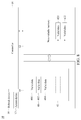
FIG. 1 is a schematic diagram of a hybrid memory system 10, in accordance with some embodiments of the present disclosure. Referring to FIG. 1, the hybrid memory system 10 includes a non-volatile memory 12, a volatile memory 14, a refresh device 16, an access device 17 and a controller 18. In the present embodiment, the hybrid memory system 10 is integrated in a device, and enclosed in a housing. However, the present disclosure is not limited thereto.
The non-volatile memory 12 functions to store data. In an embodiment, the non-volatile memory 12 includes a NAND flash memory. In other embodiments, the non-volatile memory 12 includes a read-only memory (ROM), a programmable read-only memory (PROM), an electrically alterable read-only memory (EAROM), an erasable programmable read-only memory (EPROM), or an electrically erasable programmable read-only memory (EEPROM).
The volatile memory 14 functions to store data. The volatile memory 14, in the present embodiment, includes a dynamic random access memory (DRAM). The volatile memory 14 includes a memory array. The memory array includes a plurality of memory cells 140. The memory cell 140 functions to store data. In addition to the memory cells 140, the memory array further includes a plurality of word lines WL1 to WLn and a plurality of bit lines BL1 to BLm, wherein n and m are positive integers. The word lines WL1 to WLn and the bit lines BL1 to BLm are used to control operation of the associated memory cells 140. The memory cells 140 in a single row and a word line for accessing those memory cells 140 can together be deemed as a memory row. However, the present disclosure is not limited thereto.
The refresh device 16 functions to perform a self-refresh operation on the volatile memory 14. The self-refresh operation refers to the procedure in which the refresh device 16 automatically executes a refresh operation by, for example, using an internal refresh counter. There is no need for the refresh device 16 to obtain refresh request from, for example, a processor external to the hybrid memory system 10 to perform the self-refresh operation. The refresh device 16 and/or other devices in the hybrid memory system 10 can generate, on their own, any information required to perform the self-refresh operation. Additionally, the refresh device 16 refreshes the volatile memory 14 in a fashion in which, for example, a charge is read from the memory cell 140, and the charge is immediately written hack to the memory cell 140. However, the present disclosure is not limited thereto. The refresh operation may further include other detailed operations.
The access device 17, connected to the refresh device 16 and the volatile memory 14, functions to access the volatile memory 14 to obtain the data stored in the volatile memory 14, in particular, the memory cell 140.
The controller 18, connected to the refresh device 16 and the non-volatile memory 12, functions to control the refresh device 16 and the access device 17. In particular, the controller 18 functions to control a movement of a data between the non-volatile memory 12 and the volatile memory 14.
During operation, the controller 18 receives a command to enter a power-saving mode, and, in response to the command, moves data stored in the volatile memory 14 from the volatile memory 14 to the nonvolatile memory 12.
Generally, in a power-saving mode, a refresh device is required to perform a self-refresh operation on a volatile memory to maintain data integrity.
Since the data was moved from the volatile memory 14 to the non-volatile memory 12, there is no data stored in the volatile memory 14. Thus, there is no longer a need for the self-refresh operation to be performed on the volatile memory 14 to maintain data integrity. Accordingly, by disabling the self-refresh function on the volatile memory 14, the controller 18 precludes the volatile memory 14 from having the self-refresh operation performed thereon after the movement of the data and in particular in the power-saving mode.
In the present disclosure, since the volatile memory 14 in the power-saving mode is disabled, power consumption of the volatile memory 14 in the power-saving mode is relatively efficient.
In some existing DRAMs, it is still necessary to perform a self-refresh operation on the DRAMs in a power-saving mode to maintain data integrity. Hence, power consumption the DRAMs is relatively inefficient.
FIG. 2 is a flow chart of a method 20 of operating a hybrid memory system, in accordance with some embodiments of the present disclosure. Referring to FIG. 2, the method 20 includes operations 22 and 24.
The method 20 begins with operation 22, in which data stored in a volatile memory is moved from the volatile memory to a non-volatile memory in response to a command to enter a power-saving mode.
The method 20 proceeds to operation 24, in which the volatile memory is precluded from having a self-refresh operation performed thereon after the movement of the data and in particular in the power-saving mode.
The method 20 is merely an example, and is not intended to limit the present disclosure beyond what is explicitly recited in the claims. Additional operations can be provided before, during, and after the method 20, and some operations described can be replaced, eliminated, or moved around for additional embodiments of the method.
In the present disclosure, power consumption of a hybrid memory system adopting the method 20 is relatively efficient in a power-saving mode.
FIG. 3 is a schematic diagram of the hybrid memory system 10 shown in FIG. 1 in a scenario, in accordance with some embodiments of the present disclosure. Referring to FIG. 3, in the scenario, the volatile memory 14 stores a data including a valid data 140 and an invalid data 142. In the present embodiment, the valid data 140 refers to data which will be used by the controller 18 or an external processor (not shown) electrically connected to the hybrid memory system 10. Conversely, the invalid data 142 refers to data which will not be used. However, the present disclosure is not limited thereto. In other embodiments, there may be another appropriate basis on which to classify a valid data and an invalid data.
During operation, the controller 18 identifies the valid data 140 from the data according to the information provided by the external processor.
FIG. 4 is a schematic diagram illustrating a movement operation from the volatile memory 14 to the non-volatile memory 12 in the scenario of FIG. 3, in accordance with some embodiments of the present disclosure. Referring to FIG. 4, subsequent to the identification, the controller 18 moves the valid data 140 from the volatile memory 14 to the non-volatile memory 12 in response to the command.
Since only the valid data 140 is moved (i.e., the invalid data 142 is not moved), power consumption of the volatile memory 14 is relatively efficient.
FIG. 5 is a schematic diagram illustrating a disabling operation in the scenario of FIG. 3, in accordance with some embodiments of the present disclosure. Referring to FIG. 5, by disabling the volatile memory 14, the controller 18 precludes the volatile memory 14 from having the self-refresh operation performed thereon after the movement of the valid data 140 and in particular in the power-saving is mode.
Without the self-refresh operation in the power-saving mode, the invalid data 142 will eventually be lost. However, the invalid data 142 will not be used. Hence, data integrity is not affected.
In the present disclosure, since the volatile memory 14 in the power-saving mode is disabled, power consumption of the volatile memory 14 in the power-saving mode is relatively efficient.
FIG. 6 is a flow chart of another method 30 of operating a hybrid memory system, in accordance with some embodiments of the present disclosure. Referring to FIG. 6, the method 30 includes operations 32, 34 and 36.
The method 30 begins with operation 32, in which a valid data is identified from data stored in a volatile memory.
The method 30 proceeds to operation 34, in which the valid data is moved from the volatile memory to a non-volatile memory in response to a command to enter a power-saving mode.
The method 30 continues with operation 36, in which the volatile memory without the valid data is precluded from having a self-refresh operation performed thereon after the movement of the valid data and in particular in the power-saving mode.
The method 30 is merely an example, and is not intended to limit the present disclosure beyond what is explicitly recited in the claims. Additional operations can be provided before, during, and after the method 30, and some operations described can be replaced, eliminated, or moved around for additional embodiments of the method.
In the present disclosure, power consumption of a hybrid memory system adopting the method 30 is relatively efficient in a power-saving mode.
FIG. 7 is a schematic diagram of the hybrid memory system 10 shown in FIG. 1 in another scenario, in accordance with some embodiments of the present disclosure. Referring to FIG. 7, the volatile memory 14 includes a first refresh area 40 and a second refresh area 42.
The first refresh area 40 stores first valid data 400, 402 and 404. Such quantity of the valid data only serves as an example. The first refresh area 40, in some embodiments, includes a plurality of memory rows. However, the present disclosure is not limited thereto. In some embodiments, the first refresh area 40 includes a single memory row. Moreover, in some embodiments, the memory rows of the first refresh area 40 belong to a single bank. However, the present disclosure is not limited thereto. The memory rows may belong to different banks. That is, the first refresh area 40 may include a single bank, a plurality of banks, a single memory row, or a plurality of memory rows. The present disclosure is not limited to any specific type as previously mentioned.
The second refresh area 42 stores second valid data 420 and 422. That is, a second quantity of the second valid data is less than the first quantity of the first valid data. Such quantity of valid data only serves as an example. The second refresh area 42 includes a plurality of memory rows. However, the present disclosure is not limited thereto. In some embodiments, the second refresh area 42 includes a single memory row. Moreover, in some embodiments, the memory rows of the second refresh area 42 belong to a single bank. However, the present disclosure is not limited thereto. The memory rows may belong to different banks. That is, the second refresh area 42 may include a single bank, a plurality of banks, a single memory row, or a plurality of memory rows. The present disclosure is not limited to any specific type as previously mentioned.
During operation, the controller 18 determines that the second quantity is less than the first quantity according to a storing data record which is maintained by the information from the external processor.
FIG. 8 is a schematic diagram illustrating a movement operation from the volatile memory 14 to the non-volatile memory 12 in the scenario of FIG. 7, in accordance with some embodiments of the present disclosure. Referring to FIG. 8, the controller 18 moves only the second valid data 420 and 422 (i.e., moves the lesser second quantity) to the non-volatile memory 12 in response to the command.
FIG. 9 is a schematic diagram illustrating a disabling operation in the scenario of FIG. 7, in accordance with some embodiments of the present disclosure. Referring to FIG. 9, the controller 18 disables the second refresh area 42 whose valid data 420 and 422 was moved to the non-volatile memory 12.
FIG. 10 is a schematic diagram illustrating a partial-self-refresh operation in the scenario of FIG. 7, in accordance with some embodiments of the present disclosure. Referring to FIG. 10, by disabling the second refresh area 42, the controller 18 precludes the second refresh area 42 from having a partial-self-refresh operation performed thereon after the movement of the second valid data 420 and 422. However, the controller 14 allows the first refresh area 40 to have the partial-self-refresh operation performed thereon to maintain data integrity of the first valid data 400, 402 and 404.
In the present disclosure, in a power-saving mode, instead of a self-refresh operation, a partial-self-refresh operation is performed. As a result, power consumption of the volatile memory 14 in the power-saving mode is relatively efficient.
In some existing DRAMs, in a power-saving mode, a self-refresh operation is performed, such that all of refresh areas of the DRAMs are required to be refreshed. As a result, power consumption of the DRAMs is relatively inefficient.
FIG. 11 is a flow chart of yet another method 50 of operating a hybrid memory system, in accordance with some embodiments of the present disclosure. Referring to FIG. 11, the method 50 includes operations 52, 54, 56 and 58.
The method 50 begins with operation 52, in which a valid data is identified from data stored in each of a first refresh area and a second refresh area.
The method 50 proceeds to operation 54, in which it is determined that the first refresh area stores a greater quantity of valid data than the second refresh area.
The method 50 continues with operation 56, in which the valid data is moved from the second refresh area to a non-volatile memory in response to a command to enter a power-saving mode.
The method 50 continues with operation 58, in which the second refresh area is precluded from having a partial-self-refresh operation performed thereon after the movement of the valid data.
The method 50 is merely an example, and is not intended to limit the present disclosure beyond what is explicitly recited in the claims. Additional operations can be provided before, during, and after the method 50, and some operations described can be replaced, eliminated, or moved around for additional embodiments of the method.
In the present disclosure, power consumption of a hybrid memory system adopting the method 50 is relatively efficient in a power-saving mode.
FIG. 12 is a schematic diagram illustrating another movement operation from the non-volatile memory 12 to the volatile memory 14, in accordance with some embodiments of the present disclosure. Operations described and illustrated with reference to FIGS. 12 to 14 are able to be subsequent to each of a first embodiment shown in FIG. 1, a second embodiment shown in FIGS. 3 to 5, and a third embodiment shown in FIGS. 7 to 10, when appropriate.
Referring to FIG. 12, the volatile memory 14 includes a first memory row 60, a second memory row 62 and a third memory row 64.
The first memory row 60 includes memory spaces 600, 602 and 604.
The second memory row 62 includes memory spaces 620, 622 and 624.
The third memory row 64 includes memory spaces 640, 642 and 644.
The non-volatile memory 12 stores first valid data 630 and 632 from the first memory row 60, second valid data 634 and 636 from the second memory row 62 and third valid data 638 from the third memory row 64 in response to the command.
During operation, the controller 18, in response to a command to exit from the power-saving mode, moves the valid data 630, 632, 634, 636 and 638 back to the first memory row 60 until the first memory row 60 has no sufficient memory spaces to store more valid data. Next, the controller 18 moves the remaining valid data to the second memory row 62.
FIG. 13 is a schematic diagram illustrating another refresh operation, in accordance with some embodiments of the present disclosure. Referring to FIG. 13, in further detail, the controller 18 moves the first valid data 630 and 632 and the second valid data 634 from the non-volatile memory 12 back to the memory spaces 600, 602, and 604, respectively, of the first memory row 60, in response to a command to exit from the power-saving mode.
Moreover, the controller 18 moves the second valid data 636 and the third valid data 638 from the non-volatile memory 12 back to the memory spaces 620 and 622, respectively, of the second memory row 62, in response to a command to exit from the power-saving mode.
The third memory row 64, which provided the third valid data 638 in response to a command to enter a power-saving mode, does not store any valid data from the non-volatile memory 12 in response to a command to exit from the power-saving mode. In short, the valid data 630, 632, 634, 636 and 638 are centralized to the first memory row 60 and the second memory row 62.
After the movement of the valid data 630, 632, 634, 636 and 638 back to the volatile memory 14, the controller 16 allows the first memory row 60 and the second memory row 62 to have a partial-self-refresh operation performed thereon to maintain data integrity of the valid data 630, 632, 634, 636 and 638. Moreover, the controller 16 precludes the third memory row 64 from having the partial-self-refresh operation performed thereon. As a result, as discussed in the embodiment of FIG. 10, power consumption of the volatile memory 14 in the power-saving mode is relatively efficient.
FIG. 14 is a schematic diagram illustrating an access operation of the hybrid memory system 10 shown in FIG. 1, in accordance with some embodiments of the present disclosure. Referring to FIG. 14, after the movement of the valid data 630, 632, 634, 636 and 638 back to the volatile memory 14, the controller 18 allows the first memory row 60 and the second memory row 62 to be accessed and prohibits the third memory row 64 from being accessed for the valid data 638.
Generally, to access a data from a memory row, it is necessary to perform many preparation operations, such as a pre-charge operation, an active operation, and/or other operations.
In the present embodiment, the third valid data 638, which was provided by the third memory row 64, is stored with the second valid data 636 in the second memory row 62. There is no need to perform the preparation operation to access the third memory row 64 when it is necessary to access the third valid data 638. In further detail, the preparation operation, which would otherwise be performed for three memory rows 60, 62 and 64, are performed for only two memory rows 60 and 62. As a result, an access of the volatile memory 14 is relatively efficient.
FIG. 15 is a flow chart of still another method 70 of operating a hybrid memory system, in accordance with some embodiments of the present disclosure. Referring to FIG. 15, the method 70 includes operations 700, 702, 704, 706, 708, 710 and 712.
The method 70 begins with operation 700, in which a first valid data from a first memory row is stored in a non-volatile memory in response to a command to enter a power-saving mode.
The method 70 proceeds to operation 702, in which a second valid data from a second memory row is stored in the non-volatile memory in response to the command.
The method 70 continues with operation 704, in which the first valid data and the second valid data are moved from the non-volatile memory back to the first memory row in response to a command to exit from the power-saving mode.
The method 70 proceeds to operation 706, in which the first memory row is allowed to have a partial-self-refresh operation performed thereon after the movement of the first valid data and the second valid data back to the first memory row.
The method 70 continues with operation 708, in which the second memory row is precluded from having the partial-self-refresh operation performed thereon after the movement of the valid data.
The method 70 proceeds to operation 710, in which the first memory row is allowed to be accessed.
The method 70 continues with operation 712, in which the second memory row is prohibited from being accessed for the second valid data.
The method 70 is merely an example, and is not intended to limit the present disclosure beyond what is explicitly recited in the claims. Additional operations can be provided before, during, and after the method 70, and some operations described can be replaced, eliminated, or moved around for additional embodiments of the method.
In the present disclosure, power consumption of a hybrid memory system adopting the method 70 is relatively efficient in a power-saving mode.
In the present disclosure, since the volatile memory 14 in the power-saving mode is disabled, power consumption of the volatile memory 14 in the power-saving mode is relatively efficient.
One aspect of the present disclosure provides a hybrid memory system. The hybrid memory system includes a non-volatile memory, a volatile memory and a controller. The volatile memory is configured to store data. The controller is configured to move the data from the volatile memory to the non-volatile memory in response to a command to enter a power-saving mode. The controller is configured to preclude the volatile memory from having a self-refresh operation performed thereon after the movement of the data.
Another aspect of the present disclosure provides a hybrid memory system. The hybrid memory system comprises a volatile memory and a non-volatile memory. The volatile memory includes a first memory row and a second memory row. The non-volatile memory is configured to store a first valid data from the first memory row and a second valid data from the second memory row, in response to a command to enter a power-saving mode. The controller is configured to, in response to a command to exit from the power-saving mode, move both the first valid data and the second valid data to the first memory row. The controller is configured to, in response to the command, preclude the second memory row from being accessed for the second valid data.
Another aspect of the present disclosure provides a method. The method comprises storing data in a volatile memory; moving the data from the volatile memory to a non-volatile memory in response to a command to enter a power-saving mode; and precluding the volatile memory from having a self-refresh operation performed thereon after the movement of the data.
Although the present disclosure and its advantages have been described in detail, it should be understood that various changes, substitutions and alterations can be made herein without departing from the spirit and scope of the disclosure as defined by the appended claims. For example, many of the processes discussed above can be implemented in different methodologies and replaced by other processes, or a combination thereof.
Moreover, the scope of the present application is not intended to be limited to the particular embodiments of the process, machine, manufacture, and composition of matter, means, methods and steps described in the specification. As one of ordinary skill in the art will readily appreciate from the present disclosure, processes, machines, manufacture, compositions of matter, means, methods, or steps, presently existing or later to be developed, that perform substantially the same function or achieve substantially the same result as the corresponding embodiments described herein may be utilized according to the present disclosure. Accordingly, the appended claims are intended to include within their scope such processes, machines, manufacture, compositions of matter, means, methods, or steps.

Claims (11)

What is claimed is:
1. A hybrid memory system, comprising:
a non-volatile memory;
a volatile memory configured to store data; and
a controller configured to move at least a portion of the data from the volatile memory to the non-volatile memory in response to a command to enter a power-saving mode, and to preclude a location of the volatile memory from having a self-refresh operation, wherein the location is a location from where the portion of the data was moved,
wherein the volatile memory includes:
a first refresh area configured to store a first quantity of a first valid data; and
a second refresh area configured to store a second quantity, less than the first quantity, of a second valid data, wherein the portion of the data is the second valid data, and the first valid data is other portions of the data,
wherein the controller is configured to move only the second valid data to the non-volatile memory in response to the command, and to preclude the second refresh area from having a partial-self-refresh operation performed thereon after the movement of the second valid data,
wherein the location is the second refresh area, and
wherein the controller is configured to allow the first refresh area to have the partial-self-refresh operation performed thereon after the movement of the second valid data.
2. The hybrid memory system of claim 1, wherein the controller is further configured to identify the first valid data and the second valid data from the data.
3. The hybrid memory system of claim 1, wherein the volatile memory includes a memory row,
wherein the controller is further configured to move the first valid data and the second valid data from the non-volatile memory back to the volatile memory in response to a command to exit from the power-saving mode,
wherein the memory row stores no valid data after the movement of the first valid data and the second valid data back to the volatile memory, and
wherein the controller is configured to preclude the memory row from having the partial-self-refresh operation performed thereon after the movement of the first valid data and the second valid data back to the volatile memory.
4. The hybrid memory system of claim 1, wherein the volatile memory includes a first memory row and a second memory row,
wherein the non-volatile memory is configured to store the first valid data from the first memory row and the second valid data from the second memory row in response to the command,
wherein the controller is further configured to move the first valid data and the second valid data from the non-volatile memory back to the first memory row in response to a command to exit from the power-saving mode, and
wherein after the movement of the first valid data and the second valid data back to the first memory row, the controller is configured to allow the first memory row to have a partial-self-refresh operation performed thereon and to continue to preclude the second memory row from having the partial-self-refresh operation performed thereon.
5. The hybrid memory system of claim 4, wherein after the movement of the first valid data and the second valid data back to the first memory row, the controller is further configured to allow the first memory row to be accessed.
6. A hybrid memory system, comprising:
a volatile memory including:
a first memory row; and
a second memory row;
a non-volatile memory configured to store a first valid data from the first memory row and a second valid data from the second memory row, in response to a command to enter a power-saving mode; and
a controller configured to, in response to a command to exit from the power-saving mode, move both the first valid data and the second valid data to the first memory row, and preclude the second memory row from being accessed for the second valid data.
7. The hybrid memory system of claim 6, wherein the controller is further configured to preclude the second memory row from having the partial-self-refresh operation performed thereon.
8. A method, comprising:
storing data in a volatile memory, the data comprising a first portion and a second portion;
storing a first quantity of a first valid data by a first refresh area, wherein the first valid data is the first portion of the data;
storing a second quantity, less than the first quantity, of a second valid data by a second refresh area, wherein the second portion of the data is the second valid data;
moving only the second valid data from the volatile memory to a non-volatile memory in response to a command to enter a power-saving mode;
precluding the second refresh area from having a partial-self-refresh operation performed thereon after the movement of the second valid data, and the second refresh area is a location from where the second valid data was moved; and
allowing the first refresh area to have the partial-self-refresh operation performed thereon after the movement of the second valid data.
9. The method of claim 8,
wherein the first valid data and the second valid data are stored from a memory row of the volatile memory in the non-volatile memory in response to the command; and
the method further comprising:
moving the first valid data and the second valid data from the non-volatile memory back to the volatile memory in response to a command to exit from the power-saving mode; and
precluding the memory row from having the partial-self-refresh operation performed thereon after the movement of the first valid data and the second valid data back to the volatile memory, wherein the memory row stores no valid data after the movement of the first valid data and the second valid data back to the volatile memory.
10. The method of claim 9, further comprising:
precluding the memory row from being accessed for the first valid data and the second valid data after the movement of the first valid data and the second valid data back to the volatile memory.
11. The method of claim 8,
wherein the first valid data is stored from a first memory row of the volatile memory in the non-volatile memory in response to the command;
wherein the second valid data is stored from a second memory row of the volatile memory in the non-volatile memory in response to the command; and
the method further comprising:
moving the first valid data and the second valid data from the non-volatile memory back to the first memory row in response to a command to exit from the power-saving mode; and
allowing the first memory row to have a partial-self-refresh operation performed thereon and continuing to preclude the second memory row from having the partial-self-refresh operation performed thereon after the movement of the first valid data and the second valid data back to the first memory row.
US15/900,013 2017-12-22 2018-02-20 Hybrid memory system and method of operating the same Active US10437499B2 (en)

Priority Applications (3)

Application Number Priority Date Filing Date Title
US15/900,013 US10437499B2 (en) 2017-12-22 2018-02-20 Hybrid memory system and method of operating the same
TW107123353A TWI687929B (en) 2017-12-22 2018-07-05 Hybrid memory system and method of operating the same
CN201810890246.9A CN109960465B (en) 2017-12-22 2018-08-07 Hybrid memory system and method of operating the same

Applications Claiming Priority (2)

Application Number Priority Date Filing Date Title
US201762609641P 2017-12-22 2017-12-22
US15/900,013 US10437499B2 (en) 2017-12-22 2018-02-20 Hybrid memory system and method of operating the same

Publications (2)

Publication Number Publication Date
US20190196733A1 US20190196733A1 (en) 2019-06-27
US10437499B2 true US10437499B2 (en) 2019-10-08

Family

ID=66950298

Family Applications (1)

Application Number Title Priority Date Filing Date
US15/900,013 Active US10437499B2 (en) 2017-12-22 2018-02-20 Hybrid memory system and method of operating the same

Country Status (3)

Country Link
US (1) US10437499B2 (en)
CN (1) CN109960465B (en)
TW (1) TWI687929B (en)

Families Citing this family (3)

* Cited by examiner, † Cited by third party
Publication number Priority date Publication date Assignee Title
JP2020030875A (en) * 2018-08-23 2020-02-27 キオクシア株式会社 Memory system
KR20210039075A (en) * 2019-10-01 2021-04-09 삼성전자주식회사 Method of controlling initialization of nonvolatile memory device and memory system including nonvolatile memory device
US11449346B2 (en) * 2019-12-18 2022-09-20 Advanced Micro Devices, Inc. System and method for providing system level sleep state power savings

Citations (4)

* Cited by examiner, † Cited by third party
Publication number Priority date Publication date Assignee Title
US20090027989A1 (en) * 2007-07-26 2009-01-29 Qualcomm Incorporated System and Method to Reduce Dynamic Ram Power Consumption via the use of Valid Data Indicators
US20100274960A1 (en) * 2009-04-24 2010-10-28 Lee Kun-Bin Memory control method of memory device and memory control system thereof
US20140192583A1 (en) * 2005-06-24 2014-07-10 Suresh Natarajan Rajan Configurable memory circuit system and method
US20140304475A1 (en) * 2011-12-20 2014-10-09 Raj K Ramanujan Dynamic partial power down of memory-side cache in a 2-level memory hierarchy

Family Cites Families (3)

* Cited by examiner, † Cited by third party
Publication number Priority date Publication date Assignee Title
US7554855B2 (en) * 2006-12-20 2009-06-30 Mosaid Technologies Incorporated Hybrid solid-state memory system having volatile and non-volatile memory
CN106406492B (en) * 2015-07-30 2019-10-25 华为技术有限公司 Mixing storage equipment, computer, control equipment and the method for reducing power consumption
US10268405B2 (en) * 2016-03-17 2019-04-23 Mediatek, Inc. Dynamic rank switching for low power volatile memory

Patent Citations (4)

* Cited by examiner, † Cited by third party
Publication number Priority date Publication date Assignee Title
US20140192583A1 (en) * 2005-06-24 2014-07-10 Suresh Natarajan Rajan Configurable memory circuit system and method
US20090027989A1 (en) * 2007-07-26 2009-01-29 Qualcomm Incorporated System and Method to Reduce Dynamic Ram Power Consumption via the use of Valid Data Indicators
US20100274960A1 (en) * 2009-04-24 2010-10-28 Lee Kun-Bin Memory control method of memory device and memory control system thereof
US20140304475A1 (en) * 2011-12-20 2014-10-09 Raj K Ramanujan Dynamic partial power down of memory-side cache in a 2-level memory hierarchy

Also Published As

Publication number Publication date
CN109960465B (en) 2022-07-26
US20190196733A1 (en) 2019-06-27
CN109960465A (en) 2019-07-02
TW201928974A (en) 2019-07-16
TWI687929B (en) 2020-03-11

Similar Documents

Publication Publication Date Title
US10437499B2 (en) Hybrid memory system and method of operating the same
US9653139B1 (en) Simultaneous plural wordline within a bank refreshing control device and memory device including the same
US20200251158A1 (en) Apparatuses and methods for managing row access counts
EP1749300B1 (en) Method and system for providing directed bank refresh for volatile memories
US10236035B1 (en) DRAM memory device adjustable refresh rate method to alleviate effects of row hammer events
US7236416B2 (en) Method and system for controlling refresh in volatile memories
CN105989870B (en) Memory device and memory system including the same
KR20150033949A (en) Memory and memory system including the same
CN108932959B (en) Memory device performing care operation for interfered row and operation method thereof
US10304516B1 (en) DRAM for storing data and method of operating the same
US7038943B2 (en) Memory array having 2T memory cells
JP6746522B2 (en) Semiconductor memory device
US10276228B1 (en) DRAM and method of operating the same
US10380024B2 (en) DRAM and method of operating the same in an hierarchical memory system
US10127967B1 (en) DRAM and method for operating the same
US20190066760A1 (en) Dram and method for operating the same
US10262719B1 (en) DRAM and refresh method thereof
US10497426B1 (en) Target row generator, DRAM, and method for determining a target row
US10930336B1 (en) Memory device and row-hammer refresh method thereof
US9236112B1 (en) Apparatuses and methods for reducing cycle times in successive memory accesses
US10698609B2 (en) Memory system and operating method of a memory system
KR20110131634A (en) Bank group refresh control device
US20190066765A1 (en) Dram and method for operating the same
TWI652674B (en) Dynamic random access memory
KR20120098055A (en) Memory device and method for refresh controlling the same

Legal Events

Date Code Title Description
FEPP Fee payment procedure

Free format text: ENTITY STATUS SET TO UNDISCOUNTED (ORIGINAL EVENT CODE: BIG.); ENTITY STATUS OF PATENT OWNER: LARGE ENTITY

AS Assignment

Owner name: NANYA TECHNOLOGY CORPORATION, TAIWAN

Free format text: ASSIGNMENT OF ASSIGNORS INTEREST;ASSIGNORS:LEE, CHUNG-HSUN;LIU, HSIEN-WEN;REEL/FRAME:045017/0303

Effective date: 20171108

STPP Information on status: patent application and granting procedure in general

Free format text: NOTICE OF ALLOWANCE MAILED -- APPLICATION RECEIVED IN OFFICE OF PUBLICATIONS

STPP Information on status: patent application and granting procedure in general

Free format text: PUBLICATIONS -- ISSUE FEE PAYMENT RECEIVED

STPP Information on status: patent application and granting procedure in general

Free format text: PUBLICATIONS -- ISSUE FEE PAYMENT VERIFIED

STCF Information on status: patent grant

Free format text: PATENTED CASE

MAFP Maintenance fee payment

Free format text: PAYMENT OF MAINTENANCE FEE, 4TH YEAR, LARGE ENTITY (ORIGINAL EVENT CODE: M1551); ENTITY STATUS OF PATENT OWNER: LARGE ENTITY

Year of fee payment: 4