US10436494B2 - Refrigerator - Google Patents
Refrigerator Download PDFInfo
- Publication number
- US10436494B2 US10436494B2 US15/549,926 US201615549926A US10436494B2 US 10436494 B2 US10436494 B2 US 10436494B2 US 201615549926 A US201615549926 A US 201615549926A US 10436494 B2 US10436494 B2 US 10436494B2
- Authority
- US
- United States
- Prior art keywords
- deep
- case
- freezing
- chamber
- evaporator
- Prior art date
- Legal status (The legal status is an assumption and is not a legal conclusion. Google has not performed a legal analysis and makes no representation as to the accuracy of the status listed.)
- Active
Links
- 238000007710 freezing Methods 0.000 claims abstract description 90
- 238000001816 cooling Methods 0.000 claims abstract description 35
- 239000003507 refrigerant Substances 0.000 claims abstract description 25
- 235000013305 food Nutrition 0.000 claims abstract description 10
- 238000001704 evaporation Methods 0.000 claims description 22
- 230000008020 evaporation Effects 0.000 claims description 22
- 238000004804 winding Methods 0.000 claims description 2
- 230000008014 freezing Effects 0.000 description 35
- 230000004888 barrier function Effects 0.000 description 5
- 230000008901 benefit Effects 0.000 description 4
- 238000010791 quenching Methods 0.000 description 4
- 230000000171 quenching effect Effects 0.000 description 4
- 235000013372 meat Nutrition 0.000 description 3
- 230000005679 Peltier effect Effects 0.000 description 2
- 238000010586 diagram Methods 0.000 description 2
- 230000000694 effects Effects 0.000 description 2
- 238000005057 refrigeration Methods 0.000 description 2
- 241000251468 Actinopterygii Species 0.000 description 1
- 229910052782 aluminium Inorganic materials 0.000 description 1
- XAGFODPZIPBFFR-UHFFFAOYSA-N aluminium Chemical compound [Al] XAGFODPZIPBFFR-UHFFFAOYSA-N 0.000 description 1
- 238000005219 brazing Methods 0.000 description 1
- 230000006378 damage Effects 0.000 description 1
- 235000005911 diet Nutrition 0.000 description 1
- 230000000378 dietary effect Effects 0.000 description 1
- 239000011810 insulating material Substances 0.000 description 1
- 239000007788 liquid Substances 0.000 description 1
- 239000007769 metal material Substances 0.000 description 1
- 238000010257 thawing Methods 0.000 description 1
- 238000003466 welding Methods 0.000 description 1
Images


Classifications
-
- F—MECHANICAL ENGINEERING; LIGHTING; HEATING; WEAPONS; BLASTING
- F25—REFRIGERATION OR COOLING; COMBINED HEATING AND REFRIGERATION SYSTEMS; HEAT PUMP SYSTEMS; MANUFACTURE OR STORAGE OF ICE; LIQUEFACTION SOLIDIFICATION OF GASES
- F25D—REFRIGERATORS; COLD ROOMS; ICE-BOXES; COOLING OR FREEZING APPARATUS NOT OTHERWISE PROVIDED FOR
- F25D11/00—Self-contained movable devices, e.g. domestic refrigerators
- F25D11/02—Self-contained movable devices, e.g. domestic refrigerators with cooling compartments at different temperatures
- F25D11/022—Self-contained movable devices, e.g. domestic refrigerators with cooling compartments at different temperatures with two or more evaporators
-
- F—MECHANICAL ENGINEERING; LIGHTING; HEATING; WEAPONS; BLASTING
- F25—REFRIGERATION OR COOLING; COMBINED HEATING AND REFRIGERATION SYSTEMS; HEAT PUMP SYSTEMS; MANUFACTURE OR STORAGE OF ICE; LIQUEFACTION SOLIDIFICATION OF GASES
- F25B—REFRIGERATION MACHINES, PLANTS OR SYSTEMS; COMBINED HEATING AND REFRIGERATION SYSTEMS; HEAT PUMP SYSTEMS
- F25B21/00—Machines, plants or systems, using electric or magnetic effects
- F25B21/02—Machines, plants or systems, using electric or magnetic effects using Peltier effect; using Nernst-Ettinghausen effect
-
- F—MECHANICAL ENGINEERING; LIGHTING; HEATING; WEAPONS; BLASTING
- F25—REFRIGERATION OR COOLING; COMBINED HEATING AND REFRIGERATION SYSTEMS; HEAT PUMP SYSTEMS; MANUFACTURE OR STORAGE OF ICE; LIQUEFACTION SOLIDIFICATION OF GASES
- F25B—REFRIGERATION MACHINES, PLANTS OR SYSTEMS; COMBINED HEATING AND REFRIGERATION SYSTEMS; HEAT PUMP SYSTEMS
- F25B5/00—Compression machines, plants or systems, with several evaporator circuits, e.g. for varying refrigerating capacity
- F25B5/02—Compression machines, plants or systems, with several evaporator circuits, e.g. for varying refrigerating capacity arranged in parallel
-
- F—MECHANICAL ENGINEERING; LIGHTING; HEATING; WEAPONS; BLASTING
- F25—REFRIGERATION OR COOLING; COMBINED HEATING AND REFRIGERATION SYSTEMS; HEAT PUMP SYSTEMS; MANUFACTURE OR STORAGE OF ICE; LIQUEFACTION SOLIDIFICATION OF GASES
- F25D—REFRIGERATORS; COLD ROOMS; ICE-BOXES; COOLING OR FREEZING APPARATUS NOT OTHERWISE PROVIDED FOR
- F25D11/00—Self-contained movable devices, e.g. domestic refrigerators
- F25D11/02—Self-contained movable devices, e.g. domestic refrigerators with cooling compartments at different temperatures
- F25D11/025—Self-contained movable devices, e.g. domestic refrigerators with cooling compartments at different temperatures using primary and secondary refrigeration systems
-
- F—MECHANICAL ENGINEERING; LIGHTING; HEATING; WEAPONS; BLASTING
- F25—REFRIGERATION OR COOLING; COMBINED HEATING AND REFRIGERATION SYSTEMS; HEAT PUMP SYSTEMS; MANUFACTURE OR STORAGE OF ICE; LIQUEFACTION SOLIDIFICATION OF GASES
- F25D—REFRIGERATORS; COLD ROOMS; ICE-BOXES; COOLING OR FREEZING APPARATUS NOT OTHERWISE PROVIDED FOR
- F25D11/00—Self-contained movable devices, e.g. domestic refrigerators
- F25D11/04—Self-contained movable devices, e.g. domestic refrigerators specially adapted for storing deep-frozen articles
-
- F—MECHANICAL ENGINEERING; LIGHTING; HEATING; WEAPONS; BLASTING
- F25—REFRIGERATION OR COOLING; COMBINED HEATING AND REFRIGERATION SYSTEMS; HEAT PUMP SYSTEMS; MANUFACTURE OR STORAGE OF ICE; LIQUEFACTION SOLIDIFICATION OF GASES
- F25D—REFRIGERATORS; COLD ROOMS; ICE-BOXES; COOLING OR FREEZING APPARATUS NOT OTHERWISE PROVIDED FOR
- F25D19/00—Arrangement or mounting of refrigeration units with respect to devices or objects to be refrigerated, e.g. infrared detectors
- F25D19/006—Thermal coupling structure or interface
-
- F—MECHANICAL ENGINEERING; LIGHTING; HEATING; WEAPONS; BLASTING
- F25—REFRIGERATION OR COOLING; COMBINED HEATING AND REFRIGERATION SYSTEMS; HEAT PUMP SYSTEMS; MANUFACTURE OR STORAGE OF ICE; LIQUEFACTION SOLIDIFICATION OF GASES
- F25D—REFRIGERATORS; COLD ROOMS; ICE-BOXES; COOLING OR FREEZING APPARATUS NOT OTHERWISE PROVIDED FOR
- F25D25/00—Charging, supporting, and discharging the articles to be cooled
- F25D25/02—Charging, supporting, and discharging the articles to be cooled by shelves
- F25D25/024—Slidable shelves
- F25D25/025—Drawers
-
- F—MECHANICAL ENGINEERING; LIGHTING; HEATING; WEAPONS; BLASTING
- F25—REFRIGERATION OR COOLING; COMBINED HEATING AND REFRIGERATION SYSTEMS; HEAT PUMP SYSTEMS; MANUFACTURE OR STORAGE OF ICE; LIQUEFACTION SOLIDIFICATION OF GASES
- F25B—REFRIGERATION MACHINES, PLANTS OR SYSTEMS; COMBINED HEATING AND REFRIGERATION SYSTEMS; HEAT PUMP SYSTEMS
- F25B2321/00—Details of machines, plants or systems, using electric or magnetic effects
- F25B2321/02—Details of machines, plants or systems, using electric or magnetic effects using Peltier effects; using Nernst-Ettinghausen effects
- F25B2321/025—Removal of heat
- F25B2321/0252—Removal of heat by liquids or two-phase fluids
-
- F—MECHANICAL ENGINEERING; LIGHTING; HEATING; WEAPONS; BLASTING
- F25—REFRIGERATION OR COOLING; COMBINED HEATING AND REFRIGERATION SYSTEMS; HEAT PUMP SYSTEMS; MANUFACTURE OR STORAGE OF ICE; LIQUEFACTION SOLIDIFICATION OF GASES
- F25D—REFRIGERATORS; COLD ROOMS; ICE-BOXES; COOLING OR FREEZING APPARATUS NOT OTHERWISE PROVIDED FOR
- F25D2400/00—General features of, or devices for refrigerators, cold rooms, ice-boxes, or for cooling or freezing apparatus not covered by any other subclass
- F25D2400/28—Quick cooling
Definitions
- the present invention relates to a refrigerator.
- a refrigerator is a household appliance that can store food at low temperature in a storage space of inner portion thereof that is shielded by a door.
- the refrigerator is configured to be capable of storing stored food in an optimal state by cooling the inner portion of the storage space using cooled air generated through heat exchange with the refrigerant circulating in the refrigeration cycle.
- refrigerators have become increasingly larger and multifunctional in accordance with trend of changes in dietary life and high quality of products, and refrigerators having various structures and convenience devices considering convenience of users have been released.
- the meat or fish is frozen, if a freezing point temperature range at which ice in the cell thereof is formed is passed in a short time, the destruction of the cell thereof is minimized and thus there are advantages that the meat quality is kept fresh even after thawing of the meat and delicious food can be cooked.
- the temperature of a quenching chamber can be made lower than the temperature of the freezing chamber by an exothermic surface of a thermoelectric device being attached to a freezing chamber evaporator mounted on a rear side of the freezing chamber and the endothermic surface of the thermoelectric device being installed to face the quenching chamber.
- a thermoelectric device being attached to a freezing chamber evaporator mounted on a rear side of the freezing chamber and the endothermic surface of the thermoelectric device being installed to face the quenching chamber.
- the present invention has been made in order to solve the problems or the related art and an objective of the present invention is to provide a refrigerator which can rapidly cool the quenching chamber temperature to minus 50 degrees Celsius.
- a refrigerator including: a cabinet in which a storage space is formed; a main evaporator which is installed at a side of an inner portion of the storage space to cool the storage space; a case which is installed on the other side of the inner portion of the storage space and defining a deep freezing storage chamber; a drawer which is accommodated in the case so as to be retractable and withdrawable and in which food is stored; and a rapid cooling module which is provided on a rear side of the inner portion of the case for rapidly cooling the deep-freezing storage chamber, in which the rapid cooling module may includes a auxiliary evaporator in which a low-temperature and low-pressure two-phase refrigerant flows; and a thermoelectric device of which an exothermic surface is attached to a surface of the auxiliary evaporator and of which an endothermic surface is installed to face the drawer, thereby cooling the deep-freezing storage chamber.
- the temperature of refrigerant passing through a deep-freezing chamber dedicated evaporator is about minus 35 degrees Celsius and the temperature of the endothermic surface of the thermoelectric device is about minus 30 degrees Celsius.
- the temperature difference between the exothermic surface and the endothermic surface of the thermoelectric device becomes about 25 degrees and the endothermic surface temperature of the thermoelectric device becomes about minus 55 degrees Celsius.
- the temperature of the cooled air of the deep-freezing chamber can be cooled down to about minus 50 degrees Celsius.
- FIG. 1 is a perspective view of a refrigerator having a rapid cooling module according to an embodiment of the present invention
- FIG. 2 is an external perspective view of a deep-freezing storage chamber system according to an embodiment of the present invention
- FIG. 3 is an exploded perspective view of the deep-freezing storage chamber system
- FIG. 4 is an exploded perspective view illustrating a structure of a auxiliary evaporator constituting the rapid cooling module according to an embodiment of the present invention.
- FIG. 5 is a system diagram schematically illustrating a refrigerant circulation system of the refrigerator including the deep-freezing storage chamber system according to an embodiment of the present invention.
- a refrigerator according to an embodiment of the present invention will be described in detail with reference to the drawings.
- a bottom freezer-type refrigerator in which a freezing chamber is provided below a refrigerating chamber is described as an example of a refrigerator according to an embodiment of the present invention, the present invention is not limited thereto and can be also applied to all types of refrigerators.
- FIG. 1 is a perspective view of a refrigerator having a rapid cooling module according to an embodiment of the present invention.
- a refrigerator 1 provided with a rapid cooling module includes a main body 10 which has a storage space therein, a door 20 which selectively opens and closes the storage space, and a deep-freezing storage chamber which is provided independently inside a storage space.
- the inner space of the main body 10 is divided into a refrigerating chamber 12 and a freezing chamber 13 by a barrier 103 .
- the freezing chamber 12 and the freezing chamber 13 are disposed in the lateral direction or in the vertical direction according to the extending direction of the barrier 103 .
- the refrigerating chamber 12 is formed on an upper side or a lower side of the freezing chamber 13 , and in the present embodiment, the refrigerating chamber 12 is disposed the upper side of the freezing chamber 13 .
- the refrigerating chamber 12 and the freezing chamber 13 may be disposed side by side in the lateral direction.
- the deep-freezing storage chamber may be provided at one side edge of the freezing chamber 13 and the deep-freezing storage chamber includes a drawer assembly 30 which stores food and a rapid cooling module 40 (see FIG. 3 ) which rapidly freezes the drawer assembly 30 .
- the rapid cooling module 40 is disposed at a rear end of the drawer assembly 30 , which will be described in more detail below with reference to the drawings.
- the refrigerating chamber 12 is selectively opened and closed by a refrigerating chamber door 21 and can be opened and closed by a single door or a pair of doors as illustrated in the drawings.
- the refrigerating chamber door 21 may be rotatably coupled to the main body 10 .
- the freezing chamber 13 is selectively opened and closed by the freezing chamber door 22 , and in a case of the bottom freezer type refrigerator, the freezing chamber door 22 can be provided to be retractable and withdrawable as illustrated in drawings, that is, an accommodating portion of the freezing chamber can be provided in a form of a drawer.
- the drawer assembly 30 can be accommodated in the deep-freezing storage chamber so as to be retractable and withdrawable in a front-rear direction.
- FIG. 2 is an external perspective view of a deep-freezing storage chamber system according to an embodiment of the present invention
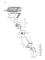
- FIG. 3 is an exploded perspective view of the deep-freezing storage chamber system.
- a deep-freezing storage chamber assembly may include a drawer assembly 30 which defines a deep-freezing storage chamber and a rapid cooling module 40 for cooling an inner portion of the deep-freezing storage chamber to a temperature lower than a temperature of the freezing chamber in a short time.
- the drawer assembly 30 may include a case 31 which is fixedly mounted on one side of an inner portion of the refrigerating chamber 12 or the freezing chamber 13 and defines a deep-freezing storage chamber therein, and a drawer 32 which is coupled to be retractable and withdrawable to the inner portion of the case 31 .
- the case 31 may have a hexahedral shape with at least a front surface opened and a rail guide 311 may be formed on an inner circumferential surface of a side wall thereof to guide the retraction and the withdrawal of the drawer 32 .
- the drawer 32 may include a storage box 322 of which an upper surface is opened so as to store food therein, a box door 321 which is vertically coupled to a front surface of the storage box 322 , and rails 323 which are formed on an outer circumferential surfaces of both side walls of the storage box 322 .
- the rail 323 moves in the front-rear direction along the rail guide 311 to enable sliding movement of the drawer 32 .
- a plurality of cooled air holes 324 are formed on a rear surface of the storage box 322 so that cooled air can be circulated by cooled air supplied from the rapid cooling module 40 being supplied into the storage box 322 and the cooled air in the storage box 322 being returned to the rapid cooling module 40 side.
- a handle portion 325 may be formed on a front surface of the box door 321 .
- the evaporation chamber dividing wall 14 is a wall which divides an inner space of the freezing chamber 13 into a freezing storage chamber and an evaporation chamber in the front-rear direction and a main evaporator 54 which is defined as a freezing chamber evaporator is accommodated in a space formed between a rear wall of the cabinet 10 and the evaporation chamber dividing wall 14 .
- the rapid cooling module 40 is accommodated in the case 31 and divided into the deep-freezing storage chamber and the deep-freezing evaporation chamber by a deep-freezing evaporation chamber cover 33 .
- the inner space of the case 31 corresponding to a front side of the deep-freezing evaporation chamber cover 33 is defined as the deep-freezing storage chamber and the inner space of the case 31 corresponding to a rear side of the deep-freezing evaporation chamber cover 33 can be defined as a deep-freezing evaporation chamber.
- a discharge grill 331 and a suction grill 332 may be formed on a front surface of the deep-freezing evaporation chamber cover 33 , respectively.
- the discharge grill 331 may be positioned above the suction grill 332 and cooled air cooled to a temperature lower than a temperature of the freezing chamber in the deep-freezing evaporation chamber is discharged to the deep-freezing storage chamber.
- the cooled air in the deep-freezing storage chamber is returned to the deep-freezing evaporation chamber through the suction grill 332 .
- the rapid cooling module 40 is accommodated in the deep-freezing evaporation chamber.
- the rapid cooling module 40 may include a auxiliary evaporator 45 which defined as a deep-freezing evaporator, a heat conduction unit 44 which is in close contact with an outer circumference of the auxiliary evaporator 45 , a thermoelectric device 41 which is attached to a front surface of the heat conduction unit 44 , a heat sink 42 which is in close contact with the front surface of the thermoelectric device 41 , and a cooling fan 43 which is placed in front of the heat sink 42 to circulate the cooled air.
- a auxiliary evaporator 45 which defined as a deep-freezing evaporator
- a heat conduction unit 44 which is in close contact with an outer circumference of the auxiliary evaporator 45
- thermoelectric device 41 which is attached to a front surface of the heat conduction unit 44
- a heat sink 42 which is in close contact with the front surface of the thermoelectric device 41
- a cooling fan 43 which is placed
- the thermoelectric device 41 may include a device using a Peltier effect in which an endothermic phenomenon occurs on one surface thereof and an exothermic phenomenon occurs on the other surface thereof due to current supply.
- the Peltier effect is an effect of causing the endothermic phenomenon at one terminal and the exothermic phenomenon at the other terminal depending on the current direction when two kinds of rapid ends are connected and current flows thereto. If the flow direction of the current supplied to the thermoelectric device 41 is switched, the endothermic surface and the exothermic surface are also switched, and there is an advantage that the endothermic amount and the exothermic amount can be adjusted according to the amount of the supplied current.
- the rapid cooling module 40 has a structure in which the endothermic surface of the thermoelectric device 41 is directed toward the drawer assembly 30 of the deep-freezing storage chamber and the exothermic surface directed toward the auxiliary evaporator 45 . Therefore, the rapid cooling module 40 can be used to rapidly cool the food stored in the drawer assembly 30 to a state of a cryogenic temperature state of minus 50 degrees Celsius or less by using the endothermic phenomenon generated in the thermoelectric device 41 .
- FIG. 4 is an exploded perspective view illustrating a structure of the auxiliary evaporator constituting a rapid cooling module according to an embodiment of the present invention.
- the auxiliary evaporator 45 constituting the rapid cooling module 40 may be defined as a deep-freezing chamber evaporator and may be a heat exchanger in which refrigerant flows.
- the auxiliary evaporator 45 may include a front case 451 and a rear case 452 tightly coupled to a rear surface of the front case 451 .
- a refrigerant flow path 455 in the form of a winding meander line or a zigzag line may be formed on any one side or both sides of the rear surface of the front case 451 and the front surface of the rear case 452 .
- the refrigerant flow path 455 performs a refrigerant pipe function of a general heat exchanger and a low-temperature and low-pressure two-phase refrigerant that passes through an expansion valve of a refrigeration cycle flows therethrough.
- a suction port 453 in which refrigerant flows is formed at one side of the rear case 452 and a discharge port 454 from which the refrigerant is discharged is formed at the other side thereof.
- the suction port 453 and the discharge port 454 are formed at positions facing each other, and may be located at one side edge of the rear case 452 or in a diagonally opposite direction to each other.
- the suction port 453 can be located at the upper edge of the rear case 452 and the discharge port 454 can be located at an edge side, which facing the suction port 453 in the diagonal direction, among the lower corners of the rear case 453 .
- the suction port 453 and the discharge port 454 are formed at positions facing each other in the diagonal direction, the suction port 453 is positioned below the rear case 452 , and the discharge port 454 can be positioned on an upper side of the rear case 452 .
- suction port 453 and the discharge port 454 can be located at the upper and lower edges of the left or right edge of the rear case 452 , respectively.
- the front case 451 and the rear case 452 constituting the auxiliary evaporator 45 may be made of a metal material such as aluminum having a high thermal conductivity and may be coupled to each other by brazing welding.
- FIG. 5 is a system diagram schematically illustrating a refrigerant circulation system of a refrigerator including a deep-freezing storage chamber system according to an embodiment of the present invention.
- freezing chamber evaporator 54 that is, a main evaporator 54 for supplying cooled air to the freezing chamber and the refrigerating chamber 12 or to only the freezing chamber 13
- a deep-freezing storage chamber evaporator that is, a auxiliary evaporator 45 for cooling the deep-freezing storage chamber
- Specifically refrigerant circulation system of the refrigerator 1 may include a compressor 50 for compressing the refrigerant into a high-temperature and high-pressure gas state, a condenser 51 for condensing the refrigerant passing through the compressor 50 into a high-temperature and high-pressure liquid state, a main expansion valve 53 which is provided at an outlet side of the condenser 51 , the main evaporator 54 which is connected to an outlet side of the main expansion valve 53 , a auxiliary expansion valve 55 which is branched at any point of a refrigerant pipe P connecting the main expansion valve 53 and the condenser 51 and thus is connected in parallel with the main expansion valve 53 , and auxiliary evaporator 45 which is connected to an outlet side of the auxiliary expansion valve 55 .
- a valve 52 may be mounted at a point where the main expansion valve 53 and the auxiliary expansion valve 55 are branched and may be controlled that the refrigerant passing through the condenser 51 separately flows into the main expansion valve 53 and the auxiliary expansion valve 55 or flows only to either side.
- the cabinet 10 may include an outer cabinet 101 , an inner cabinet 102 , and a heat insulating layer 101 formed between the outer cabinet 101 and the inner cabinet 102 .
- the refrigerating chamber 12 and the freezing chamber 13 are divided and defined by the inner cabinet 102 and the barrier 103 .
- the evaporation chamber dividing wall 14 is installed at a position spaced apart from the rear wall of the inner cabinet 12 to the front side so that a space where the deep-freezing chamber storage system is placed and a space where the main evaporator 54 is placed are divided.
- the cooled air cooled by the main evaporator 54 is supplied to the freezing chamber 13 and then returned to the main evaporator 54 .
- the cooled air cooled by the main evaporator 54 is not supplied to the drawer assembly 30 .
- the case 31 is made of a heat insulating material so that the inner portion of the freezing chamber 13 and the inner portion of the storage box 322 cannot exchange heat with each other.
- thermoelectric device 41 is attached to the surface of the auxiliary evaporator 45 and thus is cooled and the heat sink 42 is attached to the endothermic surface of the thermoelectric device 41 and thus the temperature of the heat sink 42 is cooled to minus 50 degrees Celsius or less.
- the cooled air in the deep-freezing storage chamber which is sucked by the cooling fan 43 is rapidly cooled to minus 50 degrees Celsius while exchanging heat with the heat sink 42 .
- the temperature of the refrigerant passing through the auxiliary evaporator 45 is about minus 35 degrees Celsius and the temperature of the exothermic surface of the thermoelectric device 41 is about minus 30 degrees Celsius.
- the temperature difference between the exothermic surface and the endothermic surface becomes about 25 degrees. Therefore, the temperature of the endothermic surface of the thermoelectric device 41 is about minus 55 degrees Celsius.
- the cooled air temperature of the deep-freezing storage chamber, which is in contact with the endothermic surface of the thermoelectric device 41 and exchanges beat, is about minus 50 degrees Celsius.
Landscapes
- Engineering & Computer Science (AREA)
- Physics & Mathematics (AREA)
- Mechanical Engineering (AREA)
- Thermal Sciences (AREA)
- General Engineering & Computer Science (AREA)
- Chemical & Material Sciences (AREA)
- Combustion & Propulsion (AREA)
- Devices That Are Associated With Refrigeration Equipment (AREA)
Applications Claiming Priority (3)
| Application Number | Priority Date | Filing Date | Title |
|---|---|---|---|
| KR1020150019598A KR102270628B1 (ko) | 2015-02-09 | 2015-02-09 | 냉장고 |
| KR10-2015-0019598 | 2015-02-09 | ||
| PCT/KR2016/001336 WO2016129907A1 (fr) | 2015-02-09 | 2016-02-05 | Réfrigérateur |
Publications (2)
| Publication Number | Publication Date |
|---|---|
| US20180031297A1 US20180031297A1 (en) | 2018-02-01 |
| US10436494B2 true US10436494B2 (en) | 2019-10-08 |
Family
ID=56614472
Family Applications (1)
| Application Number | Title | Priority Date | Filing Date |
|---|---|---|---|
| US15/549,926 Active US10436494B2 (en) | 2015-02-09 | 2016-02-05 | Refrigerator |
Country Status (5)
| Country | Link |
|---|---|
| US (1) | US10436494B2 (fr) |
| EP (2) | EP4354047A2 (fr) |
| KR (1) | KR102270628B1 (fr) |
| CN (1) | CN107110589B (fr) |
| WO (1) | WO2016129907A1 (fr) |
Families Citing this family (17)
| Publication number | Priority date | Publication date | Assignee | Title |
|---|---|---|---|---|
| KR101821290B1 (ko) | 2016-09-02 | 2018-01-23 | 엘지전자 주식회사 | 냉장고 |
| KR102290827B1 (ko) * | 2017-05-12 | 2021-08-18 | 엘지전자 주식회사 | 냉장고 |
| EP3348933B1 (fr) | 2017-01-04 | 2022-03-30 | LG Electronics Inc. | Réfrigérateur |
| KR102311397B1 (ko) * | 2017-04-03 | 2021-10-13 | 엘지전자 주식회사 | 냉장고 |
| KR102320983B1 (ko) * | 2017-04-11 | 2021-11-04 | 엘지전자 주식회사 | 냉장고 |
| KR20200105183A (ko) | 2019-02-28 | 2020-09-07 | 엘지전자 주식회사 | 냉장고의 제어 방법 |
| KR20200105196A (ko) | 2019-02-28 | 2020-09-07 | 엘지전자 주식회사 | 냉장고의 제어 방법 |
| KR20200105610A (ko) | 2019-02-28 | 2020-09-08 | 엘지전자 주식회사 | 냉장고의 제어 방법 |
| KR102661336B1 (ko) | 2019-02-28 | 2024-04-30 | 엘지전자 주식회사 | 냉장고의 제어 방법 |
| KR20200105243A (ko) | 2019-02-28 | 2020-09-07 | 엘지전자 주식회사 | 냉장고의 제어 방법 |
| KR20200105280A (ko) * | 2019-02-28 | 2020-09-07 | 엘지전자 주식회사 | 냉장고의 제어 방법 |
| KR20200105298A (ko) | 2019-02-28 | 2020-09-07 | 엘지전자 주식회사 | 냉장고의 제어 방법 |
| KR20200105288A (ko) | 2019-02-28 | 2020-09-07 | 엘지전자 주식회사 | 냉장고의 제어 방법 |
| KR102630192B1 (ko) | 2019-02-28 | 2024-01-29 | 엘지전자 주식회사 | 냉장고 |
| KR20200105267A (ko) | 2019-02-28 | 2020-09-07 | 엘지전자 주식회사 | 냉장고의 제어 방법 |
| KR20200105611A (ko) | 2019-02-28 | 2020-09-08 | 엘지전자 주식회사 | 냉장고 |
| CN111678285B (zh) * | 2020-05-28 | 2022-03-15 | 澳柯玛股份有限公司 | 一种超低温存储式冰箱 |
Citations (12)
| Publication number | Priority date | Publication date | Assignee | Title |
|---|---|---|---|---|
| CN1149373A (zh) | 1993-12-02 | 1997-05-07 | Dsc通信公司 | 语音增强系统及方法 |
| JP2002139276A (ja) | 2000-10-31 | 2002-05-17 | Sanyo Electric Co Ltd | 冷蔵庫 |
| JP2005156026A (ja) | 2003-11-26 | 2005-06-16 | Matsushita Electric Ind Co Ltd | 冷却装置 |
| US20100126200A1 (en) * | 2008-11-26 | 2010-05-27 | Oh Min Kyu | Refrigerator and method of controlling the same |
| KR20110017152A (ko) | 2009-08-13 | 2011-02-21 | 손혜경 | 열전소자를 이용한 휴대용 냉온장고 |
| US20120186272A1 (en) | 2011-01-24 | 2012-07-26 | Son Hea-Kyung | Portable cooler and warmer using thermoelectric element |
| KR20120093514A (ko) | 2011-02-15 | 2012-08-23 | 엘지전자 주식회사 | 냉장고 |
| EP2530408A2 (fr) | 2011-05-31 | 2012-12-05 | LG Electronics, Inc. | Réfrigérateur |
| KR20120133287A (ko) | 2011-05-31 | 2012-12-10 | 엘지전자 주식회사 | 냉장고 |
| KR20130049496A (ko) | 2011-11-04 | 2013-05-14 | 엘지전자 주식회사 | 냉각장치와 보조저장실을 구비하는 냉장고 |
| EP2787309A2 (fr) | 2013-04-01 | 2014-10-08 | LG Electronics Inc. | Réfrigérateur |
| US20160282032A1 (en) * | 2011-10-24 | 2016-09-29 | Whirlpool Corporation | Multiple evaporator control using pwm valve/compressor |
Family Cites Families (3)
| Publication number | Priority date | Publication date | Assignee | Title |
|---|---|---|---|---|
| JP3630632B2 (ja) * | 2000-12-12 | 2005-03-16 | 株式会社東芝 | 冷蔵庫 |
| KR100879544B1 (ko) * | 2007-06-28 | 2009-01-22 | 주식회사 신성사 | 의료용 냉장 쇼케이스의 냉각 제어시스템 제어방법 |
| KR101635646B1 (ko) * | 2010-02-24 | 2016-07-01 | 엘지전자 주식회사 | 냉장고의 제어 방법 |
-
2015
- 2015-02-09 KR KR1020150019598A patent/KR102270628B1/ko active IP Right Grant
-
2016
- 2016-02-05 EP EP24155749.5A patent/EP4354047A2/fr active Pending
- 2016-02-05 US US15/549,926 patent/US10436494B2/en active Active
- 2016-02-05 EP EP16749447.5A patent/EP3258191B1/fr active Active
- 2016-02-05 WO PCT/KR2016/001336 patent/WO2016129907A1/fr active Application Filing
- 2016-02-05 CN CN201680005789.7A patent/CN107110589B/zh active Active
Patent Citations (16)
| Publication number | Priority date | Publication date | Assignee | Title |
|---|---|---|---|---|
| CN1149373A (zh) | 1993-12-02 | 1997-05-07 | Dsc通信公司 | 语音增强系统及方法 |
| JP2002139276A (ja) | 2000-10-31 | 2002-05-17 | Sanyo Electric Co Ltd | 冷蔵庫 |
| JP2005156026A (ja) | 2003-11-26 | 2005-06-16 | Matsushita Electric Ind Co Ltd | 冷却装置 |
| US20100126200A1 (en) * | 2008-11-26 | 2010-05-27 | Oh Min Kyu | Refrigerator and method of controlling the same |
| WO2010062022A2 (fr) | 2008-11-26 | 2010-06-03 | Lg Electronics Inc. | Réfrigérateur et procédé de commande de celui-ci |
| KR20110017152A (ko) | 2009-08-13 | 2011-02-21 | 손혜경 | 열전소자를 이용한 휴대용 냉온장고 |
| US20120186272A1 (en) | 2011-01-24 | 2012-07-26 | Son Hea-Kyung | Portable cooler and warmer using thermoelectric element |
| KR20120093514A (ko) | 2011-02-15 | 2012-08-23 | 엘지전자 주식회사 | 냉장고 |
| EP2530408A2 (fr) | 2011-05-31 | 2012-12-05 | LG Electronics, Inc. | Réfrigérateur |
| US20120304667A1 (en) * | 2011-05-31 | 2012-12-06 | Jaehoon Shin | Refrigerator |
| KR20120133287A (ko) | 2011-05-31 | 2012-12-10 | 엘지전자 주식회사 | 냉장고 |
| US20160282032A1 (en) * | 2011-10-24 | 2016-09-29 | Whirlpool Corporation | Multiple evaporator control using pwm valve/compressor |
| KR20130049496A (ko) | 2011-11-04 | 2013-05-14 | 엘지전자 주식회사 | 냉각장치와 보조저장실을 구비하는 냉장고 |
| EP2787309A2 (fr) | 2013-04-01 | 2014-10-08 | LG Electronics Inc. | Réfrigérateur |
| KR20140119443A (ko) | 2013-04-01 | 2014-10-10 | 엘지전자 주식회사 | 냉장고 |
| CN104101154A (zh) | 2013-04-01 | 2014-10-15 | Lg电子株式会社 | 冰箱 |
Non-Patent Citations (3)
| Title |
|---|
| Chinese Office Action in Chinese Appln. No. 201680005789.7, dated Jan. 21, 2019, 15 pages (with English translation). |
| JP2005156026 Translation (Year: 2005). * |
| Supplementary European Search Report in European Application No. 16749447.5, dated Aug. 7, 2018, 9 pages. |
Also Published As
| Publication number | Publication date |
|---|---|
| CN107110589A (zh) | 2017-08-29 |
| KR20160097648A (ko) | 2016-08-18 |
| CN107110589B (zh) | 2019-12-31 |
| EP3258191A1 (fr) | 2017-12-20 |
| EP4354047A2 (fr) | 2024-04-17 |
| EP3258191B1 (fr) | 2024-04-03 |
| US20180031297A1 (en) | 2018-02-01 |
| WO2016129907A1 (fr) | 2016-08-18 |
| KR102270628B1 (ko) | 2021-06-30 |
| EP3258191A4 (fr) | 2018-09-05 |
Similar Documents
| Publication | Publication Date | Title |
|---|---|---|
| US10436494B2 (en) | Refrigerator | |
| US11002474B2 (en) | Refrigerator | |
| KR102361832B1 (ko) | 냉장고 | |
| US9328951B2 (en) | Refrigerator | |
| US8261572B2 (en) | Food heat-exchange device and refrigerator having the same | |
| EP3410049B1 (fr) | Réfrigérateur | |
| US9605888B2 (en) | Refrigerator | |
| US10935301B2 (en) | Refrigerator | |
| US11692766B2 (en) | Refrigerator | |
| KR101821289B1 (ko) | 냉장고 | |
| KR101821290B1 (ko) | 냉장고 | |
| KR20140119443A (ko) | 냉장고 | |
| WO2012169573A1 (fr) | Réfrigérateur | |
| KR102630192B1 (ko) | 냉장고 | |
| KR20200105152A (ko) | 냉장고 | |
| KR20130048475A (ko) | 냉각장치와 보조저장실을 구비하는 냉장고 | |
| KR20110012376A (ko) | 냉장고 |
Legal Events
| Date | Code | Title | Description |
|---|---|---|---|
| STPP | Information on status: patent application and granting procedure in general |
Free format text: FINAL REJECTION MAILED |
|
| STPP | Information on status: patent application and granting procedure in general |
Free format text: NOTICE OF ALLOWANCE MAILED -- APPLICATION RECEIVED IN OFFICE OF PUBLICATIONS |
|
| AS | Assignment |
Owner name: LG ELECTRONICS INC., KOREA, REPUBLIC OF Free format text: ASSIGNMENT OF ASSIGNORS INTEREST;ASSIGNORS:KIM, SEONGJAE;OH, SEUNGHWAN;SUL, HEAYOUN;SIGNING DATES FROM 20170828 TO 20190604;REEL/FRAME:050173/0739 |
|
| STPP | Information on status: patent application and granting procedure in general |
Free format text: PUBLICATIONS -- ISSUE FEE PAYMENT VERIFIED |
|
| STCF | Information on status: patent grant |
Free format text: PATENTED CASE |
|
| MAFP | Maintenance fee payment |
Free format text: PAYMENT OF MAINTENANCE FEE, 4TH YEAR, LARGE ENTITY (ORIGINAL EVENT CODE: M1551); ENTITY STATUS OF PATENT OWNER: LARGE ENTITY Year of fee payment: 4 |