US10434930B2 - Lamp for vehicle - Google Patents
Lamp for vehicle Download PDFInfo
- Publication number
- US10434930B2 US10434930B2 US16/190,639 US201816190639A US10434930B2 US 10434930 B2 US10434930 B2 US 10434930B2 US 201816190639 A US201816190639 A US 201816190639A US 10434930 B2 US10434930 B2 US 10434930B2
- Authority
- US
- United States
- Prior art keywords
- vehicle
- lamp
- front vehicle
- component
- angle
- Prior art date
- Legal status (The legal status is an assumption and is not a legal conclusion. Google has not performed a legal analysis and makes no representation as to the accuracy of the status listed.)
- Active
Links
- 238000000034 method Methods 0.000 claims description 7
- 230000004313 glare Effects 0.000 description 14
- 230000007423 decrease Effects 0.000 description 12
- 230000000694 effects Effects 0.000 description 6
- 230000001276 controlling effect Effects 0.000 description 3
- 230000033228 biological regulation Effects 0.000 description 2
- 230000003247 decreasing effect Effects 0.000 description 2
- 238000010586 diagram Methods 0.000 description 2
- 238000005516 engineering process Methods 0.000 description 2
- 230000006870 function Effects 0.000 description 2
- 238000005286 illumination Methods 0.000 description 2
- 230000001678 irradiating effect Effects 0.000 description 2
- 238000004519 manufacturing process Methods 0.000 description 2
- 230000002265 prevention Effects 0.000 description 2
- 230000001133 acceleration Effects 0.000 description 1
- 238000013459 approach Methods 0.000 description 1
- 238000009434 installation Methods 0.000 description 1
- 239000003550 marker Substances 0.000 description 1
- 230000001151 other effect Effects 0.000 description 1
- 230000001105 regulatory effect Effects 0.000 description 1
- 230000011664 signaling Effects 0.000 description 1
- 230000009131 signaling function Effects 0.000 description 1
Images


Classifications
-
- B—PERFORMING OPERATIONS; TRANSPORTING
- B60—VEHICLES IN GENERAL
- B60Q—ARRANGEMENT OF SIGNALLING OR LIGHTING DEVICES, THE MOUNTING OR SUPPORTING THEREOF OR CIRCUITS THEREFOR, FOR VEHICLES IN GENERAL
- B60Q1/00—Arrangement of optical signalling or lighting devices, the mounting or supporting thereof or circuits therefor
- B60Q1/02—Arrangement of optical signalling or lighting devices, the mounting or supporting thereof or circuits therefor the devices being primarily intended to illuminate the way ahead or to illuminate other areas of way or environments
- B60Q1/04—Arrangement of optical signalling or lighting devices, the mounting or supporting thereof or circuits therefor the devices being primarily intended to illuminate the way ahead or to illuminate other areas of way or environments the devices being headlights
- B60Q1/14—Arrangement of optical signalling or lighting devices, the mounting or supporting thereof or circuits therefor the devices being primarily intended to illuminate the way ahead or to illuminate other areas of way or environments the devices being headlights having dimming means
- B60Q1/1415—Dimming circuits
- B60Q1/1423—Automatic dimming circuits, i.e. switching between high beam and low beam due to change of ambient light or light level in road traffic
- B60Q1/143—Automatic dimming circuits, i.e. switching between high beam and low beam due to change of ambient light or light level in road traffic combined with another condition, e.g. using vehicle recognition from camera images or activation of wipers
-
- B—PERFORMING OPERATIONS; TRANSPORTING
- B60—VEHICLES IN GENERAL
- B60Q—ARRANGEMENT OF SIGNALLING OR LIGHTING DEVICES, THE MOUNTING OR SUPPORTING THEREOF OR CIRCUITS THEREFOR, FOR VEHICLES IN GENERAL
- B60Q2300/00—Indexing codes for automatically adjustable headlamps or automatically dimmable headlamps
- B60Q2300/05—Special features for controlling or switching of the light beam
- B60Q2300/056—Special anti-blinding beams, e.g. a standard beam is chopped or moved in order not to blind
-
- B—PERFORMING OPERATIONS; TRANSPORTING
- B60—VEHICLES IN GENERAL
- B60Q—ARRANGEMENT OF SIGNALLING OR LIGHTING DEVICES, THE MOUNTING OR SUPPORTING THEREOF OR CIRCUITS THEREFOR, FOR VEHICLES IN GENERAL
- B60Q2300/00—Indexing codes for automatically adjustable headlamps or automatically dimmable headlamps
- B60Q2300/40—Indexing codes relating to other road users or special conditions
- B60Q2300/41—Indexing codes relating to other road users or special conditions preceding vehicle
-
- B—PERFORMING OPERATIONS; TRANSPORTING
- B60—VEHICLES IN GENERAL
- B60Q—ARRANGEMENT OF SIGNALLING OR LIGHTING DEVICES, THE MOUNTING OR SUPPORTING THEREOF OR CIRCUITS THEREFOR, FOR VEHICLES IN GENERAL
- B60Q2300/00—Indexing codes for automatically adjustable headlamps or automatically dimmable headlamps
- B60Q2300/40—Indexing codes relating to other road users or special conditions
- B60Q2300/42—Indexing codes relating to other road users or special conditions oncoming vehicle
Definitions
- the present disclosure relates to a lamp for a vehicle, and more particularly, to a lamp for a vehicle configured to secure a field of view of a driver and form an adjusted shadow area in a beam pattern based on a location of a front vehicle.
- a vehicle includes a lamp with an illumination function for allowing an object disposed near the vehicle to be more easily seen when driving at low light conditions (e.g., night time), and a signaling function for informing a driving state of the vehicle to other vehicles or pedestrians.
- a head lamp, a fog lamp, and the like are provided for illumination
- a turn signal lamp, a tail lamp, a brake lamp, a side marker, and the like are provided for signaling.
- Each lamp is regulated by regulations for installation criteria and standards to sufficiently ensure functions thereof.
- the head lamp performs an important role in safe driving by irradiating light in the same direction as a driving direction of the vehicle to allow a front view of a driver to be secured when the vehicle is operated at night or through a dark place, such as a tunnel or the like.
- the present disclosure provides a lamp for a vehicle configured to form a shadow area at an area that corresponds to a location of a front vehicle based on a lighting mode selected by a driver. Further, the present disclosure provides a lamp for a vehicle configured to form a shadow area based on fixed ranges added to both sides of a front vehicle. In addition, the present disclosure provides a lamp for a vehicle configured to form a shadow area based on a variable range added to at least one of both sides of a front vehicle to have a width which is variable based on an angle variation rate of the front vehicle.
- a lamp for a vehicle may include a lamp component to form a beam pattern having a plurality of pattern areas, an image acquisition component to acquire a forward view image of the vehicle at a predetermined period, a recognition component to recognize a front vehicle from the forward view image, and a control component to control a light amount of at least one pattern area that corresponds to the front vehicle among the plurality of pattern areas to form a shadow area.
- the control component may control a light amount of at least one pattern area, including a width of the front vehicle and predetermined fixed ranges added to both sides of the front vehicle, among the plurality of pattern areas to form the shadow area.
- FIG. 1 is a block diagram illustrating a lamp for a vehicle according to an exemplary embodiment of the present disclosure
- FIG. 2 is a schematic view illustrating a lamp component according to the exemplary embodiment of the present disclosure
- FIG. 3 is a schematic view illustrating a beam pattern formed by a first lamp module according to the exemplary embodiment of the present disclosure
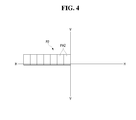
- FIG. 4 is a schematic view illustrating a beam pattern formed by a second lamp module according to the exemplary embodiment of the present disclosure
- FIG. 5 is a schematic view illustrating a beam pattern formed by a lamp component according to the exemplary embodiment of the present disclosure
- FIG. 6 is a schematic view illustrating a light irradiation range of the lamp component according to the exemplary embodiment of the present disclosure and an image acquisition range of an image acquisition component;
- FIG. 7 is a schematic view illustrating an angle between an instant vehicle and an opposite vehicle according to the exemplary embodiment of the present disclosure
- FIG. 8 is a schematic view illustrating an angle between the instant vehicle and a preceding vehicle according to the exemplary embodiment of the present disclosure
- FIG. 9 is a schematic view illustrating fixed ranges added to both sides of the front vehicle according to the exemplary embodiment of the present disclosure.
- FIGS. 10 and 11 are schematic views illustrating a shadow area according to a location of the opposite vehicle according to the exemplary embodiment of the present disclosure
- FIGS. 12 and 13 are schematic views illustrating a shadow area according to a location of the preceding vehicle according to the exemplary embodiment of the present disclosure
- FIG. 14 is a schematic view illustrating fixed ranges added to both sides of the front vehicle according to the exemplary embodiment of the present disclosure to have different widths;
- FIG. 15 is a schematic view illustrating the fixed ranges and variable ranges added to both sides of the front vehicle according to the exemplary embodiment of the present disclosure
- FIGS. 16 and 17 are schematic views illustrating an angle between the instant vehicle and the opposite vehicle according to the location of the opposite vehicle according to the exemplary embodiment of the present disclosure
- FIGS. 18 and 19 are schematic views illustrating a shadow area according to an angle variation rate of the opposite vehicle according to the exemplary embodiment of the present disclosure
- FIGS. 20 and 21 are schematic views illustrating an angle between the instant vehicle and the opposite vehicle according to the location of the preceding vehicle according to the exemplary embodiment of the present disclosure
- FIGS. 22 and 23 are schematic views illustrating a shadow area according to an angle variation rate of the preceding vehicle according to the exemplary embodiment of the present disclosure
- FIG. 24 is a schematic view illustrating a passing vehicle which enters the image acquisition range of the image acquisition component according to the exemplary embodiment of the present disclosure
- FIGS. 25 and 26 are schematic views illustrating a shadow area according to a location of the passing vehicle according to the exemplary embodiment of the present disclosure
- FIGS. 27 and 28 are schematic views illustrating variable ranges on the basis of an angle variation rate according to the exemplary embodiment of the present disclosure.
- FIG. 29 is a flow chart illustrating a method of controlling the lamp for a vehicle according to the exemplary embodiment of the present disclosure.
- exemplary embodiments which will be disclosed in the description will be described with reference to perspective views, cross-sectional views, side views, and/or schematic views which are ideal exemplary views of the present disclosure. Accordingly, shapes of the exemplary views may change based on a manufacturing technology, an allowable tolerance, and/or the like. Accordingly, the exemplary embodiments of the present disclosure are not limited to the particular shapes that are shown but include changes of shapes formed based on a manufacturing process. Further, in each of the views shown in the exemplary embodiments of the present disclosure, each of the elements may be expanded or downscaled in view of convenience of the description. The same reference symbols refer to the same or similar components throughout the description.
- FIG. 1 is a block diagram illustrating a lamp for a vehicle according to an exemplary embodiment of the present disclosure.
- a lamp for a vehicle 1 according to the exemplary embodiment of the present disclosure may include a lamp component 100 , an image acquisition component 200 , a recognition component 300 , a sensing component 400 , and a control component 500 .
- the lamp for a vehicle 1 is used as a head lamp capable of irradiating light in a driving direction of a vehicle to allow a front view of the vehicle to be secured when the vehicle is operated at night or through a dark place such as a tunnel or the like in the exemplary embodiment of the present disclosure
- the present disclosure is not limited thereto, and the lamp for a vehicle 1 may also be used as any of various lamps installed in a vehicle such as a tail lamp, a brake lamp, a fog lamp, a daytime driving lamp, a turn signal lamp, a position lamp, a backup lamp, and the like in addition to the head lamp.
- the lamp for a vehicle 1 may form a high beam pattern to secure a distant view in front of the vehicle, in which generation of glare toward a driver of a front vehicle may be prevented since a shadow area may be formed by reducing a light amount of light irradiated to an area that corresponds to a location of the front vehicle such as a preceding vehicle or an opposite vehicle or preventing light irradiation.
- the lamp for a vehicle 1 of the present disclosure may be installed together with a lamp configured to form a low beam pattern when forming a high beam pattern, and the lamp for a vehicle 1 of the present disclosure may be turned off when the low beam pattern is desired to be formed and may be turned on together with the lamp configured to form the low beam pattern when forming the high beam pattern.
- the lamp component 100 may generate light for forming a beam pattern suitable for a purpose of the lamp for a vehicle 1 of the present disclosure.
- FIG. 2 is a schematic view illustrating the lamp component according to the exemplary embodiment of the present disclosure.
- the lamp component 100 may include a first lamp module 110 and a second lamp module 120 , and in the exemplary embodiment of the present disclosure, the first lamp module 110 and the second lamp module 120 may each be installed at both sides of the vehicle to generate light suitable for a purpose of the head lamp.
- the first lamp module 110 may be installed at the right side of the front of the vehicle and the second lamp module 120 may be installed at the left side of the front of the vehicle.
- the first lamp module 110 may form a first beam pattern P 1 that includes a plurality of pattern areas PA 1 as shown in FIG. 3
- the second lamp module 120 may form a second beam pattern P 2 that includes a plurality of pattern areas PA 2 to be symmetric with the first beam pattern P 1 with respect to line V-V. Accordingly, a center of the front of the vehicle as shown in FIG. 4 , and the first beam pattern P 1 and the second beam pattern P 2 may be combined to form a beam pattern P suitable for the purpose of the lamp for a vehicle 1 of the present disclosure, e.g., a high beam pattern as shown in FIG. 5 .
- the present disclosure is not limited thereto, and the plurality of pattern areas PA 1 of the first beam pattern P 1 and the plurality of pattern areas PA 2 of the second beam pattern P 2 may be formed so that parts of the pattern areas which are close (e.g., adjacent) to each other may overlap each other, since an unnecessary shadow area may be formed when the pattern areas adjacent to each other are spaced apart from each other. Further, the first beam pattern P 1 and the second beam pattern P 2 may be formed to partially overlap each other at a center part of the beam pattern P to improve the brightness to improve a far-field view of the vehicle.
- the first lamp module 110 and the second lamp module 120 may include a plurality of light emitting areas (not shown) from which light for forming the plurality of pattern areas PA 1 and PA 2 is generated, and each of the plurality of light emitting areas may be understood as a light emitting surface of a light source, a light emitting lens, an emission surface of a light guide, or the like.
- the present disclosure is not limited thereto, and the number of the plurality of pattern areas PA 1 and PA 2 may be varied based on the shape or size of the beam pattern required to be suitable for the purpose of the lamp for a vehicle 1 of the present disclosure, and a part of the beam pattern P may have pattern areas disposed in rows different from rows of another part.
- first beam pattern P 1 and second beam pattern P 2 and the beam pattern P, which may be formed by combination of the first beam pattern P 1 and the second beam pattern P 2 , may be understood as beam patterns formed when light is irradiated on a screen disposed in front of the vehicle at a predetermined distance.
- At least one of the plurality of light emitting areas of the first lamp module 110 and the second lamp module 120 may be turned off based on the location of the front vehicle, and in this case, since light may be not generated from the light emitting area which is turned off, and thus at least one of the plurality of pattern areas PA 1 of the first beam pattern P 1 and the plurality of pattern areas PA 2 of the second beam pattern P 2 may be not formed, the shadow area may be formed.
- the present disclosure is not limited thereto, and a light amount of light generated from at least one of the plurality of light emitting areas of the first lamp module 110 and the second lamp module 120 may be decreased to form the shadow area.
- the image acquisition component 200 may include at least one camera capable of acquiring an image in front of the vehicle, and the number of cameras or a view angle of the camera may be varied based on an image acquisition range.
- the image acquisition component 200 may include an image acquisition range R 2 greater than a light irradiation range R 1 of the lamp component 100 to include the light irradiation range R 1 of the lamp component 100 since a shadow area of a front vehicle at a location out of the image acquisition range R 2 may be more difficult to form when the light irradiation range R 1 is greater than the image acquisition range R 2 .
- a shadow area may be formed based on a location of a passing vehicle by allowing the passing vehicle to be recognized before the vehicle passing from the rear thereof enters the light irradiation range R 1 .
- the image acquisition component 200 may acquire a forward view image at a predetermined period, and the period of acquiring the front image may vary based on a road environment or a operating velocity of the vehicle.
- the recognition component 300 may recognize the front vehicle from the front image acquired by the image acquisition component 200 .
- the recognition component 300 may recognize the location and width of the front vehicle, a distance to the front vehicle, the number of front vehicles, and the like from the forward view image on the basis of a wavelength or width of light generated from a head lamp of the opposite vehicle or a tail lamp of the preceding vehicle.
- the recognition component 300 may determine an angle between the instant vehicle and the front vehicle from the front image, and the number of angles determined by the recognition component 300 may be used by the control component 500 to determine the number of front vehicles.
- the instant vehicle may refer to the vehicle that includes a lamp for a vehicle according to exemplary embodiments of the present disclosure.
- the recognition component 300 may calculate the angle between the instant vehicle and the front vehicle with respect to a reference line parallel to a driving direction of the instant vehicle, and in the exemplary embodiment of the present disclosure, the image acquisition component 200 may be installed at a center of the instant vehicle and thus the reference line may pass through the center of the instant vehicle in the driving direction of the instant vehicle.
- the recognition component 300 may determine angles ⁇ 1 and ⁇ 2 which may be formed respectively between a reference line C which passes through a center of the instant vehicle V in a longitudinal direction of the instant vehicle V and a left head lamp and a right head lamp of an opposite vehicle VO when the opposite vehicle VO is disposed in front of the instant vehicle V as shown in FIG. 7 . Further, the recognition component 300 may determine angles ⁇ 3 and ⁇ 4 which may be formed respectively between a reference line C parallel to the longitudinal direction of the instant vehicle V and a left tail lamp and a right tail lamp of a preceding vehicle VP when the preceding vehicle VP is disposed in front of the instant vehicle V as shown in FIG. 8 .
- lateral sides of each the opposite vehicle VO and the preceding vehicle VP may be determined with respect to directions in which the opposite vehicle VO and the preceding vehicle VP are each viewed from the instant vehicle V.
- the lateral sides of the opposite vehicle VO may be viewed from the instant vehicle V and lateral sides with respect to a driving direction of the opposite vehicle VO may be opposite to each other.
- angles determined by the recognition component 300 may have a positive value or a negative value to indicate directions with respect to the reference line C parallel to the driving direction of the instant vehicle V, and an example is described in which an angle in a left direction with respect to the reference line C is indicated as a negative value, and an angle in a right direction with respect to the reference line C is indicated as a positive value.
- angles ⁇ 1 , ⁇ 2 , and ⁇ 3 may be understood as angles in the left direction with respect to the reference line C
- the angle ⁇ 4 may be understood as an angle in the right direction with respect to the reference line C
- a case in which an angle of the front vehicle increases or decreases may be understood as a case in which an angle between the front vehicle and the reference line C increases or decreases.
- the sensing component 400 may sense various states of the vehicle, and in the exemplary embodiment of the present disclosure, although an example is described in which the sensing component 400 includes a velocity sensing module 410 configured to sense the driving velocity of the vehicle, a lighting mode sensing module 420 configured to sense a lighting mode, and a brightness sensing module 430 configured to sense surrounding brightness, the present disclosure is not limited thereto, and the sensing component 400 may sense various states required to control the lamp component 100 .
- the velocity sensing module 410 may sense the driving velocity of the vehicle by a vehicle velocity sensor, an acceleration sensor, a GPS sensor, or the like, the lighting mode sensing module 420 may sense a lighting mode selected by operation signals (e.g., positions) of a lighting switch, a lever, or the like provided in the vehicle, and the brightness sensing module 430 may sense brightness around the vehicle by an illuminance sensor or the like.
- the lighting mode may include a first mode for forming the low beam pattern, a second mode for forming the high beam pattern, and a third mode which adjusts the beam pattern based on a driving environment of the vehicle, and the lighting mode sensing module 420 may sense at least one mode among the above-described first to third modes.
- the third mode may be understood as an automatic mode, e.g., a mode which may automatically adjust the beam pattern based on the driving environment of the vehicle to form a shadow area based on the location of the front vehicle when the low beam pattern or the high beam pattern is formed.
- the lighting mode includes the first to third modes
- the present disclosure is not limited thereto, and the lighting mode may be varied based on the type of the beam pattern.
- the control component 500 may control the lamp component 100 and form the shadow area to prevent or reduce the generation of the glare toward the driver of the front vehicle based on the location of the front vehicle when the front vehicle is recognized by the recognition component 300 .
- the control component 500 may control the lamp component 100 to form the shadow area when both the second mode and the third mode are selected together as the lighting mode, since the lamp component 100 forms the high beam pattern and automatically forms the shadow area based on the location of the front vehicle in the embodiment of the present disclosure.
- the control component 500 may output control signals which control brightness of light generated from at least one of the plurality of light emitting areas of the first lamp module 110 and the second lamp module 120 , and the control signals output from the control component 500 may adjust currents applied to a light source of each of the first lamp module 110 and the second lamp module 120 to turn on or turn off the light source or adjust an amount of the light output. Depending on the type of the light source, the amount of the light output may be varied by decreasing the generated lighted amount and/or deflecting a portion of the generated light to different directions. In the exemplary embodiment of the present disclosure, the control component 500 may turn off at least one of the plurality of light emitting areas of the first lamp module 110 and the second lamp module 120 to form the shadow area.
- the control component 500 may allow the shadow area to be formed in a width that corresponds to a width of the front vehicle, and also a predetermined fixed range may be added to at least one of both sides of the front vehicle based on the location of the front vehicle.
- the control component 500 may allow the shadow area to be formed in the width of front vehicle with respect to the range with the fixed range added, to prevent the generation of the glare toward the driver of the front vehicle by securing a buffer space (e.g., operational margin) in the shadow area, since the front vehicle may also move during a time while the recognition component 300 recognizes the front vehicle from the forward view image acquired by the image acquisition component 200 and the control component 500 controls the lamp component 100 to form the shadow area based on the location of the recognized front vehicle.
- a buffer space e.g., operational margin
- the control component 500 when the control component 500 forms a shadow area based on the width of the front vehicle, since glare toward the driver of the front vehicle may be generated when the front vehicle moves out of the shadow area while the control component 500 controls the lamp component 100 , the generation of the glare toward the driver of the front vehicle may be prevented by adding the predetermined fixed ranges to both sides of the front vehicle front in consideration of movement of the vehicle.
- control component 500 may add fixed ranges Ws, each having a predetermined width from both sides of the opposite vehicle, to a width Wc of the opposite vehicle VO as shown in FIG. 9 and may turn off a light emitting area that forms a pattern area which includes at least a part of each of a width Wc and fixed ranges Ws of the front vehicle among the plurality of pattern areas PA 1 and PA 2 included in the beam pattern P, to form a shadow area S as shown in FIGS. 10 and 11 . Further, as shown in FIGS.
- control component 500 may turn off a light emitting area that forms a pattern area which includes at least a part of each of a width Wc and fixed ranges Ws of the preceding vehicle VP among the plurality of pattern areas PA 1 and PA 2 , to form the shadow area S.
- the fixed ranges added to both sides of the front vehicle may have different widths based on the location of the front vehicle. For example, as shown in FIG. 14 , in the opposite vehicle disposed in front of the instant vehicle, the fixed range in a direction in which an opposite vehicle is disposed may have a greater width than the other fixed range with respect to the instant vehicle which is capable of causing direct glare to a driver of the opposite vehicle. In FIG. 14 , although an example is described in which the fixed ranges added to both sides of the opposite vehicle are different from each other, fixed ranges added to both sides of the preceding vehicle may also have different widths like those of the opposite vehicle.
- the control component 500 may output control signals to control the lamp component 100 when the driving velocity of the vehicle is greater than or equal to a first reference velocity as a sensing result of the velocity sensing module 410 and may turn off the lamp component 100 when the driving velocity of the vehicle is less than a second reference velocity which is less than the first reference velocity.
- the control component 500 may allow the far-field view to be secured and the shadow area to be formed based on the location of the front vehicle when the driving velocity of the vehicle is greater than or equal to the first reference velocity which is a relatively high velocity.
- the control component 500 may turn off the lamp component 100 when the driving velocity of the vehicle is less than the second reference velocity which is a relatively low velocity since securing the distant view may be less important at low vehicle velocities.
- control component 500 may maintain a state in which the lamp component 100 is turned on when the driving velocity of the vehicle increases to be greater than or equal to the first reference velocity and then decreases to a velocity between the first reference velocity and the second reference velocity after the lamp component 100 is turned on, and may turn off the lamp component 100 when the driving velocity of the vehicle decreases to be less than the second reference velocity.
- control component 500 may control the lamp component 100 when the number of front vehicles recognized by the recognition component 300 is smaller than or equal to a predetermined number, since almost every light emitting area included in the lamp component 100 may be required to be turned off, and thus effects such as prevention of the glare by the forming of the shadow area and the like may be difficult to acquire when the number of front vehicles is greater than the predetermined number.
- the number of front vehicles to which the control component 500 turns off the lamp component 100 may be varied based on a width in which the beam pattern is formed, the road environment, or the like, the lamp component 100 may be turned on when the number of front vehicles is smaller than or equal to, for example, eight, and the lamp component 100 may be turned off when the number of front vehicles is greater than or equal to, for example, nine.
- control component 500 may turn on the lamp component 100 to form the shadow area based on the location of the front vehicle when the surrounding brightness of the vehicle is lower than or equal to standard reference brightness, and since an effect of preventing the generation of the glare may be difficult to acquire, the control component 500 may turn off the lamp component 100 when the surrounding brightness of the vehicle is greater than the reference brightness.
- control component 500 may form the shadow area at the at least one of both sides of the front vehicle in addition to the fixed ranges Ws with respect to a scope to which variable ranges Wv, having widths that vary by an angle variation rate based on the location of the front vehicle, e.g., variation of the angle between the instant vehicle and the front vehicle at a predetermined period, may be added.
- variable ranges Wv are added to both sides of the front vehicle
- present disclosure is not limited thereto, and widths of the variable ranges Wv applied to respective sides of the front vehicle may increase or decrease based on an angle variation rate between the instant vehicle and the front vehicle, and when the variable ranges Wv decrease, the above-described fixed ranges Ws may also decrease.
- a case in which the shadow area is formed becomes excessive or insufficient based on the location of the front vehicle may be prevented.
- the shadow area may become insufficient when the front vehicle becomes close, and when the fixed ranges Ws have relatively large widths, the shadow area may be formed excessively when the front vehicle becomes distant.
- an adjusted (e.g., optimum) shadow area may be formed through the variable ranges Wv, which has the widths that vary by the angle variation rate between the instant vehicle and the front vehicle, in the exemplary embodiment of the present disclosure.
- the control component 500 may calculate an angle variation rate through differences between angles ⁇ 11 and ⁇ 21 formed respectively by the left head lamp and the right head lamp of the opposite vehicle VO with respect to the reference line C of the instant vehicle V at a previous time step with respect to a predetermined period as shown in FIG. 16 , and angles ⁇ 12 and ⁇ 22 formed respectively by the left head lamp and the right head lamp of the opposite vehicle VO with respect to the reference line C of the instant vehicle V at the present time step as shown in FIG. 17 , and when the angle variation rate is greater than or equal to a threshold value, the widths of the variable ranges Wv to be added to both sides of the opposite vehicle VO at a next time step with respect to the predetermined period may be determined.
- control component 500 may determine that the opposite vehicle VO moves in a left direction with respect to the instant vehicle V when differences between the angles at the present time step and the angles between the previous time step, that is, ⁇ 12 ⁇ ( ⁇ 11 ) and ⁇ 22 ⁇ ( ⁇ 21 ) have negative values with respect to the present time step, and may determine that the shadow area may be difficult to be formed sufficiently at the above-described fixed ranges Ws when the differences are greater than or equal to the threshold value. In this case, to the control component 500 may form the shadow area at the next time step with respect to a range in which the variable range Wv is added to the left side of the opposite vehicle VO in addition to the fixed range Ws.
- the case in which the angle variation rate of the opposite vehicle VO between the previous time step and the present time step is greater than or equal to the threshold value may be understood as a case in which a driving velocity of at least one of the instant vehicle V or the opposite vehicle VO increases and thus a distance between the instant vehicle V and the opposite vehicle VO decreases, and in this case, since location variation of the opposite vehicle VO may be relatively larger, the variable ranges Wv may be added to the fixed ranges Ws to prevent generation of glare toward a driver of the opposite vehicle VO at the next time step. Since the variable range Wv may decrease to the fixed range Ws at the right side of the opposite vehicle VO, the right side of the front vehicle may have the fixed range Ws added thereto without the variable range Wv.
- the control component 500 may turn off the light emitting area that forms the pattern area, which includes the width We of the opposite vehicle VO, the fixed ranges Ws added to both sides of the opposite vehicle VO, and the variable range Wv added to the left side of the opposite vehicle VO among the plurality of pattern areas PA 1 and PA 2 , included in the beam pattern P to form the shadow area S at the next time step as shown in FIGS. 18 and 19 .
- the shadow area at the left side of the opposite vehicle VO may have a relatively larger width than the width of the shadow area at the right side.
- the side of the on-coming opposite vehicle may vary depending on the road usage customs and regulations.
- control component 500 may calculate an angle variation rate through differences, that is, ⁇ 42 ⁇ 41 and ⁇ 32 ⁇ ( ⁇ 31 ) between angles ⁇ 31 and ⁇ 41 each formed by the left tail lamp and the right tail lamp of the preceding vehicle VP with respect to the reference line C of the instant vehicle V at a previous time step with respect to a predetermined period as shown in FIG. 20 and angles ⁇ 32 and ⁇ 42 each formed by the left tail lamp and the right tail lamp of the preceding vehicle VP with respect to the reference line C of the instant vehicle V at the present time step as shown in FIG. 21 .
- the angle variation rate is greater than or equal to a threshold value
- the widths of the variable ranges Wv to be added to both sides of the preceding vehicle VP at a next time step with respect to the predetermined period may be determined.
- a distance between the instant vehicle V and the preceding vehicle VP may decrease when the driving velocity of the instant vehicle V is greater than the driving velocity of the preceding vehicle VP, which is in a same driving lane as the instant vehicle V.
- the angle formed by the left tail lamp of the preceding vehicle VP and the reference line C of the instant vehicle V may increase in a negative direction
- the angle formed by the right tail lamp of the preceding vehicle VP and the reference line C of the instant vehicle V may increase in a positive direction.
- the control component 500 may add the variable range Wv to a left side of the preceding vehicle VP when a difference between the angle of the left tail lamp of the preceding vehicle VP at the present time step and the angle of the left tail lamp of the preceding vehicle VP at the previous time step with respect to the present time step has a negative value and is greater than or equal to the threshold value.
- the control component 500 may add the variable range Wv to a right side of the preceding vehicle VP when a difference between the angle of the right tail lamp of the preceding vehicle VP at the present time step and the angle of the right tail lamp of the preceding vehicle VP at the previous time step has a positive value and is greater than or equal to the threshold value.
- a negative value is greater than a threshold value may be understood to mean that an absolute value of the negative value is greater than an absolute value of the threshold value.
- ⁇ 2 degrees may be said to be greater than a threshold value of 1 degree or ⁇ 1 degree.
- a case in which an angle variation rate of the preceding vehicle VP between the previous time step and the present time step is greater than or equal to the threshold value may be understood as a case in which the driving velocity of the instant vehicle V is faster than the driving velocity of the preceding vehicle VP, and thus a distance between the instant vehicle V and the preceding vehicle VP decreases.
- the variable ranges Wv may be added to the fixed ranges Ws to prevent generation of glare toward a driver of the preceding vehicle VP at the next time step.
- a light emitting area that forms the pattern area which includes at least a part of each of the width We of the preceding vehicle VP, the fixed ranges Ws added to both sides of the preceding vehicle VP, and the variable ranges Wv added to both sides of the preceding vehicle VP among the plurality of pattern areas PA 1 and PA 2 included in the beam pattern P may be turned off to form a shadow area, which may have a greater range than the range of the shadow area formed when only the fixed ranges Ws are added, at the next time step as shown in FIG. 22 and FIG. 23 .
- the adjusted shadow area may be formed when the distance between the instant vehicle and the front vehicle increases or decreases.
- the light irradiation range R 1 of the lamp component 100 is smaller than the image acquisition range R 2 of the image acquisition component 200 , a passing vehicle VB which passes the instant vehicle V from the rear may be sensed before entering the light irradiation range R 1 as shown in FIG. 24 .
- the shadow area S may be formed without glare when the passing vehicle VB passes the instant vehicle V as shown in FIGS. 25 and 26 , and the adjusted shadow area may be formed by the above-described fixed ranges Ws and variable ranges Wv when the passing vehicle VB is disposed in front of the instant vehicle V.
- variable ranges Wv may be added when the angle variation rate is greater than or equal to the threshold value, and in the exemplary embodiment of the present disclosure, as shown in FIGS. 27 and 28 , an example is described in which the variable ranges Wv increase linearly when the angle variation rate is greater than or equal to 0.05 and ⁇ 0.05, which may be the threshold values, and the variable ranges Wv may be indicated as a light irradiation angle.
- variable ranges Wv and the angle variation rate may each have the positive value or the negative value to indicate directions with respect to the center of the instant vehicle.
- FIG. 27 is an example in which the variable range Wv added to the right side of the front vehicle when the front vehicle moves in a right direction with respect to the instant vehicle
- FIG. 28 is an example in which the variable range Wv added to the left side of the front vehicle when the front vehicle moves in a left direction with respect to the instant vehicle.
- variable ranges Wv may be determined based on the above-described FIG. 28 , and since the left tail lamp of the preceding vehicle moves in a left direction when moving closer to the instant vehicle, and the right tail lamp moves in a right direction when moving closer to the instant vehicle, the variable ranges Wv may be determined based on the above-described FIGS. 27 and 28 .
- the angle variation rate is divided into a plurality of sections when the angle variation rate is greater than or equal to the threshold value, and increasing rates of the variable ranges are different at two sections adjacent to each other, since the above is merely an example for understanding the present disclosure, the increasing rates of the variable ranges may be the same at every section when the angle variation rate is greater than or equal to the threshold value.
- FIG. 29 is a flow chart that illustrates a method of controlling the lamp for a vehicle according to the exemplary embodiment of the present disclosure.
- the method of controlling the lamp for a vehicle according to the exemplary embodiment of the present disclosure may include sensing a lighting mode, and subsequently determining whether the sensed lighting mode satisfies a condition for forming a shadow area (S 110 ).
- the lamp for a vehicle may form a high beam pattern and form the shadow area based on the location of the front vehicle and whether the second mode and the third mode among the above-described first to third modes are selected together may be sensed.
- the driving velocity of the vehicle may be sensed, and whether the sensed driving velocity satisfies the condition for forming the shadow area may be determined (S 120 ). In other words, when the driving velocity of the vehicle is greater than or equal to the first reference velocity in which securing the distant view of the vehicle is required, the lamp component 100 may be turned on.
- the number of front vehicles may be determined (S 140 ) to turn off the lamp component 100 since almost every light emitting area may require to be turned off to form the shadow area when the number of front vehicles is greater than or equal to the predetermined number.
- the order of operations S 110 to S 140 may be varied, and when all of operations S 110 to S 140 are satisfied, the shadow area may be formed by lighting the lamp component 100 and then adding the fixed range Ws or the fixed range Ws and the variable range Wv to at least one of both sides of the front vehicle in addition to the width of the front vehicle (S 150 ). Furthermore, when at least one of the above-described operations S 110 to S 140 is satisfied, the lamp component 100 may be turned off (S 160 ).
- the lamp for a vehicle of the present disclosure may form the shadow area by adding the fixed ranges to the width of the front vehicle or by adding the fixed ranges and the variable ranges to the width of the front vehicle based on the angle variation rate of the front vehicle to adjust the shadow area when a relative location between the instant vehicle and the front vehicle changes.
- the above-described lamp for a vehicle of the present disclosure may achieve at least one of the following effects. Since a shadow area is formed at an area that corresponds to a location of a front vehicle based on a lighting mode selected by a driver, driver convenience may be improved. Further, since the shadow area is formed based on fixed ranges added to both sides of the front vehicle, glare may be prevented when the front vehicle moves out of the shadow area due to a time delay while recognizing the front vehicle and forming the shadow area. In addition, since a shadow area is formed based on a variable range added to at least one of both sides of the front vehicle to have a width which may be varied based on an angle variation rate of the front vehicle, an adjusted shadow area may be formed when location of the front vehicle varies.
Landscapes
- Engineering & Computer Science (AREA)
- Mechanical Engineering (AREA)
- Lighting Device Outwards From Vehicle And Optical Signal (AREA)
Abstract
Description
Claims (11)
Applications Claiming Priority (4)
| Application Number | Priority Date | Filing Date | Title |
|---|---|---|---|
| KR10-2017-0154236 | 2017-11-17 | ||
| KR10-2017-0154235 | 2017-11-17 | ||
| KR1020170154235A KR101982503B1 (en) | 2017-11-17 | 2017-11-17 | Lamp for vehicle |
| KR1020170154236A KR101917211B1 (en) | 2017-11-17 | 2017-11-17 | Lamp for vehicle |
Publications (2)
| Publication Number | Publication Date |
|---|---|
| US20190152378A1 US20190152378A1 (en) | 2019-05-23 |
| US10434930B2 true US10434930B2 (en) | 2019-10-08 |
Family
ID=66336376
Family Applications (1)
| Application Number | Title | Priority Date | Filing Date |
|---|---|---|---|
| US16/190,639 Active US10434930B2 (en) | 2017-11-17 | 2018-11-14 | Lamp for vehicle |
Country Status (3)
| Country | Link |
|---|---|
| US (1) | US10434930B2 (en) |
| CN (1) | CN109798491B (en) |
| DE (1) | DE102018219613A1 (en) |
Families Citing this family (8)
| Publication number | Priority date | Publication date | Assignee | Title |
|---|---|---|---|---|
| JP7287979B2 (en) * | 2018-09-25 | 2023-06-06 | 株式会社小糸製作所 | Lighting systems and vehicle lighting |
| GB2581780B (en) * | 2019-02-21 | 2021-09-08 | Jaguar Land Rover Ltd | Apparatus and method for driving beam control |
| KR102929655B1 (en) | 2020-10-27 | 2026-02-20 | 현대자동차주식회사 | Headlamp controlling system and method for automotive |
| JP7626655B2 (en) * | 2021-04-16 | 2025-02-04 | スタンレー電気株式会社 | Vehicle position determining device, vehicle position determining method, light distribution control device, and vehicle lighting system |
| DE112022006292B4 (en) * | 2022-03-17 | 2025-05-22 | Mitsubishi Electric Corporation | Light intensity distribution control device |
| JP7754112B2 (en) * | 2023-01-19 | 2025-10-15 | トヨタ自動車株式会社 | Light distribution control device |
| FR3145323B1 (en) * | 2023-01-27 | 2025-01-10 | Psa Automobiles Sa | Method and device for controlling an on-board lighting system in a vehicle based on the acceleration of the limits of a detected object. |
| FR3145322A1 (en) * | 2023-01-27 | 2024-08-02 | Psa Automobiles Sa | Method and device for controlling an on-board lighting system in a vehicle. |
Citations (4)
| Publication number | Priority date | Publication date | Assignee | Title |
|---|---|---|---|---|
| EP2281719A1 (en) | 2009-08-04 | 2011-02-09 | Koito Manufacturing Co., Ltd. | Light distribution control system for automotive headlamp |
| US20160167566A1 (en) * | 2013-07-11 | 2016-06-16 | Koito Manufacturing Co., Ltd. | Light distribution control method and light distribution control device for a vehicular headlamp |
| US20160250964A1 (en) | 2015-02-27 | 2016-09-01 | Toyota Jidosha Kabushiki Kaisha | Vehicle headlight control device |
| US20180137375A1 (en) * | 2015-07-17 | 2018-05-17 | Hitachi Automotive Systems, Ltd. | Onboard environment recognition device |
Family Cites Families (2)
| Publication number | Priority date | Publication date | Assignee | Title |
|---|---|---|---|---|
| JP6001238B2 (en) * | 2011-02-14 | 2016-10-05 | 株式会社小糸製作所 | Light distribution control device for vehicle headlamp |
| JP2014004922A (en) * | 2012-06-25 | 2014-01-16 | Denso Corp | Head lamp light distribution control device for vehicle |
-
2018
- 2018-11-14 US US16/190,639 patent/US10434930B2/en active Active
- 2018-11-15 CN CN201811356241.4A patent/CN109798491B/en active Active
- 2018-11-16 DE DE102018219613.3A patent/DE102018219613A1/en active Pending
Patent Citations (6)
| Publication number | Priority date | Publication date | Assignee | Title |
|---|---|---|---|---|
| EP2281719A1 (en) | 2009-08-04 | 2011-02-09 | Koito Manufacturing Co., Ltd. | Light distribution control system for automotive headlamp |
| JP2011031807A (en) | 2009-08-04 | 2011-02-17 | Koito Mfg Co Ltd | Light distribution control system for vehicular headlamp |
| US20160167566A1 (en) * | 2013-07-11 | 2016-06-16 | Koito Manufacturing Co., Ltd. | Light distribution control method and light distribution control device for a vehicular headlamp |
| US20160250964A1 (en) | 2015-02-27 | 2016-09-01 | Toyota Jidosha Kabushiki Kaisha | Vehicle headlight control device |
| JP2016159709A (en) | 2015-02-27 | 2016-09-05 | トヨタ自動車株式会社 | Vehicular headlamp control unit |
| US20180137375A1 (en) * | 2015-07-17 | 2018-05-17 | Hitachi Automotive Systems, Ltd. | Onboard environment recognition device |
Also Published As
| Publication number | Publication date |
|---|---|
| US20190152378A1 (en) | 2019-05-23 |
| CN109798491A (en) | 2019-05-24 |
| CN109798491B (en) | 2021-05-07 |
| DE102018219613A1 (en) | 2019-05-23 |
Similar Documents
| Publication | Publication Date | Title |
|---|---|---|
| US10434930B2 (en) | Lamp for vehicle | |
| US8847492B2 (en) | Lighting control device for vehicle headlamp, and vehicle headlamp system | |
| EP3020602B1 (en) | Light distribution control method and light distribution control device for vehicular head lamp | |
| CN102897083B (en) | The light distribution control of head light | |
| EP1970249A2 (en) | Vehicle operation support method and system | |
| US20150149045A1 (en) | Vehicle headlamp light distribution control apparatus | |
| CN104619556B (en) | Method for controlling adaptive illuminator | |
| CN105922928A (en) | Vehicle headlight control device | |
| US9199573B2 (en) | Vehicle light distribution control device and vehicle light distribution control method | |
| CN107009950A (en) | Lamps apparatus for vehicle and the method for controlling the lamps apparatus for vehicle | |
| US20130335984A1 (en) | Method and Device for Operating a Headlamp for a Motor Vehicle | |
| EP4227158B1 (en) | Front headlamp control system and control method thereof | |
| KR102397537B1 (en) | Lamp for vehicle | |
| KR102394952B1 (en) | Lamp for vehicle and controlling method applied to the same | |
| KR102619772B1 (en) | lamp for vehicle | |
| JP2017177941A (en) | Cast light controlling apparatus for vehicle | |
| WO2019156087A1 (en) | Image processing device and vehicle light fixture | |
| US20250026260A1 (en) | Headlamp auto-leveling control system and method thereof | |
| KR101982503B1 (en) | Lamp for vehicle | |
| US20240294112A1 (en) | Vehicle headlamp | |
| KR20160059681A (en) | Lamp for vehicle | |
| KR20150134794A (en) | Lamp for vehicle and controlling method foe the same | |
| KR101917211B1 (en) | Lamp for vehicle | |
| JP6162012B2 (en) | Lighting control device for vehicle headlamp, vehicle headlamp system | |
| KR20200048900A (en) | lamp for vehicle |
Legal Events
| Date | Code | Title | Description |
|---|---|---|---|
| AS | Assignment |
Owner name: SL CORPORATION, KOREA, REPUBLIC OF Free format text: ASSIGNMENT OF ASSIGNORS INTEREST;ASSIGNORS:KIM, DAEHYUN;BAE, YONG DEOK;PARK, JAEJOON;AND OTHERS;REEL/FRAME:047500/0122 Effective date: 20181113 |
|
| FEPP | Fee payment procedure |
Free format text: ENTITY STATUS SET TO UNDISCOUNTED (ORIGINAL EVENT CODE: BIG.); ENTITY STATUS OF PATENT OWNER: LARGE ENTITY |
|
| STPP | Information on status: patent application and granting procedure in general |
Free format text: NON FINAL ACTION MAILED |
|
| STPP | Information on status: patent application and granting procedure in general |
Free format text: RESPONSE TO NON-FINAL OFFICE ACTION ENTERED AND FORWARDED TO EXAMINER |
|
| STPP | Information on status: patent application and granting procedure in general |
Free format text: NOTICE OF ALLOWANCE MAILED -- APPLICATION RECEIVED IN OFFICE OF PUBLICATIONS |
|
| STPP | Information on status: patent application and granting procedure in general |
Free format text: PUBLICATIONS -- ISSUE FEE PAYMENT VERIFIED |
|
| STCF | Information on status: patent grant |
Free format text: PATENTED CASE |
|
| MAFP | Maintenance fee payment |
Free format text: PAYMENT OF MAINTENANCE FEE, 4TH YEAR, LARGE ENTITY (ORIGINAL EVENT CODE: M1551); ENTITY STATUS OF PATENT OWNER: LARGE ENTITY Year of fee payment: 4 |