US10428675B2 - System for the active setting of a radial clearance size and aircraft engine with a system for the active setting of a radial clearance size - Google Patents
System for the active setting of a radial clearance size and aircraft engine with a system for the active setting of a radial clearance size Download PDFInfo
- Publication number
- US10428675B2 US10428675B2 US15/234,760 US201615234760A US10428675B2 US 10428675 B2 US10428675 B2 US 10428675B2 US 201615234760 A US201615234760 A US 201615234760A US 10428675 B2 US10428675 B2 US 10428675B2
- Authority
- US
- United States
- Prior art keywords
- housing
- radial clearance
- aircraft engine
- behavior
- chosen
- Prior art date
- Legal status (The legal status is an assumption and is not a legal conclusion. Google has not performed a legal analysis and makes no representation as to the accuracy of the status listed.)
- Active, expires
Links
Images


Classifications
-
- F—MECHANICAL ENGINEERING; LIGHTING; HEATING; WEAPONS; BLASTING
- F01—MACHINES OR ENGINES IN GENERAL; ENGINE PLANTS IN GENERAL; STEAM ENGINES
- F01D—NON-POSITIVE DISPLACEMENT MACHINES OR ENGINES, e.g. STEAM TURBINES
- F01D11/00—Preventing or minimising internal leakage of working-fluid, e.g. between stages
- F01D11/08—Preventing or minimising internal leakage of working-fluid, e.g. between stages for sealing space between rotor blade tips and stator
- F01D11/14—Adjusting or regulating tip-clearance, i.e. distance between rotor-blade tips and stator casing
- F01D11/20—Actively adjusting tip-clearance
- F01D11/24—Actively adjusting tip-clearance by selectively cooling-heating stator or rotor components
-
- F—MECHANICAL ENGINEERING; LIGHTING; HEATING; WEAPONS; BLASTING
- F04—POSITIVE - DISPLACEMENT MACHINES FOR LIQUIDS; PUMPS FOR LIQUIDS OR ELASTIC FLUIDS
- F04D—NON-POSITIVE-DISPLACEMENT PUMPS
- F04D29/00—Details, component parts, or accessories
- F04D29/58—Cooling; Heating; Diminishing heat transfer
- F04D29/582—Cooling; Heating; Diminishing heat transfer specially adapted for elastic fluid pumps
-
- F—MECHANICAL ENGINEERING; LIGHTING; HEATING; WEAPONS; BLASTING
- F04—POSITIVE - DISPLACEMENT MACHINES FOR LIQUIDS; PUMPS FOR LIQUIDS OR ELASTIC FLUIDS
- F04D—NON-POSITIVE-DISPLACEMENT PUMPS
- F04D29/00—Details, component parts, or accessories
- F04D29/60—Mounting; Assembling; Disassembling
- F04D29/64—Mounting; Assembling; Disassembling of axial pumps
- F04D29/642—Mounting; Assembling; Disassembling of axial pumps by adjusting the clearances between rotary and stationary parts
-
- F—MECHANICAL ENGINEERING; LIGHTING; HEATING; WEAPONS; BLASTING
- F05—INDEXING SCHEMES RELATING TO ENGINES OR PUMPS IN VARIOUS SUBCLASSES OF CLASSES F01-F04
- F05D—INDEXING SCHEME FOR ASPECTS RELATING TO NON-POSITIVE-DISPLACEMENT MACHINES OR ENGINES, GAS-TURBINES OR JET-PROPULSION PLANTS
- F05D2220/00—Application
- F05D2220/30—Application in turbines
- F05D2220/32—Application in turbines in gas turbines
- F05D2220/323—Application in turbines in gas turbines for aircraft propulsion, e.g. jet engines
-
- F—MECHANICAL ENGINEERING; LIGHTING; HEATING; WEAPONS; BLASTING
- F05—INDEXING SCHEMES RELATING TO ENGINES OR PUMPS IN VARIOUS SUBCLASSES OF CLASSES F01-F04
- F05D—INDEXING SCHEME FOR ASPECTS RELATING TO NON-POSITIVE-DISPLACEMENT MACHINES OR ENGINES, GAS-TURBINES OR JET-PROPULSION PLANTS
- F05D2260/00—Function
- F05D2260/30—Retaining components in desired mutual position
-
- F—MECHANICAL ENGINEERING; LIGHTING; HEATING; WEAPONS; BLASTING
- F05—INDEXING SCHEMES RELATING TO ENGINES OR PUMPS IN VARIOUS SUBCLASSES OF CLASSES F01-F04
- F05D—INDEXING SCHEME FOR ASPECTS RELATING TO NON-POSITIVE-DISPLACEMENT MACHINES OR ENGINES, GAS-TURBINES OR JET-PROPULSION PLANTS
- F05D2260/00—Function
- F05D2260/81—Modelling or simulation
-
- F—MECHANICAL ENGINEERING; LIGHTING; HEATING; WEAPONS; BLASTING
- F05—INDEXING SCHEMES RELATING TO ENGINES OR PUMPS IN VARIOUS SUBCLASSES OF CLASSES F01-F04
- F05D—INDEXING SCHEME FOR ASPECTS RELATING TO NON-POSITIVE-DISPLACEMENT MACHINES OR ENGINES, GAS-TURBINES OR JET-PROPULSION PLANTS
- F05D2270/00—Control
- F05D2270/30—Control parameters, e.g. input parameters
- F05D2270/303—Temperature
Definitions
- the invention relates to a system for the active setting of a radial clearance size as well as to an aircraft engine.
- TCC tip clearance control
- the setting i.e. the regulation or control of the cooling
- EEC engine computer
- Systems that are modulatable in a fully modular manner are operated by means of a method in which the actual clearance is either measured or calculated by the engine computer.
- the actual clearance that is thus determined is compared to the target clearance, and the housing cooling is adjusted correspondingly by the control system.
- the target clearance is set to be zero when the aircraft engine provides maximum thrust.
- the value for the target clearance can be higher than zero when the aircraft engine runs in the partial-load range. In this case, a sudden increase in thrust leads to a closure of the clearance, which cannot be compensated for fast enough by the reduced housing cooling, that is, it cannot keep the clearance constant. In this case, a target clearance that is too small would lead to a grazing contact.
- the system has a model-based setting device, wherein the time-dependent clearance size can be approximated by the model-based setting device, with only those influencing variables being taken into account that have a time-dependent deformation behavior (e.g., elongation behavior) that is equal to or slower than the time-dependent deformation behavior of the housing (e.g., elongation behavior), wherein the clearance size in the cold state serves as the set point, with that clearance size being reduced by at least one previously saved value of a clearance proportion that is determined at maximal thrust of the aircraft engine, and wherein a control variable for a cooling system of the housing can be determined by the model-based controller.
- a time-dependent deformation behavior e.g., elongation behavior
- the clearance size in the cold state serves as the set point, with that clearance size being reduced by at least one previously saved value of a clearance proportion that is determined at maximal thrust of the aircraft engine, and wherein a control variable for a cooling system of the housing can be determined by the model-based controller.
- the model-based setting device for the influencing variables has a relationship for the thermal behavior of at least one rotor disc of a compressor stage and/or turbine stage and a relationship for the thermal behavior of the housing.
- the model-based setting device for the influencing variables comprises only relationships for the thermal behavior of at least one rotor disc of a compressor stage and/or turbine stage and the thermal behavior of the housing.
- An efficient embodiment for the model-based setting device models the dynamic deformation behavior of structural components through step responses of the first order.
- the set point of the clearance size can be determined exclusively based on values that are independent of the current thrust state of the aircraft engine. This independence can particularly be achieved by respectively determining the clearance proportions that are caused by the mechanical and thermal deformation behavior of a blade, the mechanical deformation behavior of a rotor disc, the thermal deformation behavior of an inlet device (e.g., of a liner, or a segment comprising a liner) and/or the mechanical deformation behavior of a housing at maximal thrust.
- the housing has at least one inlet device, in particular a liner, or a segment comprising a liner.
- calculated and/or measured values for the temperature, the pressure, the speed and/or the rotational speed are used in determining the control variable. In this way, further values are available for determining the control variable.
- FIG. 1 shows a schematic rendering of an aircraft engine.
- FIG. 2 shows a schematic rendering of a clearance and of the setting of the clearance size.
- FIG. 3 shows a schematic rendering of an embodiment of the system for setting the clearance size.
- FIG. 4 shows a schematic rendering of possible or actual radial positions of the clearance changes at the rotor side and the housing side.
- FIG. 5 shows a schematic rendering of different operational states.
- FIG. 1 a per se known aircraft engine 100 is shown in a schematic manner, in which air L flows into the aircraft engine 100 from the front.
- the larger part of the inflowing air L is guided through the bypass channel 101 and is discharged in an accelerated state at the rear end of the aircraft engine 100 .
- a smaller part of the inflowing air L is conveyed into the core engine 102 and is compressed there inside a compressor with multiple compressor stages 11 .
- the compressed air is supplied to the combustion chambers 103 , wherein the compressed and heated-up air is then supplied to a turbine with turbine stages 12 , wherein the air subsequently flows out in an accelerated state at the rear end of the aircraft engine 100 .
- FIG. 1 The rotating rotor blades 13 of the compressor stages 11 and of the turbine stages 12 are surrounded by a housing 10 , with more details being shown in FIG. 2 . It is to be understood that the rendering of FIG. 1 is merely exemplary in nature. The embodiments that are described in the following can also be used in connection with other engine designs.
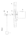
- FIG. 2 shows a section of the housing 10 .
- a rotor blade 15 is arranged on a rotor disc, with the rotor blade tip 13 being oriented radially towards the housing 10 .
- a liner 14 is arranged inside the housing 10 opposite the rotor blade tip 13 .
- the liner 14 is arranged in a segment that is subsequently connected to the housing.
- the radial clearance with the clearance size S is located between the rotor blade tip 13 and the housing 10 , and here in particular between the liner 14 .
- a cooling system 200 is used in a per se known manner, by means of which cooling air K can be applied to the exterior of the housing 10 .
- a valve 201 of the cooling system 200 is set in such a manner that the clearance size S is adjusted to the respective requirements. What is important here is that the rotor blade tip 13 does not come into contact with the housing 10 or the liner 14 .
- a radial relative clearance height (clearance/length of the rotor blade) of 3 to 4% can be aimed at.
- a relative clearance height of 1% or less is desirable.
- FIG. 3 shows a scheme with an exemplary embodiment of the system 1 for the active setting of the radial clearance size S, by means of which the cooling system 200 can be set.
- disturbance values have been omitted here.
- System 1 comprises a model-based setting device M, which receives the set point w as an input value.
- the set point w is the clearance size Sk in the cold state minus at least a previously saved value of a clearance proportion Sm that is determined at maximal thrust of the aircraft engine 100 .
- the clearance proportion Sm is determined at maximal thrust depending on the thermal behavior of a rotor blade 15 , the deformation behavior of a rotor (e.g. the elongation behavior), the thermal behavior of the liner 14 and/or the pressure-dependent behavior of the housing 10 .
- These influencing variables have faster dynamic reactions than other structural components, which will be explained in more detail in the following.
- the structural components in the core engine 102 have different time constants T with respect to their deformation behavior (e.g., the expansion in the radial direction). Strains that occur due to the rotational speed act faster on the structural components than thermal influences, as the heat transfer occurs more slowly. In the event of acceleration, thin housings 10 receive the thermal elongations faster than do massive rotor discs. In some embodiments, a fast reaction can have time constants of significantly less than 60 seconds, in particular less than 30 seconds.
- the system 1 comprises the model-based setting device M, with its model only taking into account those influencing variables that have a time-dependent deformation behavior (e.g., with the time constant T i ) that is slower than the time-dependent deformation behavior of the housing 10 (e.g., with the time constant T housing ).
- time-dependent deformation behavior e.g., with the time constant T i
- the term “deformation behavior” in particular refers to the elongation behavior of the structural components under stress.
- the time-dependent deformation behavior of the housing 10 serves as a reference for dynamic processes that are taken into account or, as the case may be, not taken into account in the model M.
- the thermal behavior of the turbine rotor discs i.e., the material from the shaft up to the root of the rotor blades 15
- the thermal behavior of the housing 10 are taken into account, for example.
- These dynamic influencing variables are comparatively slow.
- Faster influences such as for example the thermal behavior of the rotor blades 15 , the influence of the centrifugal force on the rotor blades 15 , or the influence of the pressure on the housing 10 are not taken into account by the model-based setting device M.
- thermal influencing variables for the turbine rotor discs and the housing 10 that are relevant to the model-based setting device M are saved in the model-based setting device M in a suitable form of mathematical relationship (e.g., differential equation, difference equation, transfer function).
- the goal here is to set the best value for the clearance size S with the control variable y for the cooling system 200 .
- One modeling option is to approximate the temporal deformation behavior, such as for example the dynamic elongation behavior x,(t) for a structural component I, by jump functions of the first order:
- x i ⁇ ( t ) x i , ⁇ + ( x i ⁇ ( 0 ) - x i , ⁇ ) ⁇ ( e - t T i )
- step responses x(t) for structural components with fast as well as with slow elongation behavior, wherein the classification can be performed based on the time constant T i .
- a constant x i, ⁇ for the stationary value of the elongation behavior is also used in the model for the step response.
- the jump functions for all those structural components i e.g., rotor blade 15 , segment with liner, housing 10 , rotor disc
- T i time constants
- a model-based setting device M that is based on the slower influencing variables is more efficient than a model in which both fast and slow influencing variables are included.
- the fast changes in the influencing variables cannot be compensated for fast enough by the cooling system 200 , so that considering only the slower influencing variables results in a more steady setting of the clearance sizes, with the control variable y not being subjected to such strong variations.
- FIG. 3 shows a control without a feedback, that is, the values for the clearance size S (i.e., of the control variable) are not taken into account in determining the control variable y.
- the clearance size S i.e., of the control variable
- FIG. 3 shows a control without a feedback, that is, the values for the clearance size S (i.e., of the control variable) are not taken into account in determining the control variable y.
- the clearance size S either directly or via values that are dependent therefrom, so that a control circuit with feedback is present.
- the clearance size S would be linked to the set point w.
- FIG. 4 schematically shows the time-dependent behavior of the different structural components as they are subjected to varying loads.
- the range 20 is shown inside of which the inner wall of the housing 10 can move.
- the range 21 is shown inside of which the rotor disc can move.
- the thick solid line 22 illustrates the radial changes at the rotor blade tip 13 , which have relatively high frequencies.
- the actual position of the inner housing wall 23 is indicated in FIG. 4 by a solid line.
- the wall 23 of the housing 10 takes a position that is far outside with respect to the radial direction.
- maximum cooling maximum TCC
- the housing 10 contracts relatively far, so that the radius becomes smaller. In this event, at a high rotational speed the rotor would enter the housing and damage it.
- the wall of the housing 10 has to be positioned in such a manner that the maximally possible position of the rotor blade 14 is radially smaller than the position of the housing 10 , which is indicated by the solid line 23 in FIG. 4 .
- FIG. 5 schematically shows the expansions of the different structural components for two different load cases.
- the respective goal is to fill out the clearance size in the cold state Sk.
- the left bar diagram shows the thermal elongation proportion of the rotor disc D and the proportion of the centrifugal force CF when the cooling is turned off (0%). This means that the housing 10 does not have any sizeable share in closing the clearance.
- the deformation C of the housing 10 has an effect on the closure of the clearance.
- the closure is comprised of three proportions, namely the two relatively slow thermal proportions of the rotor disc D, of the housing C and of the fast proportion CF.
- the slow proportions are included in the model-based controller M.
- the right bar diagram shows the case of a medium power input but increased cooling (60%).
- the slower proportions of the clearance closure i.e., the proportion D of the rotor disc and the proportion C of the housing elongation, in sum correspond to the two proportions at maximum performance but decreased cooling in the middle bar diagram.
- the proportion CF of the centrifugal elongation is smaller, as the rotational speeds are lower at medium performance. If the set point calculation is carried out by means of the fast elongation proportions at maximal thrust (middle bar diagram), a small clearance remains in the right bar diagram, which is necessary as a safety distance if a switch is made from medium performance to maximum performance. This shows that the set point determination within the meaning of FIG. 3 represents a useful feature.
Landscapes
- Engineering & Computer Science (AREA)
- Mechanical Engineering (AREA)
- General Engineering & Computer Science (AREA)
- Physics & Mathematics (AREA)
- Thermal Sciences (AREA)
- Turbine Rotor Nozzle Sealing (AREA)
- Structures Of Non-Positive Displacement Pumps (AREA)
Applications Claiming Priority (3)
| Application Number | Priority Date | Filing Date | Title |
|---|---|---|---|
| DE102015215479 | 2015-08-13 | ||
| DE102015215479.3A DE102015215479A1 (de) | 2015-08-13 | 2015-08-13 | System zur aktiven Einstellung einer radialen Spaltgröße und Flugzeugtriebwerk mit einem System zur aktiven Einstellung einer radialen Spaltgröße |
| DE102015215479.3 | 2015-08-13 |
Publications (2)
| Publication Number | Publication Date |
|---|---|
| US20170044924A1 US20170044924A1 (en) | 2017-02-16 |
| US10428675B2 true US10428675B2 (en) | 2019-10-01 |
Family
ID=56684500
Family Applications (1)
| Application Number | Title | Priority Date | Filing Date |
|---|---|---|---|
| US15/234,760 Active 2038-02-19 US10428675B2 (en) | 2015-08-13 | 2016-08-11 | System for the active setting of a radial clearance size and aircraft engine with a system for the active setting of a radial clearance size |
Country Status (3)
| Country | Link |
|---|---|
| US (1) | US10428675B2 (de) |
| EP (1) | EP3130762B1 (de) |
| DE (1) | DE102015215479A1 (de) |
Cited By (1)
| Publication number | Priority date | Publication date | Assignee | Title |
|---|---|---|---|---|
| US11105338B2 (en) | 2016-05-26 | 2021-08-31 | Rolls-Royce Corporation | Impeller shroud with slidable coupling for clearance control in a centrifugal compressor |
Families Citing this family (2)
| Publication number | Priority date | Publication date | Assignee | Title |
|---|---|---|---|---|
| DE102017216119A1 (de) | 2017-09-13 | 2019-03-14 | MTU Aero Engines AG | Gasturbinenverdichtergehäuse |
| CN113408058B (zh) * | 2021-06-30 | 2022-06-17 | 东风汽车集团股份有限公司 | 衬套与周边结构校核间隙的确定方法、装置及电子设备 |
Citations (4)
| Publication number | Priority date | Publication date | Assignee | Title |
|---|---|---|---|---|
| GB2417762A (en) | 2004-09-04 | 2006-03-08 | Rolls Royce Plc | Turbine case cooling to provide blade tip clearance |
| US7819623B2 (en) * | 2006-05-11 | 2010-10-26 | Rolls-Royce Plc | Clearance control apparatus |
| EP2604806A2 (de) | 2011-12-14 | 2013-06-19 | Rolls-Royce plc | Gasturbinenkraftwerk mit einer Steuerung einer Kühlung und Spitzenabstand der Turbine und ein zugehöriges Verfahren |
| EP2824283A2 (de) | 2013-07-09 | 2015-01-14 | Rolls-Royce plc | Verfahren zur Regelung des Schaufelspitzenspiels von Rotorschaufeln |
-
2015
- 2015-08-13 DE DE102015215479.3A patent/DE102015215479A1/de not_active Withdrawn
-
2016
- 2016-08-11 EP EP16183854.5A patent/EP3130762B1/de active Active
- 2016-08-11 US US15/234,760 patent/US10428675B2/en active Active
Patent Citations (5)
| Publication number | Priority date | Publication date | Assignee | Title |
|---|---|---|---|---|
| GB2417762A (en) | 2004-09-04 | 2006-03-08 | Rolls Royce Plc | Turbine case cooling to provide blade tip clearance |
| US7819623B2 (en) * | 2006-05-11 | 2010-10-26 | Rolls-Royce Plc | Clearance control apparatus |
| EP2604806A2 (de) | 2011-12-14 | 2013-06-19 | Rolls-Royce plc | Gasturbinenkraftwerk mit einer Steuerung einer Kühlung und Spitzenabstand der Turbine und ein zugehöriges Verfahren |
| EP2824283A2 (de) | 2013-07-09 | 2015-01-14 | Rolls-Royce plc | Verfahren zur Regelung des Schaufelspitzenspiels von Rotorschaufeln |
| GB2516048A (en) | 2013-07-09 | 2015-01-14 | Rolls Royce Plc | Tip clearance control method |
Non-Patent Citations (3)
| Title |
|---|
| European Search Report dated Dec. 22, 2016 from counterpart European App 16183854.5. |
| German Search Report dated Jun. 16, 2016 from counterpart German App No. 10 2015 215 479.3. |
| Mueller, Reinhard, Luftstrahtriebwerke: Grundlagen, Charakteristiken, Arbeitsverhalten. Vieweg+Teubner Verlag, 1997, p. 291-293. English Abstract. |
Cited By (1)
| Publication number | Priority date | Publication date | Assignee | Title |
|---|---|---|---|---|
| US11105338B2 (en) | 2016-05-26 | 2021-08-31 | Rolls-Royce Corporation | Impeller shroud with slidable coupling for clearance control in a centrifugal compressor |
Also Published As
| Publication number | Publication date |
|---|---|
| EP3130762B1 (de) | 2018-10-03 |
| EP3130762A1 (de) | 2017-02-15 |
| US20170044924A1 (en) | 2017-02-16 |
| DE102015215479A1 (de) | 2017-02-16 |
Similar Documents
| Publication | Publication Date | Title |
|---|---|---|
| US9878692B2 (en) | Model-based optimal control for stall margin limit protection in an aircraft engine | |
| US6272422B2 (en) | Method and apparatus for use in control of clearances in a gas turbine engine | |
| US10428675B2 (en) | System for the active setting of a radial clearance size and aircraft engine with a system for the active setting of a radial clearance size | |
| EP1013891B1 (de) | Methode und Vorrichtung für die Steuerung und die Regelung von Spalten in Gasturbinen | |
| US4363599A (en) | Clearance control | |
| EP2843198B1 (de) | Verfahren und Steuerungssystem zur aktiven Kontrolle des Schaufelspitzenspalts | |
| EP3181832B1 (de) | Kühlluftdurchflusspfad in unterschiedlicher grösse | |
| EP2171216B1 (de) | Regelung für eine gasturbine mit aktiv stabilisiertem verdichter | |
| JP4107829B2 (ja) | ターボマシーン | |
| JP2009008078A (ja) | マルチ缶型燃焼器に対して燃焼ダイナミックス調整アルゴリズムを用いるためのシステム及び方法 | |
| EP0481150A1 (de) | Synthesierte Rückkupplung für Spielkontrollvorrichtung einer Gasturbine | |
| JPH0577854B2 (de) | ||
| EP3450729B1 (de) | Variable geometrietransiente steuerlogik | |
| EP2998521A1 (de) | Intelligente aktive spaltkontrolle zwischen rotorschaufel und ummantelung | |
| EP3536901B1 (de) | Schubsteuerung eines gelagerten rotors | |
| EP3472445B1 (de) | Verfahren zur steuerung der kraftstoffverteilung in einem gasturbinenmotor mit mehreren verbrennungszonen | |
| EP3578756A1 (de) | Dampfturbine | |
| EP2508719B1 (de) | Verfahren zum Starten einer Turbomaschine | |
| EP3037647B1 (de) | System und Verfahren zur Steuerung der Entlüftungstemperatur | |
| Melcher | Controls considerations for turbine active clearance control | |
| EP4253731A1 (de) | Verfahren und vorrichtung zum kühlen von turbinenschaufeln | |
| JP2000356140A (ja) | ガスタービン起動時の車室変形防止方法 | |
| CN114087029B (zh) | 涡轮叶尖间隙主动控制方法、系统和航空发动机 | |
| US11713689B2 (en) | Clearance design process and strategy with CCA-ACC optimization for EGT and performance improvement | |
| US11655725B2 (en) | Active clearance control system and method for an aircraft engine |
Legal Events
| Date | Code | Title | Description |
|---|---|---|---|
| AS | Assignment |
Owner name: ROLLS-ROYCE DEUTSCHLAND LTD & CO KG, GERMANY Free format text: ASSIGNMENT OF ASSIGNORS INTEREST;ASSIGNOR:SZARVASY, IVO;REEL/FRAME:039467/0662 Effective date: 20160815 |
|
| STPP | Information on status: patent application and granting procedure in general |
Free format text: NON FINAL ACTION MAILED |
|
| STPP | Information on status: patent application and granting procedure in general |
Free format text: RESPONSE TO NON-FINAL OFFICE ACTION ENTERED AND FORWARDED TO EXAMINER |
|
| STPP | Information on status: patent application and granting procedure in general |
Free format text: NOTICE OF ALLOWANCE MAILED -- APPLICATION RECEIVED IN OFFICE OF PUBLICATIONS |
|
| STPP | Information on status: patent application and granting procedure in general |
Free format text: PUBLICATIONS -- ISSUE FEE PAYMENT VERIFIED |
|
| STCF | Information on status: patent grant |
Free format text: PATENTED CASE |
|
| MAFP | Maintenance fee payment |
Free format text: PAYMENT OF MAINTENANCE FEE, 4TH YEAR, LARGE ENTITY (ORIGINAL EVENT CODE: M1551); ENTITY STATUS OF PATENT OWNER: LARGE ENTITY Year of fee payment: 4 |