US10415302B2 - Window setting block - Google Patents
Window setting block Download PDFInfo
- Publication number
- US10415302B2 US10415302B2 US16/035,952 US201816035952A US10415302B2 US 10415302 B2 US10415302 B2 US 10415302B2 US 201816035952 A US201816035952 A US 201816035952A US 10415302 B2 US10415302 B2 US 10415302B2
- Authority
- US
- United States
- Prior art keywords
- frame
- bead
- block
- rib
- glazing
- Prior art date
- Legal status (The legal status is an assumption and is not a legal conclusion. Google has not performed a legal analysis and makes no representation as to the accuracy of the status listed.)
- Active
Links
Images


Classifications
-
- E—FIXED CONSTRUCTIONS
- E06—DOORS, WINDOWS, SHUTTERS, OR ROLLER BLINDS IN GENERAL; LADDERS
- E06B—FIXED OR MOVABLE CLOSURES FOR OPENINGS IN BUILDINGS, VEHICLES, FENCES OR LIKE ENCLOSURES IN GENERAL, e.g. DOORS, WINDOWS, BLINDS, GATES
- E06B3/00—Window sashes, door leaves, or like elements for closing wall or like openings; Layout of fixed or moving closures, e.g. windows in wall or like openings; Features of rigidly-mounted outer frames relating to the mounting of wing frames
- E06B3/54—Fixing of glass panes or like plates
- E06B3/58—Fixing of glass panes or like plates by means of borders, cleats, or the like
- E06B3/5807—Fixing of glass panes or like plates by means of borders, cleats, or the like not adjustable
- E06B3/5821—Fixing of glass panes or like plates by means of borders, cleats, or the like not adjustable hooked on or in the frame member, fixed by clips or otherwise elastically fixed
- E06B3/5828—Fixing of glass panes or like plates by means of borders, cleats, or the like not adjustable hooked on or in the frame member, fixed by clips or otherwise elastically fixed on or with auxiliary pieces
- E06B3/5835—Fixing of glass panes or like plates by means of borders, cleats, or the like not adjustable hooked on or in the frame member, fixed by clips or otherwise elastically fixed on or with auxiliary pieces together with parts of the border in the same undercut groove in the frame
-
- E—FIXED CONSTRUCTIONS
- E06—DOORS, WINDOWS, SHUTTERS, OR ROLLER BLINDS IN GENERAL; LADDERS
- E06B—FIXED OR MOVABLE CLOSURES FOR OPENINGS IN BUILDINGS, VEHICLES, FENCES OR LIKE ENCLOSURES IN GENERAL, e.g. DOORS, WINDOWS, BLINDS, GATES
- E06B3/00—Window sashes, door leaves, or like elements for closing wall or like openings; Layout of fixed or moving closures, e.g. windows in wall or like openings; Features of rigidly-mounted outer frames relating to the mounting of wing frames
- E06B3/54—Fixing of glass panes or like plates
- E06B3/5409—Means for locally spacing the pane from the surrounding frame
-
- E—FIXED CONSTRUCTIONS
- E06—DOORS, WINDOWS, SHUTTERS, OR ROLLER BLINDS IN GENERAL; LADDERS
- E06B—FIXED OR MOVABLE CLOSURES FOR OPENINGS IN BUILDINGS, VEHICLES, FENCES OR LIKE ENCLOSURES IN GENERAL, e.g. DOORS, WINDOWS, BLINDS, GATES
- E06B3/00—Window sashes, door leaves, or like elements for closing wall or like openings; Layout of fixed or moving closures, e.g. windows in wall or like openings; Features of rigidly-mounted outer frames relating to the mounting of wing frames
- E06B3/54—Fixing of glass panes or like plates
- E06B3/5454—Fixing of glass panes or like plates inside U-shaped section members
-
- E—FIXED CONSTRUCTIONS
- E06—DOORS, WINDOWS, SHUTTERS, OR ROLLER BLINDS IN GENERAL; LADDERS
- E06B—FIXED OR MOVABLE CLOSURES FOR OPENINGS IN BUILDINGS, VEHICLES, FENCES OR LIKE ENCLOSURES IN GENERAL, e.g. DOORS, WINDOWS, BLINDS, GATES
- E06B3/00—Window sashes, door leaves, or like elements for closing wall or like openings; Layout of fixed or moving closures, e.g. windows in wall or like openings; Features of rigidly-mounted outer frames relating to the mounting of wing frames
- E06B3/54—Fixing of glass panes or like plates
- E06B3/58—Fixing of glass panes or like plates by means of borders, cleats, or the like
- E06B3/5878—Fixing of glass panes or like plates by means of borders, cleats, or the like the borders being pre-assembled in a frame-like manner on the pane or on the frame before the pane is fitted to the frame
-
- E—FIXED CONSTRUCTIONS
- E06—DOORS, WINDOWS, SHUTTERS, OR ROLLER BLINDS IN GENERAL; LADDERS
- E06B—FIXED OR MOVABLE CLOSURES FOR OPENINGS IN BUILDINGS, VEHICLES, FENCES OR LIKE ENCLOSURES IN GENERAL, e.g. DOORS, WINDOWS, BLINDS, GATES
- E06B3/00—Window sashes, door leaves, or like elements for closing wall or like openings; Layout of fixed or moving closures, e.g. windows in wall or like openings; Features of rigidly-mounted outer frames relating to the mounting of wing frames
- E06B3/54—Fixing of glass panes or like plates
- E06B3/5454—Fixing of glass panes or like plates inside U-shaped section members
- E06B2003/5472—Fixing of glass panes or like plates inside U-shaped section members in an at least partly preassembled frame by introducing it through a slot in one of the frame members or inserting the pane before completing the frame
-
- E—FIXED CONSTRUCTIONS
- E06—DOORS, WINDOWS, SHUTTERS, OR ROLLER BLINDS IN GENERAL; LADDERS
- E06B—FIXED OR MOVABLE CLOSURES FOR OPENINGS IN BUILDINGS, VEHICLES, FENCES OR LIKE ENCLOSURES IN GENERAL, e.g. DOORS, WINDOWS, BLINDS, GATES
- E06B3/00—Window sashes, door leaves, or like elements for closing wall or like openings; Layout of fixed or moving closures, e.g. windows in wall or like openings; Features of rigidly-mounted outer frames relating to the mounting of wing frames
- E06B3/54—Fixing of glass panes or like plates
- E06B3/58—Fixing of glass panes or like plates by means of borders, cleats, or the like
- E06B3/62—Fixing of glass panes or like plates by means of borders, cleats, or the like of rubber-like elastic cleats
- E06B2003/6217—Fixing of glass panes or like plates by means of borders, cleats, or the like of rubber-like elastic cleats with specific fixing means
- E06B2003/6223—Fixing of glass panes or like plates by means of borders, cleats, or the like of rubber-like elastic cleats with specific fixing means with protruding parts anchored in grooves
-
- E—FIXED CONSTRUCTIONS
- E06—DOORS, WINDOWS, SHUTTERS, OR ROLLER BLINDS IN GENERAL; LADDERS
- E06B—FIXED OR MOVABLE CLOSURES FOR OPENINGS IN BUILDINGS, VEHICLES, FENCES OR LIKE ENCLOSURES IN GENERAL, e.g. DOORS, WINDOWS, BLINDS, GATES
- E06B3/00—Window sashes, door leaves, or like elements for closing wall or like openings; Layout of fixed or moving closures, e.g. windows in wall or like openings; Features of rigidly-mounted outer frames relating to the mounting of wing frames
- E06B3/54—Fixing of glass panes or like plates
- E06B3/58—Fixing of glass panes or like plates by means of borders, cleats, or the like
- E06B3/62—Fixing of glass panes or like plates by means of borders, cleats, or the like of rubber-like elastic cleats
- E06B2003/625—Specific form characteristics
- E06B2003/6264—Specific form characteristics hollow
-
- E—FIXED CONSTRUCTIONS
- E06—DOORS, WINDOWS, SHUTTERS, OR ROLLER BLINDS IN GENERAL; LADDERS
- E06B—FIXED OR MOVABLE CLOSURES FOR OPENINGS IN BUILDINGS, VEHICLES, FENCES OR LIKE ENCLOSURES IN GENERAL, e.g. DOORS, WINDOWS, BLINDS, GATES
- E06B3/00—Window sashes, door leaves, or like elements for closing wall or like openings; Layout of fixed or moving closures, e.g. windows in wall or like openings; Features of rigidly-mounted outer frames relating to the mounting of wing frames
- E06B3/32—Arrangements of wings characterised by the manner of movement; Arrangements of movable wings in openings; Features of wings or frames relating solely to the manner of movement of the wing
- E06B3/34—Arrangements of wings characterised by the manner of movement; Arrangements of movable wings in openings; Features of wings or frames relating solely to the manner of movement of the wing with only one kind of movement
- E06B3/42—Sliding wings; Details of frames with respect to guiding
- E06B3/44—Vertically-sliding wings
- E06B3/4407—Single-hung, i.e. having a single vertical sliding panel
-
- E—FIXED CONSTRUCTIONS
- E06—DOORS, WINDOWS, SHUTTERS, OR ROLLER BLINDS IN GENERAL; LADDERS
- E06B—FIXED OR MOVABLE CLOSURES FOR OPENINGS IN BUILDINGS, VEHICLES, FENCES OR LIKE ENCLOSURES IN GENERAL, e.g. DOORS, WINDOWS, BLINDS, GATES
- E06B3/00—Window sashes, door leaves, or like elements for closing wall or like openings; Layout of fixed or moving closures, e.g. windows in wall or like openings; Features of rigidly-mounted outer frames relating to the mounting of wing frames
- E06B3/32—Arrangements of wings characterised by the manner of movement; Arrangements of movable wings in openings; Features of wings or frames relating solely to the manner of movement of the wing
- E06B3/34—Arrangements of wings characterised by the manner of movement; Arrangements of movable wings in openings; Features of wings or frames relating solely to the manner of movement of the wing with only one kind of movement
- E06B3/42—Sliding wings; Details of frames with respect to guiding
- E06B3/46—Horizontally-sliding wings
- E06B3/4609—Horizontally-sliding wings for windows
- E06B3/4618—Horizontally-sliding wings for windows the sliding wing being arranged beside a fixed wing
Definitions
- This disclosure relates to glazing and window frames. More specifically, this disclosure relates to a setting block and a glazing bead.
- Windows commonly utilize setting blocks which are placed between the glazing, or the lite, of the window and the frame to prevent contact between the lite and the frame that can result in stress on the lite. If the window is assembled without setting blocks, the lite may prematurely fail in service. Additionally, improper installation of glazing beads can place stress upon the lite which can also result in failure during service or assembly.
- a window frame assembly comprising a frame; a setting block comprising a block body secured to the frame; and a block lip extending outwards from the block body; a glazing bead secured to the frame and the setting block, a bead rib of the glazing bead positioned between the block lip and the frame, the glazing bead and the frame defining a glazing channel; and a lite defining a first edge, the first edge of the lite inserted into the glazing channel.
- Also disclosed is a method for assembling a window frame assembly comprising securing a setting block of the window frame assembly to a frame of the window frame assembly; and securing a glazing bead of the window frame assembly to the setting block and to the frame.
- a window frame assembly comprising a frame; and a setting block, the setting block configured to engage the frame.
- FIG. 1 is a detailed cross-sectional view of a window frame assembly comprising a frame, a setting block, a glazing bead, and a lite in accordance with one aspect of the present disclosure.
- FIG. 2 is a perspective view of the frame of FIG. 1 .
- FIG. 3 is a perspective view of the setting block of FIG. 1 .
- FIG. 4 is a perspective view of the glazing bead of FIG. 1 .
- FIG. 5 is an end view of the frame of FIG. 1 .
- FIG. 6 is an end view demonstrating a first step of a method for assembling the window frame assembly of FIG. 1 .
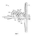
- FIG. 7 is an end view demonstrating a second step of the method for assembling the window frame assembly of FIG. 1 .
- FIG. 8 is an end view demonstrating a third step of the method for assembling the window frame assembly of FIG. 1 .
- FIG. 9 is an end view demonstrating a fourth step of the method for assembling the window frame assembly of FIG. 1 .
- FIG. 10 is an end view of a method for assembling another aspect of the window frame assembly in accordance with another aspect of the present disclosure
- FIG. 11 is a front view of another aspect of the window frame assembly in which the window frame assembly is a single hung window assembly, in accordance with another aspect of the present disclosure.
- FIG. 12 is a perspective view of a sash of the window frame assembly of FIG. 11 .
- FIG. 13 is a perspective view of a fixed window of the window frame assembly of FIG. 11 .
- FIG. 14 is a perspective cross-sectional view of the window frame assembly of FIG. 11 showing the sash closed against a sill of a frame of the fixed window.
- FIG. 15 is a side cross-sectional view of the window frame assembly of FIG. 11 showing the sash closed against the sill of the frame of the fixed window.
- FIG. 16 is a front view of another aspect of the window frame assembly in which the window frame assembly is a horizontal sliding window assembly, in accordance with another aspect of the present disclosure.
- FIG. 17 is a perspective view of a sash of the window frame assembly of FIG. 16 .
- FIG. 18 is a perspective view of a fixed window of the window frame assembly of FIG. 16 .
- FIG. 19 is a perspective cross-sectional view of the window frame assembly of FIG. 16 showing the sash guided by a sill of a frame of the fixed window.
- FIG. 20 is a side cross-sectional view of the window frame assembly of FIG. 16 showing the sash guided by the sill of the frame of the fixed window.
- FIG. 21 shows a side cross-sectional view of another aspect of the setting block and another aspect of the frame in accordance with the present disclosure.
- Ranges can be expressed herein as from “about” one particular value, and/or to “about” another particular value. When such a range is expressed, another aspect includes from the one particular value and/or to the other particular value. Similarly, when values are expressed as approximations, by use of the antecedent “about,” it will be understood that the particular value forms another aspect. It will be further understood that the endpoints of each of the ranges are significant both in relation to the other endpoint, and independently of the other endpoint.
- a material property or dimension measuring about X or substantially X on a particular measurement scale measures within a range between X plus an industry-standard upper tolerance for the specified measurement and X minus an industry-standard lower tolerance for the specified measurement. Because tolerances can vary between different materials, processes and between different models, the tolerance for a particular measurement of a particular component can fall within a range of tolerances.
- the terms “optional” or “optionally” mean that the subsequently described event or circumstance can or cannot occur, and that the description includes instances where said event or circumstance occurs and instances where it does not.
- the window frame assembly can comprise a frame, a setting block, a glazing bead, and a lite. It would be understood by one of skill in the art that the disclosed window frame assembly is described in but a few exemplary aspects among many. No particular terminology or description should be considered limiting on the disclosure or the scope of any claims issuing therefrom.
- FIG. 1 is a detailed cross-sectional view of a window frame assembly 100 comprising a frame 110 , a setting block 140 , a glazing bead 160 , and a lite 180 in accordance with one aspect of the present disclosure.
- the frame 110 can be a fixed frame 112 configured to directly receive the lite 180 .
- the frame 110 can be a stile or a rail of an operable sash, as shown and described in further detail below with respect to FIGS. 11-20 .
- each of the frame 110 , the setting block 140 , and the glazing bead 160 can be extrusions; however, in other aspects, any or all of the frame 110 , the setting block 140 , and the glazing bead 160 can be manufactured through a different process such as casting, for example and without limitation.
- the frame 110 can comprise a flange 114 and a web 116 , and the web 116 can extend outwards from the flange 114 substantially perpendicular to the flange 114 .
- the frame 110 can comprise a plurality of ribs 118 a - f extending outwards from the web 116 .
- the setting block 140 can comprise a plurality of ribs 142 a,b extending outwards from a block body 146 of the setting block 140 .
- the setting block 140 can define a setting block groove 144 extending along the block body 146 between the ribs 142 a,b , and the setting block groove 144 can be configured to engage the ribs 118 a,b , of the frame 110 to secure the setting block 140 to the frame 110 .
- the glazing bead 160 can comprise a bead body 162 and a bead rib 164 , and the bead rib 164 can extend outwards from the bead body 162 .
- the bead body 162 and the bead rib 164 of the glazing bead 160 can substantially define an L-shape; however, in other aspects, the glazing bead 160 can define a different shape, such as a T-shape for example and without limitation.
- the bead rib 164 can be configured to slip underneath a block lip 148 of the setting block 140 , and a bead barb 168 of the bead rib 164 can engage with a setting block barb 150 of the block lip 148 to secure the glazing bead 160 to the setting block 140 .
- the glazing bead 160 can define a bead groove 166 proximate to an intersection between the bead body 162 and the bead rib 164 , and the bead groove 166 can be configured to receive the rib 118 c of the frame 110 to secure the glazing bead 160 to the setting block 140 and the frame 110 .
- the glazing bead 160 and the frame 110 can define a glazing channel 102 , and the glazing channel 102 can receive a first edge 182 of the lite 180 .
- the lite 180 can be an insulating glass unit (“IGU”) 184 comprising a first pane 186 a and a second pane 186 b spaced apart from one another; however, in other aspects, the lite 180 can be a different type of glazing, such as a single pane, laminated glass, or any other suitable type of glazing or infill.
- IGU insulating glass unit
- the glazing bead 160 can comprise a bead weather strip 170 disposed within the glazing channel 102 , and the bead weather strip 170 can be configured to engage and deform against the first pane 186 a to form a seal between the glazing bead 160 and the lite 180 .
- the bead weather strip 170 can comprise a rubber material, and the bead weather strip 170 can define a flange portion 172 and a tubular portion 174 .
- the flange portion 172 can be T-shaped in the present aspect, and the flange portion 172 can be captured by the glazing bead 160 .
- the tubular portion 174 can engage the first pane 186 a , and the tubular portion 174 can be configured to collapse and elastically deform to exert residual pressure against the lite 180 .
- the frame 110 can comprise a frame weather strip 120 disposed within the glazing channel 102 , and the frame weather strip 120 can be configured to engage and form a seal with the second pane 186 b of the lite 180 .
- the frame weather strip 120 can comprise neoprene rubber, and the frame weather strip 120 can be bonded to the flange 114 of the frame 110 , such as with a glue, mastic, epoxy, or any other suitable adhesive.
- the frame weather strip 120 can be treated with an adhesive, and the frame weather strip 120 can also bond to the lite 180 to form a seal between the lite 180 and the frame 110 .
- the setting block 140 can be configured to prevent contact between the first edge 182 of the lite 180 and the web 116 of the frame 110 in order to reduce conduction of heat between the lite 180 and the frame 110 and to prevent stress risers along the first edge 182 of the lite 180 caused by thermal expansion and contraction of the lite 180 .
- the setting block 140 can support the weight of the lite 180 .
- a gap may be defined between the lite 180 and the setting block 140 to allow for thermal expansion of the lite 180 , as shown.
- FIG. 2 is a perspective view of the frame 110 of FIG. 1 .
- the frame weather strip 120 can be covered by a backing strip 220 .
- the backing strip 220 can cover and protect an adhesive coating applied to the frame weather strip 120 . By removing the backing strip 220 , the adhesive coating can be exposed in order to bond the frame weather strip 120 to the lite 180 as shown in FIG. 1 .
- FIG. 3 is a perspective view of the setting block 140 of FIG. 1 .
- the block body 146 can define a first end 310 and a second end 312 disposed opposite from the first end 310 .
- each of the ribs 142 a,b , the setting block barb 150 and the setting block groove 144 can extend from the first end 310 to the second end 312 .
- the block body 146 can also define a first edge 302 and a second edge 304 disposed opposite from the first edge 302 .
- the rib 142 b can be disposed at the first edge 302
- the setting block barb 150 can be disposed at the second edge 304 .
- the block body 146 can also define a frame side 306 and a lite side 308 disposed opposite from the frame side 306 .
- each of the ribs 142 a,b and the setting block barb 150 can extend outwards from the frame side 306 of the block body 146
- the setting block groove 144 can extend along the frame side 306 .
- the lite side 308 can be substantially planar; however, in other aspects, the lite side 308 can define a different shape, such as a grooved shape, a rounded shape, or any other suitable shape, for example and without limitation.
- the rib 142 a can be a block toe rib 342 a
- the rib 142 b can be a block heel rib 342 b
- the block toe rib 342 a can define a lip 346 which extends back towards the first edge 302 to partially enclose a toe pocket portion 348 of the setting block groove 144 .
- the block heel rib 342 b can define a substantially rectangular cross-section; however in other aspects, the block heel rib 342 b can define a lip extending towards the second edge 304 , as shown and further described below with respect to FIG. 10 .
- the block heel rib 342 b can define a different cross-sectional shape, such as L-shaped, triangular, trapezoidal, C-shaped, or any other suitable shape, for example and without limitation.
- FIG. 4 is a perspective view of the glazing bead 160 of FIG. 1 .
- the bead body 162 can define a first end 402 and a second end 404 disposed opposite from the first end 402 .
- the bead rib 164 can extend along the bead body 162 from the first end 402 to the second end 404 .
- the bead body 162 can also define a first edge 410 and a second edge 412 disposed opposite from the first edge 410 .
- the bead rib 164 can be disposed proximate to the second edge 412 , and the bead groove 166 can be defined at the second edge 412 .
- the bead body 162 can further define a first side 406 and a second side 408 .
- the bead rib 164 can extend outwards from the first side 406 of the bead body 162 , and the first side 406 can partially define the glazing channel 102 , as shown in FIG. 1 .
- a pair of ribs 472 a,b can also extend outwards from the first side 406 , and the pair of ribs 472 a,b can define a T-slot 470 configured to receive the flange portion 172 of the bead weather strip 170 .
- the bead weather strip 170 is shown partially slid out of the T-slot 470 towards the second end 404 of the bead body 162 to more clearly shows the details of the ribs 472 a,b and the T-slot 470 .
- FIG. 5 is an end view of the frame 110 of FIG. 1 .
- the flange 114 can define a first edge 502 and a second edge 504 disposed opposite from the first edge 502 .
- the flange 114 can also define a first side 510 and a second side 512 disposed opposite from the first side 510 .
- the web 116 can extend outwards from the first side 510 of the flange 114 , and the frame weather strip 120 can be attached to the first side 510 .
- the flange 114 can also define a pair of lips 514 a,b disposed at the first edge 502 and the second edge 504 , respectively, and the lips 514 a,b can extend outwards from the first side 510 of the flange 114 .
- the web 116 can define a first end 506 and a second end 508 disposed opposite from the first end 506 .
- the first end 506 of the web 116 can be attached to the flange 114 .
- the web 116 can also define a first side 516 and a second side 517 .
- the first side 516 can face the first edge 502 of the flange 114
- the second side 517 can face the second edge 504 of the flange 114 .
- the ribs 118 a - c can extend outwards from the first side 516 of the web 116
- the ribs 118 d - f can extend outwards from the second side 517 of the web 116 .
- the ribs 118 a,d can be positioned proximate to the first end 506 of the web 116 .
- the ribs 118 c,f can be positioned proximate to the second end 508 of the web 116 .
- the rib 118 b can be disposed on the first side 516 between the ribs 118 a,c .
- the rib 118 b can be a frame toe rib 522 a , and in the present aspect, the frame toe rib 522 a can define a lip 524 a which can extend towards the second end 508 of the web 116 .
- the rib 118 a can be a frame heel rib 518 a , and in the present aspect, the frame heel rib 518 a can define a lip 520 a extending towards the first end 506 of the web 116 .
- each of the frame toe rib 522 a and the frame heel rib 518 a can substantially define an L-shape.
- the frame toe rib 522 a and the frame heel rib 518 a can be configured to engage the block toe rib 342 a and the block heel rib 342 b (ribs 342 a,b shown in FIG. 3 ) to secure the setting block 140 (shown in FIG. 3 ) to the frame 110 , as shown and further described below in FIGS. 6 and 7 .
- the rib 118 c can be a bead clip 526 a which can be configured to engage the bead groove 166 (shown in FIG. 1 ) to secure the glazing bead 160 (shown in FIG.
- the bead clip 526 a can define a substantially trapezoidal cross-sectional shape, and the bead clip 526 a can be swept towards the first end 506 of the web 116 to define an acute groove 528 a.
- the frame toe rib 522 a , the frame heel rib 518 a , and the bead clip 526 a can define a frame detail geometry 590 a .
- the frame detail geometry 590 a can be defined by a framing member configured for mounting glazing, such as a stile or rail of a sash or fixed frame, or any other member.
- the ribs 118 d - f can define a variation of the frame detail geometry 590 b .
- the rib 118 f can be a bead clip 526 b which can be substantially similar to the bead clip 526 a , and the bead clip 526 b can define an acute groove 528 b similar to the acute groove 528 a .
- the rib 118 e can be a frame toe rib 522 b which can be similar to the frame toe rib 522 a , and the frame toe rib 522 b can define a lip 524 b which can be substantially similar to the lip 524 a .
- the frame toe rib 522 b can further define a lip 525 extending towards the first end 506 of the web 116 .
- the rib 118 d can be a frame heel rib 518 b which can be similar to the frame heel rib 518 a
- the frame heel rib 518 b can define a lip 520 b which can be substantially similar to the lip 520 a .
- the frame heel rib 518 b can further define a lip 521 extending towards the second end 508 of the web 116 .
- the frame heel rib 518 b and the frame toe rib 522 b can each substantially define a T-shape.
- the frame heel rib 518 b and the frame toe rib 522 b can additionally define a T-slot 570 , similar to the T-slot 470 (shown in FIG. 4 ), and the frame heel rib 518 b and the frame toe rib 522 b can be configured to optionally mount a second setting block 140 (shown in FIG.
- FIG. 6 is an end view demonstrating a first step 600 of a method for assembling the window frame assembly 100 of FIG. 1 .
- the setting block 140 can be angled relative to the first side 516 of the web 116 so that the second edge 304 of the block body 146 is positioned closer to the first side 516 than the first edge 302 of the block body 146 .
- the frame toe rib 522 a can then be inserted into the setting block groove 144 , and the lip 524 a can be inserted into the toe pocket portion 348 of the setting block groove 144 and engaged with the lip 346 of the block toe ridge 342 a as shown.
- FIG. 7 is an end view demonstrating a second step 700 of the method for assembling the window frame assembly 100 of FIG. 1 .
- steps 600 and 700 can be similar to the motion of slipping a shoe onto a human foot wherein the setting block 140 is analogous to the shoe, and the frame toe rib 522 a and frame heel rib 518 a are analogous to the toe and heel of a human foot, respectively.
- the setting block 140 can be secured to the frame 110 .
- the setting block 140 can be sized to snap over the frame heel rib 518 a ; however, in other aspects, such as the aspect shown in FIG. 10 , the block heel rib 342 b can define a lip 1342 (shown in FIG.
- a gap 702 can be defined between the setting block barb 150 of the block lip 148 and the first side 516 of the web 116 .
- FIG. 8 is an end view demonstrating a third step 800 of the method for assembling the window frame assembly 100 of FIG. 1 .
- the bead rib 164 can be slipped over the bead clip 526 a and into the gap 702 (shown in FIG. 7 ) between the setting block barb 150 of the block lip 148 and the first side 516 of the web 116 .
- the bead rib 164 can define a locking ledge 866 which can be swept towards the bead groove 166 , and in the position shown, the locking ledge 866 can rest upon the bead clip 526 a.
- FIG. 9 is an end view demonstrating a fourth step 900 of the method for assembling the window frame assembly 100 of FIG. 1 .
- the bead rib 164 can be further inserted between the block lip 148 and the first side 516 of the web 116 until the bead barb 168 slips past the setting block barb 150 .
- the block lip 148 and the bead rib 164 can elastically deflect so that the bead barb 168 can snap or click past the setting block barb 150 , thereby resisting removal of the glazing bead 160 from the frame 110 and the setting block 140 .
- the second edge 412 of the bead body 162 can be rocked towards the first side 516 of the web 116 so that the bead clip 526 a engages the bead groove 166 and the locking ledge 866 engages the acute groove 528 a .
- Engagement between the bead clip 526 a and the bead groove 166 as well as the locking ledge 866 and the acute groove 528 a can also snap the glazing bead 160 into place, thereby securing the glazing bead 160 to the frame 110 and setting block 140 in a secured position.
- the glazing bead 160 can be released by rocking the first edge 410 of the bead body 162 towards the first edge 502 of the flange 114 , thereby releasing the bead clip 526 a from the bead groove 166 and allowing withdrawal of the bead rib 164 from between the block lip 148 and the web 116 .
- the lite 180 shown in FIG. 1
- compression of the bead weather strip 170 resists this rocking motion, thereby biasing the glazing bead 160 towards the secured position.
- FIG. 10 shows an end view of a method for assembling another aspect of the window frame assembly 100 in accordance with another aspect of the present disclosure.
- the window frame assembly 100 can comprise another aspect of the setting block 140 and another aspect of the frame 110 in accordance with another aspect of the present disclosure.
- the block heel rib 342 b can define the lip 1342 extending towards the block toe rib 342 a .
- the lip 1342 can be configured to engage the lip 520 a of the frame heel rib 518 a , as shown in Step 1 , Step 2 , and Step 3 .
- the block heel rib 342 b can slightly elastically deform as the lip 1342 slips over the lip 520 a , and the lip 1342 can snap between the lip 520 a and the first side 516 of the web 116 to secure the setting block 140 to the frame 110 .
- the glazing bead 160 can snap into engagement with the setting block 140 and the frame 110 with a lite 180 positioned between the glazing bead 160 and the frame 110 .
- the snapping action of the setting block 140 engaging the frame 110 and the glazing bead 160 engaging the frame 110 and the setting block 140 can provide multiple benefits.
- the snapping action provides tactile feedback to an assembler which indicates to the assembler that the components are secured in position.
- it can be unclear to the assembler when the components are properly set, particularly for an inexperienced or new assembler.
- glazing beads can be installed by tapping the glazing beads into place with hammer, such as a rubber mallet.
- the assembler may overstress the glazing bead or the lite by continuing to pound on the glazing bead once it has already been set or by pounding excessively hard on the glazing bead. Overstressing the components of other window frame assemblies can lead to failures during assembly, installation, or service. By providing positive tactile feedback that the setting block 140 and glazing bead 160 are properly set, these failures can be prevented.
- FIG. 11 is a front view of another aspect of the window frame assembly 100 in which the window frame assembly 100 is a single hung window assembly, in accordance with another aspect of the present disclosure.
- the window frame assembly 100 can comprise a fixed window 1100 a which can be fixed in place and a sash 1100 b which can be operably moved upwards and downwards in a vertical direction.
- the frame 110 a of the fixed window 1100 a can be a fixed frame
- the frame 110 b of the sash 1100 b can be a sash frame.
- FIG. 11 demonstrates one common configuration for the positioning of the setting blocks 140 a - p around each respective lite 180 a,b .
- two setting blocks 140 can be evenly distributed along each side of each respective lite 180 a,b ; however, this distribution is not limiting.
- a very large lite or a very heavy lite can have more than two setting blocks 140 positioned along each side.
- a single setting block 140 can be positioned along each side of each respective lite 180 a,b .
- each setting block 140 can be extended in length.
- a single extended setting block 140 can extend over half a width of a side of the respective lite 180 a,b , for example and without limitation.
- FIG. 12 is a perspective view of the sash 1100 b of FIG. 11
- FIG. 13 is a perspective view of the fixed window 1100 a of FIG. 11 .
- FIG. 14 is a perspective cross-sectional view of the window frame assembly 100 of FIG. 11 showing the sash 1100 b closed against a sill 1400 of the frame 120 a of the fixed window 1100 a .
- FIG. 15 is a side cross-sectional view of the window frame assembly 100 of FIG. 11 showing the sash 1100 b closed against the sill 1400 of the frame 120 a of the fixed window 1100 a.
- FIG. 16 is a front view of another aspect of the window frame assembly 100 in which the window frame assembly 100 is a horizontal sliding window assembly, in accordance with another aspect of the present disclosure.
- the window frame assembly 100 can comprise a fixed window 1600 a which can be fixed in place and a sash 1600 b which can be operably moved side to side in a horizontal direction.
- the frame 110 a of the fixed window 1600 a can be a fixed frame
- the frame 110 b of the sash 1600 b can be a sash frame.
- the sash 1600 b can ride within the frame 120 a of the fixed window 1600 a . Similar to FIG. 11 , FIG.
- 16 demonstrates one common configuration for the positioning of the setting blocks 140 a - p around each respective lite 180 a,b .
- two setting blocks 140 can be evenly distributed along each side of each respective lite 180 a,b ; however, this distribution is not limiting.
- a very large lite or a very heavy lite can have more than two setting blocks 140 positioned along each side.
- a single setting block 140 can be positioned along each side of each respective lite 180 a,b .
- each setting block 140 can be extended in length.
- a single extended setting block 140 can extend over half a width of a side of the respective lite 180 a,b , for example and without limitation.
- FIG. 17 is a perspective view of the sash 1600 b of FIG. 16
- FIG. 18 is a perspective view of the fixed window 1600 a of FIG. 16 .
- FIG. 19 is a perspective cross-sectional view of the window frame assembly 100 of FIG. 16 showing the sash 1600 b guided by a sill 1900 of the frame 120 a of the fixed window 1600 a .
- FIG. 20 is a side cross-sectional view of the window frame assembly 100 of FIG. 16 showing the sash 1600 b guided by the sill 1900 of the frame 120 a of the fixed window 1600 a.
- FIG. 21 is a side cross-sectional view of another aspect of the setting block 140 and another aspect of the frame 110 in accordance with the present disclosure.
- the setting block 140 , the block heel rib 342 b can comprise a heel barb 2142 .
- the heel barb 2142 can define at least one spur 2146 extending outwards and away from the block heel rib 342 b .
- the frame 110 can define a kerf 2110 configured to receive the heel barb 2142 .
- the kerf 2110 can define at least one groove 2112 within the kerf 2110 which can be sized and shaped to receive the plurality of spurs 2146 of the heel barb 2142 to secure the block heel rib 342 b to the frame 110 .
- the number of spurs 2146 and grooves 2112 should not be viewed as limiting.
- conditional language such as, among others, “can,” “could,” “might,” or “may,” unless specifically stated otherwise, or otherwise understood within the context as used, is generally intended to convey that certain embodiments include, while other embodiments do not include, certain features, elements and/or steps. Thus, such conditional language is not generally intended to imply that features, elements and/or steps are in any way required for one or more particular embodiments or that one or more particular embodiments necessarily include logic for deciding, with or without user input or prompting, whether these features, elements and/or steps are included or are to be performed in any particular embodiment.
Landscapes
- Engineering & Computer Science (AREA)
- Civil Engineering (AREA)
- Structural Engineering (AREA)
- Securing Of Glass Panes Or The Like (AREA)
Abstract
Description
Claims (20)
Priority Applications (1)
| Application Number | Priority Date | Filing Date | Title |
|---|---|---|---|
| US16/035,952 US10415302B2 (en) | 2018-01-08 | 2018-07-16 | Window setting block |
Applications Claiming Priority (2)
| Application Number | Priority Date | Filing Date | Title |
|---|---|---|---|
| US201862614684P | 2018-01-08 | 2018-01-08 | |
| US16/035,952 US10415302B2 (en) | 2018-01-08 | 2018-07-16 | Window setting block |
Publications (2)
| Publication Number | Publication Date |
|---|---|
| US20190211612A1 US20190211612A1 (en) | 2019-07-11 |
| US10415302B2 true US10415302B2 (en) | 2019-09-17 |
Family
ID=67140124
Family Applications (1)
| Application Number | Title | Priority Date | Filing Date |
|---|---|---|---|
| US16/035,952 Active US10415302B2 (en) | 2018-01-08 | 2018-07-16 | Window setting block |
Country Status (1)
| Country | Link |
|---|---|
| US (1) | US10415302B2 (en) |
Cited By (4)
| Publication number | Priority date | Publication date | Assignee | Title |
|---|---|---|---|---|
| US20220065026A1 (en) * | 2019-01-14 | 2022-03-03 | Vkr Holding A/S | Vig frame solution with flexible portion |
| USD952906S1 (en) | 2019-02-07 | 2022-05-24 | Wws Acquisition Llc | Muntin bar assembly |
| US20230151678A1 (en) * | 2021-11-12 | 2023-05-18 | Riot Glass LLC | Security panel mounting system |
| US11739585B1 (en) * | 2019-02-07 | 2023-08-29 | WWS Acquisition, LLC | Simulated steel fenestration system |
Families Citing this family (5)
| Publication number | Priority date | Publication date | Assignee | Title |
|---|---|---|---|---|
| US11414886B2 (en) * | 2018-01-08 | 2022-08-16 | PGT Innovations, Inc | Window security device |
| CN111927263B (en) * | 2020-06-06 | 2022-06-24 | 青岛万和装饰门窗工程有限公司 | Glass cushion block assembly and mounting method thereof |
| CN111734262A (en) * | 2020-07-28 | 2020-10-02 | 江西广迪智能钢艺集团有限公司 | A quick press buckle structure |
| CN112277582B (en) * | 2020-10-27 | 2024-03-08 | 福建福耀汽车饰件有限公司 | A quick-detachable window frame structure |
| GB2598976B (en) * | 2021-03-10 | 2023-03-01 | Eurocell Profiles Ltd | Glazing bead |
Citations (27)
| Publication number | Priority date | Publication date | Assignee | Title |
|---|---|---|---|---|
| GB448743A (en) | 1935-08-30 | 1936-06-15 | Pittsburg Plate Glass Company | Improvements in or relating to store front constructions |
| US2612663A (en) * | 1947-02-06 | 1952-10-07 | Libbey Owens Ford Glass Co | Glass setting device |
| US3155205A (en) | 1962-04-09 | 1964-11-03 | E K Geyser Company | Metal window sash |
| US3238685A (en) | 1963-10-18 | 1966-03-08 | Pemko Mfg Company | Window glazing and retaining means |
| US3242627A (en) | 1962-12-14 | 1966-03-29 | James L Fountain | Glazing frame assembly |
| GB1271522A (en) | 1968-09-11 | 1972-04-19 | Miles Redfern Ltd | Glazing and the like |
| US3703063A (en) * | 1969-04-22 | 1972-11-21 | Dynamit Nobel Ag | Profile member for windows, doors, facades, or the like |
| US3774363A (en) * | 1971-05-10 | 1973-11-27 | Creators Ltd | Glazing window or windscreen openings, particularly in vehicle bodies |
| US3846948A (en) | 1969-06-09 | 1974-11-12 | Standard Products Co | Glazing system |
| US4040219A (en) * | 1974-11-02 | 1977-08-09 | Dynamit Nobel Aktiengesellschaft | Profile arrangement for window frames or doorframes |
| US4187657A (en) * | 1978-07-03 | 1980-02-12 | Swiss Aluminium Ltd. | Thermal windows |
| US4314424A (en) * | 1979-12-26 | 1982-02-09 | Gordon Stanley J | Thermal window construction |
| US4447985A (en) * | 1982-06-16 | 1984-05-15 | Wausau Metals Corporation | Window structure |
| US4614062A (en) * | 1983-11-30 | 1986-09-30 | Swiss Aluminium Ltd. | Metal frame assembly for windows or doors |
| US4628648A (en) * | 1984-12-19 | 1986-12-16 | American Welding & Manufacturing Co. | Framing structure |
| US4852312A (en) * | 1988-12-23 | 1989-08-01 | Plastmo Ltd. | Window frame assembly |
| US5044121A (en) * | 1990-02-06 | 1991-09-03 | Plastmo Ltd. | Improved window and door structure |
| US5410846A (en) * | 1993-08-20 | 1995-05-02 | Frambach; Harry | Window structure |
| GB2292170A (en) | 1994-07-08 | 1996-02-14 | P B Systems Ltd | Glazing bead |
| US5950379A (en) | 1995-01-09 | 1999-09-14 | Florida Extruders International, Inc. | Window frame with angled glazing legs |
| US6679013B2 (en) | 2001-11-15 | 2004-01-20 | Sashlite, Llc | Window assembly with hinged components |
| US20040231255A1 (en) | 2003-05-19 | 2004-11-25 | Silver Line Building Products Corp. | Method of glazing insulated sash frame |
| EP2450517A1 (en) | 2010-11-03 | 2012-05-09 | Cuhadaroglu Metal Sanayi Ve Pazarlama Anonim Sirketi | Door and window system consisting of thermally-insulated aluminium profiles with concealed glazing bead, gasket of which is on thereof |
| US8484902B1 (en) * | 2012-10-17 | 2013-07-16 | Hope's Window, Inc. | Window assembly having a thermal break liner |
| US8621793B2 (en) | 2003-07-30 | 2014-01-07 | City Glass & Glazing (P) Ltd. | Glazing system |
| EP3246505A1 (en) * | 2016-05-17 | 2017-11-22 | SCHÜCO International KG | Composite profile for doors, window or façade elements |
| US20180163458A1 (en) * | 2016-12-12 | 2018-06-14 | Gregory A. Header | High Performance Fenestration System |
-
2018
- 2018-07-16 US US16/035,952 patent/US10415302B2/en active Active
Patent Citations (27)
| Publication number | Priority date | Publication date | Assignee | Title |
|---|---|---|---|---|
| GB448743A (en) | 1935-08-30 | 1936-06-15 | Pittsburg Plate Glass Company | Improvements in or relating to store front constructions |
| US2612663A (en) * | 1947-02-06 | 1952-10-07 | Libbey Owens Ford Glass Co | Glass setting device |
| US3155205A (en) | 1962-04-09 | 1964-11-03 | E K Geyser Company | Metal window sash |
| US3242627A (en) | 1962-12-14 | 1966-03-29 | James L Fountain | Glazing frame assembly |
| US3238685A (en) | 1963-10-18 | 1966-03-08 | Pemko Mfg Company | Window glazing and retaining means |
| GB1271522A (en) | 1968-09-11 | 1972-04-19 | Miles Redfern Ltd | Glazing and the like |
| US3703063A (en) * | 1969-04-22 | 1972-11-21 | Dynamit Nobel Ag | Profile member for windows, doors, facades, or the like |
| US3846948A (en) | 1969-06-09 | 1974-11-12 | Standard Products Co | Glazing system |
| US3774363A (en) * | 1971-05-10 | 1973-11-27 | Creators Ltd | Glazing window or windscreen openings, particularly in vehicle bodies |
| US4040219A (en) * | 1974-11-02 | 1977-08-09 | Dynamit Nobel Aktiengesellschaft | Profile arrangement for window frames or doorframes |
| US4187657A (en) * | 1978-07-03 | 1980-02-12 | Swiss Aluminium Ltd. | Thermal windows |
| US4314424A (en) * | 1979-12-26 | 1982-02-09 | Gordon Stanley J | Thermal window construction |
| US4447985A (en) * | 1982-06-16 | 1984-05-15 | Wausau Metals Corporation | Window structure |
| US4614062A (en) * | 1983-11-30 | 1986-09-30 | Swiss Aluminium Ltd. | Metal frame assembly for windows or doors |
| US4628648A (en) * | 1984-12-19 | 1986-12-16 | American Welding & Manufacturing Co. | Framing structure |
| US4852312A (en) * | 1988-12-23 | 1989-08-01 | Plastmo Ltd. | Window frame assembly |
| US5044121A (en) * | 1990-02-06 | 1991-09-03 | Plastmo Ltd. | Improved window and door structure |
| US5410846A (en) * | 1993-08-20 | 1995-05-02 | Frambach; Harry | Window structure |
| GB2292170A (en) | 1994-07-08 | 1996-02-14 | P B Systems Ltd | Glazing bead |
| US5950379A (en) | 1995-01-09 | 1999-09-14 | Florida Extruders International, Inc. | Window frame with angled glazing legs |
| US6679013B2 (en) | 2001-11-15 | 2004-01-20 | Sashlite, Llc | Window assembly with hinged components |
| US20040231255A1 (en) | 2003-05-19 | 2004-11-25 | Silver Line Building Products Corp. | Method of glazing insulated sash frame |
| US8621793B2 (en) | 2003-07-30 | 2014-01-07 | City Glass & Glazing (P) Ltd. | Glazing system |
| EP2450517A1 (en) | 2010-11-03 | 2012-05-09 | Cuhadaroglu Metal Sanayi Ve Pazarlama Anonim Sirketi | Door and window system consisting of thermally-insulated aluminium profiles with concealed glazing bead, gasket of which is on thereof |
| US8484902B1 (en) * | 2012-10-17 | 2013-07-16 | Hope's Window, Inc. | Window assembly having a thermal break liner |
| EP3246505A1 (en) * | 2016-05-17 | 2017-11-22 | SCHÜCO International KG | Composite profile for doors, window or façade elements |
| US20180163458A1 (en) * | 2016-12-12 | 2018-06-14 | Gregory A. Header | High Performance Fenestration System |
Non-Patent Citations (1)
| Title |
|---|
| Tubelite Inc.; Article entitled: "Glass Stops", located at <https://web.archive.org/web/20141017115438/http:/www.tubeliteinc.com:80/glass-stops/>, publicly available as early as Oct. 17, 2014, 1 pgs. |
Cited By (19)
| Publication number | Priority date | Publication date | Assignee | Title |
|---|---|---|---|---|
| US12110736B2 (en) * | 2019-01-14 | 2024-10-08 | Vkr Holding A/S | Frame providing restriction of thermal deflection of a VIG unit edge |
| US20240368937A1 (en) * | 2019-01-14 | 2024-11-07 | Vkr Holding A/S | Frame providing restriction of thermal deflection of a vig unit edge |
| US20220081959A1 (en) * | 2019-01-14 | 2022-03-17 | Vkr Holding A/S | Frame solution for laminated vig unit |
| US20240044201A1 (en) * | 2019-01-14 | 2024-02-08 | Vkr Holding A/S | Vacuum insulated glass unit frame solution |
| US20220127899A1 (en) * | 2019-01-14 | 2022-04-28 | Vkr Holding A/S | Frame assembly comprising a vacuum insulated glass unit fixed to a frame by means of a structural adhesive |
| US12320184B2 (en) * | 2019-01-14 | 2025-06-03 | Vkr Holding A/S | Frame solution for laminated VIG unit |
| US12270245B2 (en) * | 2019-01-14 | 2025-04-08 | Vkr Holding A/S | Frame assembly comprising a vacuum insulated glass unit fixed to a frame by means of a structural adhesive |
| US12215540B2 (en) * | 2019-01-14 | 2025-02-04 | Vkr Holding A/S | VIG frame solution with flexible portion |
| US20220081961A1 (en) * | 2019-01-14 | 2022-03-17 | Vkr Holding A/S | Frame providing restriction of thermal deflection of a vig unit edge |
| US11959331B2 (en) * | 2019-01-14 | 2024-04-16 | Vkr Holding A/S | Building aperture cover with VIG unit connected to fixation profile |
| US20220081958A1 (en) * | 2019-01-14 | 2022-03-17 | Vkr Holding A/S | Building aperture cover with vig unit connected to fixation profile |
| US12168906B2 (en) * | 2019-01-14 | 2024-12-17 | Vkr Holding A/S | Vacuum insulated glass unit frame solution |
| US20220065026A1 (en) * | 2019-01-14 | 2022-03-03 | Vkr Holding A/S | Vig frame solution with flexible portion |
| US11739585B1 (en) * | 2019-02-07 | 2023-08-29 | WWS Acquisition, LLC | Simulated steel fenestration system |
| US11976509B1 (en) | 2019-02-07 | 2024-05-07 | Pgt Innovations, Llc | Simulated steel fenestration system |
| USD953577S1 (en) | 2019-02-07 | 2022-05-31 | Wws Acquisition Llc | Muntin bar assembly |
| USD952906S1 (en) | 2019-02-07 | 2022-05-24 | Wws Acquisition Llc | Muntin bar assembly |
| US20230151678A1 (en) * | 2021-11-12 | 2023-05-18 | Riot Glass LLC | Security panel mounting system |
| US12467312B2 (en) * | 2021-11-12 | 2025-11-11 | Riot Glass LLC | Security panel mounting system |
Also Published As
| Publication number | Publication date |
|---|---|
| US20190211612A1 (en) | 2019-07-11 |
Similar Documents
| Publication | Publication Date | Title |
|---|---|---|
| US10415302B2 (en) | Window setting block | |
| US3016993A (en) | Building framing unit | |
| EP0130438B1 (en) | Structural spacer glazing | |
| US20140345215A1 (en) | Thermal break for curtain wall | |
| US2781561A (en) | Glazing construction | |
| US20210140214A1 (en) | Spring-loaded sash guide | |
| US20140053479A1 (en) | Sash binder | |
| KR101421965B1 (en) | Terracotta panel fixing device | |
| US3946524A (en) | Blind frame and sash constructions for sash windows, sliding doors, and the like | |
| US4766709A (en) | Double-paned window securement | |
| WO2018150167A1 (en) | Rail installation method and rail system | |
| WO2019072935A2 (en) | Frame sealing system, curtain walling system and method of mounting a curtain wall | |
| EP0648310B1 (en) | Composite section | |
| CN206158498U (en) | Steel window and door system | |
| US3238685A (en) | Window glazing and retaining means | |
| US20200369139A1 (en) | Outer waist seal assembly for a vehicle | |
| KR20160006397A (en) | Finishing material for remodeling window | |
| JP5323764B2 (en) | Refurbished windows | |
| CA1065683A (en) | Retaining system for architectural glazing strip | |
| US2983002A (en) | Windows | |
| US2451654A (en) | Window structure | |
| US20240247536A1 (en) | Simulated steel fenestration system | |
| EP2286050B1 (en) | Mounting means for glass panes | |
| CN106255795B (en) | Composite profile for door, window or facade elements | |
| US10329778B2 (en) | Pressure plate with integrated pressure indicator |
Legal Events
| Date | Code | Title | Description |
|---|---|---|---|
| FEPP | Fee payment procedure |
Free format text: ENTITY STATUS SET TO UNDISCOUNTED (ORIGINAL EVENT CODE: BIG.); ENTITY STATUS OF PATENT OWNER: LARGE ENTITY |
|
| AS | Assignment |
Owner name: PGT INNOVATIONS, INC., FLORIDA Free format text: ASSIGNMENT OF ASSIGNORS INTEREST;ASSIGNORS:VANDER BENT, KENNETH JOHN, JR;NAU, MICHAEL DIETMAR;CHEN, HONG;SIGNING DATES FROM 20180711 TO 20180713;REEL/FRAME:046373/0201 |
|
| STPP | Information on status: patent application and granting procedure in general |
Free format text: PUBLICATIONS -- ISSUE FEE PAYMENT RECEIVED |
|
| STPP | Information on status: patent application and granting procedure in general |
Free format text: PUBLICATIONS -- ISSUE FEE PAYMENT VERIFIED |
|
| STCF | Information on status: patent grant |
Free format text: PATENTED CASE |
|
| AS | Assignment |
Owner name: SUNTRUST BANK, GEORGIA Free format text: SECURITY AGREEMENT;ASSIGNOR:PGT INNOVATIONS, INC.;REEL/FRAME:050897/0075 Effective date: 20191031 |
|
| MAFP | Maintenance fee payment |
Free format text: PAYMENT OF MAINTENANCE FEE, 4TH YEAR, LARGE ENTITY (ORIGINAL EVENT CODE: M1551); ENTITY STATUS OF PATENT OWNER: LARGE ENTITY Year of fee payment: 4 |
|
| AS | Assignment |
Owner name: PGT INNOVATIONS, LLC, PENNSYLVANIA Free format text: ENTITY CONVERSION AND CHANGE OF NAME;ASSIGNOR:PGT INNOVATIONS, INC.;REEL/FRAME:066946/0139 Effective date: 20240328 |
|
| AS | Assignment |
Owner name: U.S. BANK NATIONAL ASSOCIATION, AS COLLATERAL AGENT, MINNESOTA Free format text: PATENT SECURITY AGREEMENT (NOTES);ASSIGNORS:PGT INNOVATIONS, LLC;WESTERN WINDOW HOLDING, LLC;MDM UTAH, LLC;AND OTHERS;REEL/FRAME:066953/0070 Effective date: 20240328 |
|
| AS | Assignment |
Owner name: ROYAL BANK OF CANADA, AS COLLATERAL AGENT, CANADA Free format text: PATENT SECURITY AGREEMENT (ABL);ASSIGNORS:CGI WINDOWS AND DOORS, LLC;MDM UTAH, LLC;PGT INDUSTRIES, LLC;AND OTHERS;REEL/FRAME:066974/0256 Effective date: 20240328 Owner name: ROYAL BANK OF CANADA, AS COLLATERAL AGENT, CANADA Free format text: PATENT SECURITY AGREEMENT (TERM);ASSIGNORS:CGI WINDOWS AND DOORS, LLC;MDM UTAH, LLC;PGT INDUSTRIES, LLC;AND OTHERS;REEL/FRAME:066975/0062 Effective date: 20240328 |
|
| AS | Assignment |
Owner name: PGT INNOVATIONS, INC., FLORIDA Free format text: RELEASE (REEL 050897 / FRAME 0075);ASSIGNOR:TRUIST BANK (AS SUCCESSOR BY MERGER TO SUNTRUST BANK);REEL/FRAME:067000/0709 Effective date: 20240328 |