US10404283B2 - Method and associated decoding circuit for decoding an error correction code - Google Patents
Method and associated decoding circuit for decoding an error correction code Download PDFInfo
- Publication number
- US10404283B2 US10404283B2 US15/259,065 US201615259065A US10404283B2 US 10404283 B2 US10404283 B2 US 10404283B2 US 201615259065 A US201615259065 A US 201615259065A US 10404283 B2 US10404283 B2 US 10404283B2
- Authority
- US
- United States
- Prior art keywords
- error
- correction code
- result
- error correction
- decoding
- Prior art date
- Legal status (The legal status is an assumption and is not a legal conclusion. Google has not performed a legal analysis and makes no representation as to the accuracy of the status listed.)
- Active
Links
Images


Classifications
-
- H—ELECTRICITY
- H03—ELECTRONIC CIRCUITRY
- H03M—CODING; DECODING; CODE CONVERSION IN GENERAL
- H03M13/00—Coding, decoding or code conversion, for error detection or error correction; Coding theory basic assumptions; Coding bounds; Error probability evaluation methods; Channel models; Simulation or testing of codes
- H03M13/03—Error detection or forward error correction by redundancy in data representation, i.e. code words containing more digits than the source words
- H03M13/05—Error detection or forward error correction by redundancy in data representation, i.e. code words containing more digits than the source words using block codes, i.e. a predetermined number of check bits joined to a predetermined number of information bits
- H03M13/13—Linear codes
- H03M13/15—Cyclic codes, i.e. cyclic shifts of codewords produce other codewords, e.g. codes defined by a generator polynomial, Bose-Chaudhuri-Hocquenghem [BCH] codes
- H03M13/151—Cyclic codes, i.e. cyclic shifts of codewords produce other codewords, e.g. codes defined by a generator polynomial, Bose-Chaudhuri-Hocquenghem [BCH] codes using error location or error correction polynomials
- H03M13/1575—Direct decoding, e.g. by a direct determination of the error locator polynomial from syndromes and subsequent analysis or by matrix operations involving syndromes, e.g. for codes with a small minimum Hamming distance
-
- H—ELECTRICITY
- H03—ELECTRONIC CIRCUITRY
- H03M—CODING; DECODING; CODE CONVERSION IN GENERAL
- H03M13/00—Coding, decoding or code conversion, for error detection or error correction; Coding theory basic assumptions; Coding bounds; Error probability evaluation methods; Channel models; Simulation or testing of codes
- H03M13/03—Error detection or forward error correction by redundancy in data representation, i.e. code words containing more digits than the source words
- H03M13/05—Error detection or forward error correction by redundancy in data representation, i.e. code words containing more digits than the source words using block codes, i.e. a predetermined number of check bits joined to a predetermined number of information bits
- H03M13/13—Linear codes
- H03M13/15—Cyclic codes, i.e. cyclic shifts of codewords produce other codewords, e.g. codes defined by a generator polynomial, Bose-Chaudhuri-Hocquenghem [BCH] codes
- H03M13/151—Cyclic codes, i.e. cyclic shifts of codewords produce other codewords, e.g. codes defined by a generator polynomial, Bose-Chaudhuri-Hocquenghem [BCH] codes using error location or error correction polynomials
- H03M13/1545—Determination of error locations, e.g. Chien search or other methods or arrangements for the determination of the roots of the error locator polynomial
-
- H—ELECTRICITY
- H04—ELECTRIC COMMUNICATION TECHNIQUE
- H04L—TRANSMISSION OF DIGITAL INFORMATION, e.g. TELEGRAPHIC COMMUNICATION
- H04L1/00—Arrangements for detecting or preventing errors in the information received
- H04L1/004—Arrangements for detecting or preventing errors in the information received by using forward error control
- H04L1/0056—Systems characterized by the type of code used
- H04L1/0057—Block codes
-
- H—ELECTRICITY
- H03—ELECTRONIC CIRCUITRY
- H03M—CODING; DECODING; CODE CONVERSION IN GENERAL
- H03M13/00—Coding, decoding or code conversion, for error detection or error correction; Coding theory basic assumptions; Coding bounds; Error probability evaluation methods; Channel models; Simulation or testing of codes
- H03M13/03—Error detection or forward error correction by redundancy in data representation, i.e. code words containing more digits than the source words
- H03M13/05—Error detection or forward error correction by redundancy in data representation, i.e. code words containing more digits than the source words using block codes, i.e. a predetermined number of check bits joined to a predetermined number of information bits
- H03M13/13—Linear codes
- H03M13/15—Cyclic codes, i.e. cyclic shifts of codewords produce other codewords, e.g. codes defined by a generator polynomial, Bose-Chaudhuri-Hocquenghem [BCH] codes
- H03M13/151—Cyclic codes, i.e. cyclic shifts of codewords produce other codewords, e.g. codes defined by a generator polynomial, Bose-Chaudhuri-Hocquenghem [BCH] codes using error location or error correction polynomials
- H03M13/1525—Determination and particular use of error location polynomials
-
- H—ELECTRICITY
- H03—ELECTRONIC CIRCUITRY
- H03M—CODING; DECODING; CODE CONVERSION IN GENERAL
- H03M13/00—Coding, decoding or code conversion, for error detection or error correction; Coding theory basic assumptions; Coding bounds; Error probability evaluation methods; Channel models; Simulation or testing of codes
- H03M13/03—Error detection or forward error correction by redundancy in data representation, i.e. code words containing more digits than the source words
- H03M13/05—Error detection or forward error correction by redundancy in data representation, i.e. code words containing more digits than the source words using block codes, i.e. a predetermined number of check bits joined to a predetermined number of information bits
- H03M13/13—Linear codes
- H03M13/15—Cyclic codes, i.e. cyclic shifts of codewords produce other codewords, e.g. codes defined by a generator polynomial, Bose-Chaudhuri-Hocquenghem [BCH] codes
- H03M13/159—Remainder calculation, e.g. for encoding and syndrome calculation
-
- H—ELECTRICITY
- H03—ELECTRONIC CIRCUITRY
- H03M—CODING; DECODING; CODE CONVERSION IN GENERAL
- H03M13/00—Coding, decoding or code conversion, for error detection or error correction; Coding theory basic assumptions; Coding bounds; Error probability evaluation methods; Channel models; Simulation or testing of codes
- H03M13/37—Decoding methods or techniques, not specific to the particular type of coding provided for in groups H03M13/03 - H03M13/35
- H03M13/3738—Decoding methods or techniques, not specific to the particular type of coding provided for in groups H03M13/03 - H03M13/35 with judging correct decoding
-
- H—ELECTRICITY
- H03—ELECTRONIC CIRCUITRY
- H03M—CODING; DECODING; CODE CONVERSION IN GENERAL
- H03M13/00—Coding, decoding or code conversion, for error detection or error correction; Coding theory basic assumptions; Coding bounds; Error probability evaluation methods; Channel models; Simulation or testing of codes
- H03M13/37—Decoding methods or techniques, not specific to the particular type of coding provided for in groups H03M13/03 - H03M13/35
- H03M13/39—Sequence estimation, i.e. using statistical methods for the reconstruction of the original codes
-
- H—ELECTRICITY
- H03—ELECTRONIC CIRCUITRY
- H03M—CODING; DECODING; CODE CONVERSION IN GENERAL
- H03M13/00—Coding, decoding or code conversion, for error detection or error correction; Coding theory basic assumptions; Coding bounds; Error probability evaluation methods; Channel models; Simulation or testing of codes
- H03M13/65—Purpose and implementation aspects
- H03M13/6502—Reduction of hardware complexity or efficient processing
- H03M13/6505—Memory efficient implementations
-
- H—ELECTRICITY
- H04—ELECTRIC COMMUNICATION TECHNIQUE
- H04L—TRANSMISSION OF DIGITAL INFORMATION, e.g. TELEGRAPHIC COMMUNICATION
- H04L1/00—Arrangements for detecting or preventing errors in the information received
- H04L1/004—Arrangements for detecting or preventing errors in the information received by using forward error control
- H04L1/0056—Systems characterized by the type of code used
- H04L1/0061—Error detection codes
Definitions
- An objective of the present invention is to provide a method and an associated decoding circuit for decoding an error correction code, which can improve the efficiency of error correction.
- Another objective of the present invention is to provide a method and an associated decoding circuit for decoding an error correction code, which can reduce the power consumption of a memory controller performing error correction.
- At least one preferred embodiment of the present invention provides a method for decoding an error correction code.
- the method comprises: calculating a set of error syndromes of the error correction code, wherein the error correction code is a t-error correcting code and has capability of correcting t errors, and a number s of the set of error syndromes is smaller than t; sequentially determining a set of coefficients within a plurality of coefficients of an error locator polynomial of the error correction code according to at least one portion of error syndromes within the set of error syndromes, for building a roughly-estimated error locator polynomial, wherein the number of the plurality of coefficients is equal to t, and the number of the set of coefficients is equal to s; performing a Chien search to determine a plurality of roots of the roughly-estimated error locator polynomial; correcting the error correction code according to the roughly-estimated error locator polynomial in order to generate an correction result of the error correction code; and performing at least one
- the present invention also provides a storage device which comprises the aforementioned decoding circuit.
- the present invention also provides a controller of an electronic device, wherein the controller comprises the aforementioned decoding circuit.
- FIG. 2 is a work flowchart illustrating a method for decoding an error correction code according to an embodiment of the present invention.
- FIG. 4 is a work flow of the method shown in FIG. 2 according to another embodiment of the present invention.
- FIG. 5 is a diagram illustrating a storage device comprising the decoding circuit shown in FIG. 1 according to an embodiment of the present invention.
- FIG. 1 is a diagram illustrating a decoding circuit 100 for decoding an error correction code according to an embodiment of the present invention.
- the error correction code may comprise a set of message bits and a set of parity bits; however, this is merely for illustrative purposes, and not meant to be a limitation of the present invention.
- the decoding circuit 100 may comprise a control module 105 , an error syndrome calculation module 110 , an error locator polynomial determining module 120 , a Chien search module 130 , an error correction module 140 , and a checking module 150 , wherein the error syndrome calculation module 110 may comprise a plurality of error syndrome calculation units, such as the t error syndrome calculation units 110 - 1 , 110 - 2 , . . . , and 110 - t .
- the control module 105 may be arranged to control operations of the decoding circuit 100 . Specifically, the control module 105 may selectively control a number s of enabled error syndrome calculation units 110 - 1 , 110 - 2 , . . .
- control module 105 may selectively control the times s of the error locator polynomial determining module 120 executing the error correction code in a corresponding work flow, wherein the error locator polynomial determining module 120 performs loop calculation upon the error correction code for s times in the corresponding work flow.
- the control module 105 may selectively turn on at least one portion (e.g. part or all) of the error syndrome calculation units in the error syndrome calculation module 110 , and may correspondingly control execution times of the error locator polynomial determining module 120 .
- the control module 105 may selectively turn on the error syndrome calculation units 110 - 1 , 110 - 2 , . . . , and 110 - s , wherein the number s of the error syndrome calculation units 110 - 1 , 110 - 2 , . . . , and 110 - s may be less than the number t of the error syndrome calculation units 110 - 1 , 110 - 2 , . . .
- the control module 105 may correspondingly control execution times of the error locator polynomial determining module 120 , rather than allowing the error locator polynomial determining module 120 to continuously execute the codeword until the maximum times t for one single codeword is achieved.
- the error locator polynomial determining module 120 may process a specific message (e.g. a specific codeword) ahead of schedule, and then immediately process a next message (e.g. a next codeword).
- the decoding circuit 100 may save time and reduce power consumptions. In addition, the overall efficiency of the electronic device having the decoding circuit 100 can be improved.
- the decoding circuit 100 may perform decoding again when taking some decoding errors into consideration. More particularly, the decoding circuit 100 may temporarily set the aforementioned number s to be equal to the aforementioned number t, in order to obtain a correct decoding result. Since errors are unlikely to occur in normal situations, as long as the control parameters of the error correction code are properly designed, the overall decoding efficiency of the decoding circuit 100 for all data may be improved without introducing side effects. Although performing the decoding operation again will inevitably waste time, the improved overall efficiency of the electronic device having the decoding circuit 100 may compensate for the sacrifice.
- the error correction code may be a Bose, Ray-Chaudhuri, and Hocquenghem (BCH) code. According to some embodiments of the present invention, however, the error correction code may be the Reed-Solomon (RS) code.
- RS Reed-Solomon
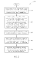
- FIG. 2 is a work flowchart illustrating a method for decoding an error correction code according to an embodiment of the present invention.
- the error correction code may comprise a set of message bits and a set of parity bits.
- the method show in FIG. 2 may be applied to the decoding circuit 100 shown in FIG. 1 .
- the method 200 is described as follows.
- the error syndrome calculation module 110 calculates a set of error syndromes of the error correction code, such as s error syndromes, wherein the error correction code is a t-error correction code and has capability of correcting t errors, and s is smaller than t. More particularly, the error syndrome calculation units 110 - 1 , 110 - 2 , . . . , and 110 - s in the error syndrome calculation module 110 may calculate the s error syndromes, respectively.
- the error locator polynomial determining module 120 refers to at least one portion (e.g. part or all) of error syndromes within the set of error syndromes, to sequentially determine a set of coefficients ⁇ 1 , ⁇ 2 , . . . , and ⁇ s within a plurality of coefficients ⁇ 1 , ⁇ 2 , . . . , and ⁇ t of an error locator polynomial (e.g. a polynomial ⁇ (x)) of the error correction code, for building a roughly-estimated error locator polynomial, wherein the number of the plurality of coefficients ⁇ 1 , ⁇ 2 , . . .
- an error locator polynomial e.g. a polynomial ⁇ (x)
- the calculation order of the set of coefficients ⁇ 1 , ⁇ 2 , . . . , and ⁇ s within the plurality of coefficients ⁇ 1 , ⁇ 2 , . . . , and ⁇ t of the error locator polynomial is from the first-order coefficient ⁇ 1 to the highest-order coefficient ⁇ s.
- the Chien search module 130 executes a Chien search to find the roots of the roughly-estimated error locator polynomial. More particularly, the Chien search module 130 may refer to the set of coefficients ⁇ 1 , ⁇ 2 , . . . , and ⁇ s to build the roughly-estimated error locator polynomial, and then execute the Chien search to find the roots of the roughly-estimated error locator polynomial. For example, the roughly-estimated error locator polynomial may be built according to the following equation: 1+ ⁇ 1x+ ⁇ 2x2+ . . . + ⁇ sxs;
- the above equation may be modified, wherein the plurality of coefficients ⁇ 1 , ⁇ 2 , . . . , and ⁇ t and the set of coefficients ⁇ 1 , ⁇ 2 , . . . , and ⁇ s may change.
- Step 250 the checking module 150 performs at least one checking operation upon the correction result, to make the decoding circuit 100 selectively utilize the correction result as a decoding result of the error correction code. More particularly, the checking module 150 performs the checking operation upon the correction result to generate at least one checking result. Under the control of the control module 105 , the decoding circuit 100 refers to the checking result of the checking operation to selectively utilize the correction result as the decoding result of the error correction code.
- FIG. 2 shows a work flow including Steps 210 - 250 .
- the work flow may be adjusted. For example, at least one portion of operation within the operations in Steps 210 - 250 may be repeatedly executed. In another example, at least one portion of operations in Steps 210 - 250 may be executed, concurrently.
- the control module 105 may selectively control the number of enabled error syndrome calculation units within the t error syndrome calculation units 110 - 1 , 110 - 2 , . . . , and 110 - t , and may selectively control the times of the error locator polynomial determining module 120 executing the error correction code in the corresponding work flow. As long as the number of the error syndrome calculation units 110 - 1 , 110 - 2 , . . . , and 110 - s is smaller than the number of the error syndrome calculation units 110 - 1 , 110 - 2 , . . . , and 110 - t (i.e.
- the control module 105 may control the error syndrome calculation module 110 to save power, and may control the error locator polynomial determining module 120 to reduce the processing time. Therefore, the decoding circuit 100 which adopts the method 200 may achieve the goals of saving time and power, and the overall efficiency of the electronic device (especially the electronic device comprising the decoding circuit 100 ) which adopts the method 200 may be thus improved.
- the error correction code may be a BCH code. According to other embodiments of the present invention, the error correction code may be a RS code.
- the checking module 150 and the control module 105 are depicted in two separate modules. According to some embodiments of the present invention, however, the checking module 150 and the control module 105 may be integrated into the same module, such as a control and checking module. Hence, in Step 250 , the control and checking module may perform the checking operation upon the correction result, in order to make the decoding circuit 100 selectively utilize the correction result as a decoding result of the error correction code.
- the decoding circuit 100 under the control of the control module 105 , when the checking result of the checking operation indicates that the correction result is correct, the decoding circuit 100 utilizes the correction result as the decoding result of the error correction code. More specifically, under the control of the control module 105 , when the checking result of the at least one checking operation indicates that the correction result is correct, the decoding circuit 100 utilizes the correction result as the decoding result of the error correction code; otherwise, the decoding circuit 100 prevents from utilizing the correction result as the decoding result of the error correction code. For example, under the situation where the checking result of the checking operation indicates that the correction result is not correct, the decoding circuit 100 may decode the error correction code one more time under the control of the control module 105 .
- the checking operation may comprise a post check operation, and/or a cyclic redundancy check (CRC) operation.
- the checking operation may comprise the post checking operation.
- the checking operation may comprise the CRC checking operation.
- the checking operation may comprise both the post checking operation and the CRC checking operation.
- the checking module 150 may refer to the correction result to calculate one or more error syndromes corresponding to the correction result, in order to detect whether all error syndromes corresponding to the correction result are equal to zero. Further, under the control of the control module 105 , the decoding circuit 100 may refer to whether all error syndromes corresponding to the correction result are equal to zero, to selectively utilize the correction result of the error correction code as the decoding result of the error correction code. For example, under the control of the control module 105 , when all error syndromes corresponding to the correction result are equal to zero, the decoding circuit 100 utilizes the correction result of the error correction code as the decoding result of the error correction code.
- the decoding circuit 100 under the control of the control module 105 , when not all of the error syndromes corresponding to the correction result are equal to zero, the decoding circuit 100 prevents from utilizing the correction result of the error correction code as the decoding result of the error correction code. In practice, when it is detected that there is at least one error syndrome within the one or more error syndromes corresponding to the correction result which is not equal to zero (which means that the correction result is incorrect), the decoding circuit 100 may decode the error correction code one more time under the control of the control module 105 .
- the error syndrome calculation module 110 calculates at least one other error syndrome of the error correction code to generate another set of error syndromes for building the error locator polynomial, and accordingly generates another correction result of the error correction code, wherein the other set of error syndromes comprises the set of error syndromes and the error syndrome, and the number of the other set of error syndromes is equal to t.
- the error locator polynomial determining module 120 may refer to at least one portion (e.g.
- the coefficient may comprise (t ⁇ s) coefficients ⁇ s+1 , ⁇ s+2 , . . . , and ⁇ t within the plurality of coefficients ⁇ 1 , ⁇ 2 , . . . , and ⁇ t .
- the coefficient within the plurality of coefficients ⁇ 1 , ⁇ 2 , . . . , and ⁇ t may comprise the coefficient ⁇ t .
- the order of calculating the plurality of coefficients ⁇ 1 , ⁇ 2 , . . . , and ⁇ t of the error locator polynomial starts from the first-order coefficient ⁇ 1 to the highest-order coefficient ⁇ t .
- the error locator polynomial determining module 120 may directly obtain the set of coefficients ⁇ 1 , ⁇ 2 , . . . , and ⁇ s , to calculate the other coefficient, such as the (t ⁇ s) coefficients ⁇ s+1 , ⁇ s+2 , . . .
- the Chien search module 130 may execute the Chien search to find the roots of the error locator polynomial (e.g. ⁇ (x)), and the error correction module 140 may refer to the roots of the error locator polynomial to correct the error correction code for generating the other correction result of the error correction code. More particularly, the Chien search module 130 may refer to the plurality of coefficients ⁇ 1 , ⁇ 2 , . . . , and ⁇ t to build the error locator polynomial, and execute the Chien search to find the roots of the error locator polynomial.
- the error locator polynomial e.g. ⁇ (x)
- the error locator polynomial may be built according to the following equation: 1+ ⁇ 1 x+ ⁇ 2 x 2 + . . . + ⁇ t x t ;
- the equation may be modified, i.e. the plurality of coefficients ⁇ 1 , ⁇ 2 , . . . , and ⁇ t may be changed.
- the error correction code may comprise a set of message bits as mentioned above, and may further comprise a set of parity bits as mentioned above.
- the decoding circuit 100 may encode the set of message bits to generate a set of encoded bits. Further, the decoding circuit 100 may perform bitwise exclusive OR (bitwise XOR) operations upon the set of encoded bits and the set of parity bits to generate a set of parity mismatch bits, wherein the set of parity mismatch bits may be also called “disparity”.
- the error syndrome calculation module 110 may refer to the set of parity mismatch bits to perform a conversion operation for generating the set of error syndromes.
- FIG. 3 is a work flow of the method 200 shown in FIG. 2 according to an embodiment of the present invention.
- the control module 105 sets a threshold s, and more particularly, sets the threshold s for the error syndrome calculation module 110 and the error locator polynomial determining module 120 .
- the threshold s may be used as the number s of the error syndrome calculation units 110 - 1 , 110 - 2 , . . . , and 110 - s mentioned in the embodiment of FIG. 1 .
- the threshold s may be used as the execution times of the error locator polynomial determining module 120 (mentioned in the embodiment of FIG. 1 ) on the error correction code in the corresponding work flow.
- the initial value of the threshold s mentioned in Step 310 is set to be smaller than t in the work flow 300 .
- Step 314 by utilizing the error locator polynomial determining module 120 to execute s loop calculations, the decoding circuit 100 (especially the error locator polynomial determining module 120 and Chien search module 130 therein) refers to the s error syndromes for determining a corresponding error locator polynomial.
- the corresponding error locator polynomial may represent the roughly-estimated error locator polynomial mentioned in Step 220 , wherein the operations in Step 314 may comprise the operations in Step 220 , and the Chien search module 130 may build the roughly-estimated error locator polynomial.
- the corresponding error locator polynomial may represent the roughly-estimated error locator polynomial mentioned in Step 220 , wherein the error locator polynomial determining module 120 may refer to the portion (e.g. part or all) of error syndromes within the other set of error syndromes.
- the coefficient within the plurality of coefficients ⁇ 1 , ⁇ 2 , . . . , and ⁇ t of the error locator polynomial of the error correction code can thereby be sequentially determined for the Chien search module 130 to build the error locator polynomial (e.g. ⁇ (x)).
- the control module 105 determines that the safety index y is not passed.
- the flow proceeds to Step 320 ; otherwise, the flow proceeds to Step 318 .
- the error correction module 140 refers to the roots of the roughly-estimated error locator polynomial to correct the error correction code, in order to generate the other correction result of the error correction code; and the checking module 150 performs the checking operation upon the other correction result to generate a corresponding checking result for determining whether the checking operation is passed.
- Step 322 the control module 105 checks whether the number of roots (obtained in Step 320 ) is equal to the number of dimensions of the corresponding error locator polynomial (which is mentioned in Step 314 ), to determine whether the error is correctable. In the situation where s ⁇ t, the control module 105 checks whether the number of roots of the roughly-estimated error locator polynomial is equal to the number of dimensions of the roughly-estimated error locator polynomial, and whether the correction result (e.g. the correction result mentioned in Step 240 ) has been obtained in Step 320 has passed the checking operation in order to determine whether the error is correctable.
- the correction result e.g. the correction result mentioned in Step 240
- the control module 105 checks whether the number of roots of the error locator polynomial is equal to the number of dimensions of the error locator polynomial and whether the other correction result obtained in Step 320 has passed the checking operation, in order to determine whether the error is correctable or not.
- the flow proceeds to Step 330 - 1 ; otherwise, the flow proceeds to Step 330 - 2 , in order to perform a further determination operation.
- the correction result e.g. the correction result mentioned in Step 250
- the control module 105 controls the decoding circuit 100 to output the other correction result as the decoding result of the error correction code.
- Step 330 - 2 based on the result that the error is uncorrectable, the control module 105 outputs a notification indicating that the error is uncorrectable.
- the methods for calculating the discrepancy ⁇ mentioned in Step 316 can be those used in related art methods, such as those associated with BCH encoding/decoding. A detailed description of calculating the discrepancy is omitted here for brevity.
- the step of checking whether all error syndromes within the s error syndromes mentioned in Step 312 are equal to zero is not depicted between Step 312 and Step 314 .
- the work flow 300 shown in FIG. 3 may be modified.
- the checking step may be added between Step 312 and Step 314 , to determine whether all of the s error syndromes mentioned in Step 312 are equal to zero.
- at least one follow-up step may be omitted.
- FIG. 4 is a work flow 400 of the method 200 shown in FIG. 2 according to another embodiment of the present invention. As shown in FIG. 4 , most steps of the work flow 400 are similar to those of the work flow 300 shown in FIG. 3 , but Step 316 is replaced with Step 416 in the embodiment of FIG. 4 . The steps in FIG. 4 other than Step 416 are those illustrated in FIG. 3 , and are therefore omitted here for brevity.
- the control module 105 determines the checking operation based on the result that the safety index y is passed, the flow proceeds to Step 320 ; otherwise, the flow proceeds to Step 318 .
- the work flow 400 may further save power and time.
- the value of the safety index y may be decided based on the strength of protecting data provided by encodings of the system, e.g. the ratio of the set of parity bits to the set of message bits. For example, when the intensity of protecting data provided by encodings of the system is weaker, the value of the safety index y will be set to be larger. When the intensity of protecting data provided by encodings of the system is stronger, the value of the safety index y can be set to be smaller.
- FIG. 5 is a diagram illustrating a storage device 500 comprising the decoding circuit 100 shown in FIG. 1 according to an embodiment of the present invention, wherein the method 200 shown in FIG. 2 may be applied to the storage device 500 shown in FIG. 5 (especially the decoding circuit 100 therein).
- the storage device 500 may be a portable memory device (e.g. a memory card conforming to the SD/MMC, CF, MS and XD specifications) in this embodiment.
- the storage device 500 may be another type of memory device, such as a solid state drive (SSD).
- SSD solid state drive
- the storage device 500 comprise a flash memory 520 , and a controller for accessing the flash memory 520 , wherein the controller may be a storage controller, such as a memory controller 510 .
- the memory controller 510 comprises a microcontroller 512 , a read only memory (ROM) 512 M, a control logic 514 , a buffer memory 516 , an interface logic 518 , and an error correction code encoding/decoding module 510 ECC, wherein the error correction code encoding/decoding module 510 ECC comprises the decoding circuit 100 shown in FIG. 1 .
- the ROM is arranged to store a program code 512 C
- the microcontroller 512 is arranged to execute the program code 512 C to control access to the flash memory 520 .
- the flash memory 520 comprises a plurality of blocks; the smallest erase unit of the controller (e.g. the memory controller 510 executing the program code 512 C by utilizing the microcontroller 512 ) for erasing data of the flash memory 520 may be one block. Further, a block may record a predetermined number of pages, wherein a smallest write unit of the controller (e.g. the memory controller 510 executing the program code 512 C through the microcontroller 512 ) for writing to the flash memory 520 may be one page.
- the smallest erase unit of the controller e.g. the memory controller 510 executing the program code 512 C by utilizing the microcontroller 512
- a block may record a predetermined number of pages, wherein a smallest write unit of the controller (e.g. the memory controller 510 executing the program code 512 C through the microcontroller 512 ) for writing to the flash memory 520 may be one page.
- the memory controller 510 executing the program code 512 C through the microcontroller 512 may utilize the inner elements thereof to perform various control operations.
- the memory controller 510 may utilize the error correction code encoding/decoding module 510 ECC to perform error correction code encoding operations upon the writing data, utilize the error correction code encoding/decoding module 510 ECC (especially the decoding circuit 100 therein) to perform error correction code decoding operations upon the reading data, utilize the control logic 514 to control access operations of the flash memory 520 (especially the access operation upon at least one block or at least one page), utilize the buffer memory 516 to perform buffering operations, and utilize the interface logic 518 to communicate with a host device.
- the storage device 500 comprises the flash memory 520 .
- the storage device 500 may be another type of storage device, wherein the storage device 500 may comprise other types of storage mediums, and the controller may access these other types of storage mediums.
- the storage device 500 may be installed in an electronic device.
- the electronic device may also achieve the goals of saving time and power.
- the overall efficiency of the electronic device implemented with the method 200 will be higher when compared with the related arts.
- the decoding circuit 100 may be installed in a controller of an electronic device.
- the electronic device may also achieve the goals of saving time and power.
- the overall efficiency of the electronic device implemented with the method 200 will be higher when compared with the related arts.
- FIG. 6 is a diagram illustrating a storage device 600 comprising the decoding circuit 100 shown in FIG. 1 according to another embodiment of the present invention, wherein the method 200 shown in FIG. 2 may be applied to the storage device 600 shown in FIG. 6 (especially the decoding circuit 100 therein).
- the storage device 600 may be a portable memory device (e.g. a memory card conforming to SD/MMC, CF, MS or XD specification) in this embodiment.
- the storage device 600 may be another type of memory device, such as an SSD.
- the error correction code encoding/decoding module 510 ECC (especially the decoding circuit 100 therein) and the control logic 514 are integrated into one module in this embodiment, i.e. the control logic 614 .
- the controller may be called the memory controller 610 in this embodiment.
- the storage device 600 may be installed in a controller of an electronic device. In this way, just like the decoding circuit 100 , the electronic device may achieve the goals of saving time and power. Hence, the overall efficiency of the electronic device implemented with the method 200 will be higher when compared with the related arts.
Landscapes
- Physics & Mathematics (AREA)
- Mathematical Physics (AREA)
- Engineering & Computer Science (AREA)
- Probability & Statistics with Applications (AREA)
- Theoretical Computer Science (AREA)
- Algebra (AREA)
- General Physics & Mathematics (AREA)
- Pure & Applied Mathematics (AREA)
- Computer Networks & Wireless Communication (AREA)
- Signal Processing (AREA)
- Error Detection And Correction (AREA)
- Detection And Correction Of Errors (AREA)
Priority Applications (1)
| Application Number | Priority Date | Filing Date | Title |
|---|---|---|---|
| US16/516,268 US10848184B2 (en) | 2015-09-10 | 2019-07-19 | Method for controlling storage device with aid of error correction and associated apparatus |
Applications Claiming Priority (3)
| Application Number | Priority Date | Filing Date | Title |
|---|---|---|---|
| TW104129917A TWI566091B (zh) | 2015-09-10 | 2015-09-10 | 用來對一錯誤更正碼進行解碼之方法與解碼電路 |
| TW104129917 | 2015-09-10 | ||
| TW104129917A | 2015-09-10 |
Related Child Applications (1)
| Application Number | Title | Priority Date | Filing Date |
|---|---|---|---|
| US16/516,268 Continuation US10848184B2 (en) | 2015-09-10 | 2019-07-19 | Method for controlling storage device with aid of error correction and associated apparatus |
Publications (2)
| Publication Number | Publication Date |
|---|---|
| US20170077962A1 US20170077962A1 (en) | 2017-03-16 |
| US10404283B2 true US10404283B2 (en) | 2019-09-03 |
Family
ID=58257714
Family Applications (2)
| Application Number | Title | Priority Date | Filing Date |
|---|---|---|---|
| US15/259,065 Active US10404283B2 (en) | 2015-09-10 | 2016-09-08 | Method and associated decoding circuit for decoding an error correction code |
| US16/516,268 Active US10848184B2 (en) | 2015-09-10 | 2019-07-19 | Method for controlling storage device with aid of error correction and associated apparatus |
Family Applications After (1)
| Application Number | Title | Priority Date | Filing Date |
|---|---|---|---|
| US16/516,268 Active US10848184B2 (en) | 2015-09-10 | 2019-07-19 | Method for controlling storage device with aid of error correction and associated apparatus |
Country Status (4)
| Country | Link |
|---|---|
| US (2) | US10404283B2 (ko) |
| KR (1) | KR101819152B1 (ko) |
| CN (2) | CN106533615B (ko) |
| TW (1) | TWI566091B (ko) |
Cited By (1)
| Publication number | Priority date | Publication date | Assignee | Title |
|---|---|---|---|---|
| US20220255742A1 (en) * | 2020-07-20 | 2022-08-11 | Pqsecure Technologies, Llc | An architecture and method for hybrid isogeny-based cryptosystems |
Families Citing this family (5)
| Publication number | Priority date | Publication date | Assignee | Title |
|---|---|---|---|---|
| US10312944B2 (en) | 2017-03-17 | 2019-06-04 | Micron Technology, Inc. | Error correction code (ECC) operations in memory for providing redundant error correction |
| TWI657336B (zh) * | 2017-08-28 | 2019-04-21 | 慧榮科技股份有限公司 | 用以檢測資料儲存裝置之資料儲存方法及其資料儲存裝置 |
| KR20190062908A (ko) | 2017-11-29 | 2019-06-07 | 에스케이하이닉스 주식회사 | 에러 정정 방법 및 칩 킬 감지 방법 |
| US10831596B2 (en) * | 2018-01-22 | 2020-11-10 | Micron Technology, Inc. | Enhanced error correcting code capability using variable logical to physical associations of a data block |
| US10756763B2 (en) * | 2018-09-28 | 2020-08-25 | Innogrit Technologies Co., Ltd. | Systems and methods for decoding bose-chaudhuri-hocquenghem encoded codewords |
Citations (17)
| Publication number | Priority date | Publication date | Assignee | Title |
|---|---|---|---|---|
| US20030046637A1 (en) | 2001-08-21 | 2003-03-06 | Equator Technologies, Inc. | Even-load software reed-solomon decoder |
| US6643819B1 (en) | 2000-01-26 | 2003-11-04 | Maxtor Corporation | Hybrid root-finding technique |
| US20040030984A1 (en) | 2000-11-27 | 2004-02-12 | Christine Renaud | Method for decoding a block of symbols and device therefor |
| CN101795140A (zh) | 2009-02-03 | 2010-08-04 | 慧国(上海)软件科技有限公司 | 纠错码的解码方法及电路 |
| TW201102807A (en) | 2009-07-01 | 2011-01-16 | Silicon Motion Inc | Method for encoding and decoding an error correction code and coder-decoder |
| KR20110107273A (ko) | 2010-03-24 | 2011-09-30 | 가부시끼가이샤 도시바 | 반도체 기억 장치 |
| US20120144261A1 (en) * | 2010-12-07 | 2012-06-07 | Samsung Electronics Co., Ltd. | Error checking and correcting circuit, memory system compising error checking and correcting circuit, and related methods of operation |
| CN102567134A (zh) | 2012-01-06 | 2012-07-11 | 威盛电子股份有限公司 | 存储器模块的错误检查与校正系统以及方法 |
| KR20120110450A (ko) | 2011-03-29 | 2012-10-10 | 삼성전자주식회사 | 에러 정정 디코더 및 그것의 에러 정정 방법 |
| US8370727B2 (en) * | 2009-02-03 | 2013-02-05 | Silicon Motion, Inc. | Method and circuit for decoding an error correction code |
| US8418028B2 (en) | 2008-03-01 | 2013-04-09 | Kabushiki Kaisha Toshiba | Chien search device and Chien search method |
| US20130326315A1 (en) * | 2011-01-18 | 2013-12-05 | Universitat Zurich | Evaluation of polynomials over finite fields and decoding of cyclic codes |
| KR20140018095A (ko) | 2012-08-03 | 2014-02-12 | 삼성전자주식회사 | 에러 검출 정정 회로 및 메모리 장치 |
| US8739007B2 (en) | 2009-06-30 | 2014-05-27 | Apple Inc. | Chien search using multiple basis representation |
| KR20140091087A (ko) | 2012-12-21 | 2014-07-21 | 인하대학교 산학협력단 | 병렬 bch 복호기를 위한 고속 소면적의 수정된 스텝-바이-스텝 복호 방법 및 그 연산 회로 |
| US9246515B2 (en) * | 2010-12-30 | 2016-01-26 | Samsung Electronics Co., Ltd. | Error correction code block having dual-syndrome generator, method thereof, and system having same |
| US20160359502A1 (en) * | 2015-06-03 | 2016-12-08 | Sk Hynix Memory Solutions Inc. | One-shot decoder for two-error-correcting bch codes |
Family Cites Families (1)
| Publication number | Priority date | Publication date | Assignee | Title |
|---|---|---|---|---|
| FR2860360B1 (fr) * | 2003-09-29 | 2005-12-09 | Canon Kk | Dispositif de codage /decodage utilisant un codeur/decodeur de reed-solomon |
-
2015
- 2015-09-10 TW TW104129917A patent/TWI566091B/zh active
-
2016
- 2016-09-08 US US15/259,065 patent/US10404283B2/en active Active
- 2016-09-09 CN CN201610812822.9A patent/CN106533615B/zh active Active
- 2016-09-09 KR KR1020160116682A patent/KR101819152B1/ko active IP Right Grant
- 2016-09-09 CN CN201910991519.3A patent/CN110768751B/zh active Active
-
2019
- 2019-07-19 US US16/516,268 patent/US10848184B2/en active Active
Patent Citations (21)
| Publication number | Priority date | Publication date | Assignee | Title |
|---|---|---|---|---|
| US6643819B1 (en) | 2000-01-26 | 2003-11-04 | Maxtor Corporation | Hybrid root-finding technique |
| US20040030984A1 (en) | 2000-11-27 | 2004-02-12 | Christine Renaud | Method for decoding a block of symbols and device therefor |
| US20030046637A1 (en) | 2001-08-21 | 2003-03-06 | Equator Technologies, Inc. | Even-load software reed-solomon decoder |
| US20060107190A1 (en) | 2001-08-21 | 2006-05-18 | Equator Technologies, Inc. | Even-load software reed-solomon decoder |
| US8418028B2 (en) | 2008-03-01 | 2013-04-09 | Kabushiki Kaisha Toshiba | Chien search device and Chien search method |
| CN101795140A (zh) | 2009-02-03 | 2010-08-04 | 慧国(上海)软件科技有限公司 | 纠错码的解码方法及电路 |
| TW201031127A (en) | 2009-02-03 | 2010-08-16 | Silicon Motion Inc | Method and circuit for decoding an error correction code |
| US8370727B2 (en) * | 2009-02-03 | 2013-02-05 | Silicon Motion, Inc. | Method and circuit for decoding an error correction code |
| US8739007B2 (en) | 2009-06-30 | 2014-05-27 | Apple Inc. | Chien search using multiple basis representation |
| TW201102807A (en) | 2009-07-01 | 2011-01-16 | Silicon Motion Inc | Method for encoding and decoding an error correction code and coder-decoder |
| US9298546B2 (en) | 2010-03-24 | 2016-03-29 | Kabushiki Kaisha Toshiba | Semiconductor memory device |
| KR20110107273A (ko) | 2010-03-24 | 2011-09-30 | 가부시끼가이샤 도시바 | 반도체 기억 장치 |
| US20120144261A1 (en) * | 2010-12-07 | 2012-06-07 | Samsung Electronics Co., Ltd. | Error checking and correcting circuit, memory system compising error checking and correcting circuit, and related methods of operation |
| US9246515B2 (en) * | 2010-12-30 | 2016-01-26 | Samsung Electronics Co., Ltd. | Error correction code block having dual-syndrome generator, method thereof, and system having same |
| US20130326315A1 (en) * | 2011-01-18 | 2013-12-05 | Universitat Zurich | Evaluation of polynomials over finite fields and decoding of cyclic codes |
| KR20120110450A (ko) | 2011-03-29 | 2012-10-10 | 삼성전자주식회사 | 에러 정정 디코더 및 그것의 에러 정정 방법 |
| US8719669B2 (en) | 2011-03-29 | 2014-05-06 | Samsung Electronics Co., Ltd. | Error correction decoder and error correction method thereof |
| CN102567134A (zh) | 2012-01-06 | 2012-07-11 | 威盛电子股份有限公司 | 存储器模块的错误检查与校正系统以及方法 |
| KR20140018095A (ko) | 2012-08-03 | 2014-02-12 | 삼성전자주식회사 | 에러 검출 정정 회로 및 메모리 장치 |
| KR20140091087A (ko) | 2012-12-21 | 2014-07-21 | 인하대학교 산학협력단 | 병렬 bch 복호기를 위한 고속 소면적의 수정된 스텝-바이-스텝 복호 방법 및 그 연산 회로 |
| US20160359502A1 (en) * | 2015-06-03 | 2016-12-08 | Sk Hynix Memory Solutions Inc. | One-shot decoder for two-error-correcting bch codes |
Cited By (2)
| Publication number | Priority date | Publication date | Assignee | Title |
|---|---|---|---|---|
| US20220255742A1 (en) * | 2020-07-20 | 2022-08-11 | Pqsecure Technologies, Llc | An architecture and method for hybrid isogeny-based cryptosystems |
| US11509473B2 (en) * | 2020-07-20 | 2022-11-22 | Pqsecure Technologies, Llc | Architecture and method for hybrid isogeny-based cryptosystems |
Also Published As
| Publication number | Publication date |
|---|---|
| US20170077962A1 (en) | 2017-03-16 |
| TW201710893A (zh) | 2017-03-16 |
| CN110768751A (zh) | 2020-02-07 |
| CN106533615B (zh) | 2019-11-15 |
| KR20170035795A (ko) | 2017-03-31 |
| KR101819152B1 (ko) | 2018-01-16 |
| CN110768751B (zh) | 2022-01-25 |
| US20190341937A1 (en) | 2019-11-07 |
| TWI566091B (zh) | 2017-01-11 |
| US10848184B2 (en) | 2020-11-24 |
| CN106533615A (zh) | 2017-03-22 |
Similar Documents
| Publication | Publication Date | Title |
|---|---|---|
| US10848184B2 (en) | Method for controlling storage device with aid of error correction and associated apparatus | |
| EP2372550B1 (en) | Semiconductor memory device | |
| US9319073B2 (en) | Mitigation of write errors in multi-level cell flash memory through adaptive error correction code decoding | |
| KR20170056407A (ko) | 데이터의 인코딩과 디코딩을 위한 메모리 시스템 | |
| US8713407B2 (en) | Semiconductor memory system having ECC circuit and controlling method thereof | |
| US9100054B2 (en) | Data processing systems and methods providing error correction | |
| CN102024501A (zh) | 存储器系统以及对存储器系统的控制方法 | |
| US8806295B2 (en) | Mis-correction and no-correction rates for error control | |
| KR20090099757A (ko) | 메모리 장치 및 인코딩/디코딩 방법 | |
| KR20090099756A (ko) | 메모리 장치 및 인코딩/디코딩 방법 | |
| JP2011198272A (ja) | 半導体記憶装置および半導体記憶装置の制御方法 | |
| US10243588B2 (en) | Error correction code (ECC) decoders sharing logic operations, memory controllers including the error correction code decoders, and methods of decoding error correction codes | |
| JP2019057752A (ja) | メモリシステム | |
| CN111696615A (zh) | 存储器系统和操作存储器系统的方法 | |
| KR102004928B1 (ko) | 데이터 저장 장치 및 그것의 에러 정정 코드 처리 방법 | |
| CN110716824A (zh) | 编码方法及使用所述编码方法的存储器存储装置 | |
| KR101496052B1 (ko) | 블록 단위 연접 bch 부호 성능 개선 및 오류마루 경감을 위해 순환 자리 이동을 활용하는 복호 기법 및 회로 | |
| KR101190522B1 (ko) | 비씨에이치 디코더, 이를 포함하는 메모리 시스템 및 비씨에이치 디코딩 방법 | |
| US10114569B2 (en) | Computing system with shift expandable coding mechanism and method of operation thereof | |
| CN116743188A (zh) | 存储系统和控制存储系统的方法 | |
| JP2013069377A (ja) | 復号方法、復号装置および記憶装置 |
Legal Events
| Date | Code | Title | Description |
|---|---|---|---|
| AS | Assignment |
Owner name: SILICON MOTION INC., TAIWAN Free format text: ASSIGNMENT OF ASSIGNORS INTEREST;ASSIGNOR:YANG, TSUNG-CHIEH;REEL/FRAME:039665/0174 Effective date: 20140325 |
|
| STPP | Information on status: patent application and granting procedure in general |
Free format text: RESPONSE TO NON-FINAL OFFICE ACTION ENTERED AND FORWARDED TO EXAMINER |
|
| STPP | Information on status: patent application and granting procedure in general |
Free format text: NOTICE OF ALLOWANCE MAILED -- APPLICATION RECEIVED IN OFFICE OF PUBLICATIONS |
|
| STPP | Information on status: patent application and granting procedure in general |
Free format text: PUBLICATIONS -- ISSUE FEE PAYMENT RECEIVED |
|
| STPP | Information on status: patent application and granting procedure in general |
Free format text: PUBLICATIONS -- ISSUE FEE PAYMENT VERIFIED |
|
| STCF | Information on status: patent grant |
Free format text: PATENTED CASE |
|
| MAFP | Maintenance fee payment |
Free format text: PAYMENT OF MAINTENANCE FEE, 4TH YEAR, LARGE ENTITY (ORIGINAL EVENT CODE: M1551); ENTITY STATUS OF PATENT OWNER: LARGE ENTITY Year of fee payment: 4 |