US10392017B2 - Vehicle control system - Google Patents
Vehicle control system Download PDFInfo
- Publication number
- US10392017B2 US10392017B2 US15/688,363 US201715688363A US10392017B2 US 10392017 B2 US10392017 B2 US 10392017B2 US 201715688363 A US201715688363 A US 201715688363A US 10392017 B2 US10392017 B2 US 10392017B2
- Authority
- US
- United States
- Prior art keywords
- controller
- vehicle
- passenger
- drive
- control system
- Prior art date
- Legal status (The legal status is an assumption and is not a legal conclusion. Google has not performed a legal analysis and makes no representation as to the accuracy of the status listed.)
- Active, expires
Links
- 230000007246 mechanism Effects 0.000 claims description 17
- 230000005540 biological transmission Effects 0.000 claims description 16
- 238000013459 approach Methods 0.000 claims description 6
- 230000001133 acceleration Effects 0.000 description 8
- 238000001514 detection method Methods 0.000 description 6
- 230000005611 electricity Effects 0.000 description 6
- 230000004913 activation Effects 0.000 description 4
- 230000008901 benefit Effects 0.000 description 2
- 230000008859 change Effects 0.000 description 2
- 239000000446 fuel Substances 0.000 description 2
- 238000000034 method Methods 0.000 description 2
- 230000007935 neutral effect Effects 0.000 description 2
- 230000004044 response Effects 0.000 description 2
- 230000003213 activating effect Effects 0.000 description 1
- 230000006399 behavior Effects 0.000 description 1
- 239000003990 capacitor Substances 0.000 description 1
- 239000000470 constituent Substances 0.000 description 1
- 239000011521 glass Substances 0.000 description 1
- 238000003384 imaging method Methods 0.000 description 1
- 230000010365 information processing Effects 0.000 description 1
- 238000012986 modification Methods 0.000 description 1
- 230000004048 modification Effects 0.000 description 1
- 230000035939 shock Effects 0.000 description 1
- 230000008054 signal transmission Effects 0.000 description 1
- 230000001360 synchronised effect Effects 0.000 description 1
- 239000002699 waste material Substances 0.000 description 1
Images


Classifications
-
- B—PERFORMING OPERATIONS; TRANSPORTING
- B60—VEHICLES IN GENERAL
- B60W—CONJOINT CONTROL OF VEHICLE SUB-UNITS OF DIFFERENT TYPE OR DIFFERENT FUNCTION; CONTROL SYSTEMS SPECIALLY ADAPTED FOR HYBRID VEHICLES; ROAD VEHICLE DRIVE CONTROL SYSTEMS FOR PURPOSES NOT RELATED TO THE CONTROL OF A PARTICULAR SUB-UNIT
- B60W30/00—Purposes of road vehicle drive control systems not related to the control of a particular sub-unit, e.g. of systems using conjoint control of vehicle sub-units
- B60W30/18—Propelling the vehicle
- B60W30/18009—Propelling the vehicle related to particular drive situations
- B60W30/18027—Drive off, accelerating from standstill
-
- B—PERFORMING OPERATIONS; TRANSPORTING
- B60—VEHICLES IN GENERAL
- B60K—ARRANGEMENT OR MOUNTING OF PROPULSION UNITS OR OF TRANSMISSIONS IN VEHICLES; ARRANGEMENT OR MOUNTING OF PLURAL DIVERSE PRIME-MOVERS IN VEHICLES; AUXILIARY DRIVES FOR VEHICLES; INSTRUMENTATION OR DASHBOARDS FOR VEHICLES; ARRANGEMENTS IN CONNECTION WITH COOLING, AIR INTAKE, GAS EXHAUST OR FUEL SUPPLY OF PROPULSION UNITS IN VEHICLES
- B60K6/00—Arrangement or mounting of plural diverse prime-movers for mutual or common propulsion, e.g. hybrid propulsion systems comprising electric motors and internal combustion engines ; Control systems therefor, i.e. systems controlling two or more prime movers, or controlling one of these prime movers and any of the transmission, drive or drive units Informative references: mechanical gearings with secondary electric drive F16H3/72; arrangements for handling mechanical energy structurally associated with the dynamo-electric machine H02K7/00; machines comprising structurally interrelated motor and generator parts H02K51/00; dynamo-electric machines not otherwise provided for in H02K see H02K99/00
- B60K6/20—Arrangement or mounting of plural diverse prime-movers for mutual or common propulsion, e.g. hybrid propulsion systems comprising electric motors and internal combustion engines ; Control systems therefor, i.e. systems controlling two or more prime movers, or controlling one of these prime movers and any of the transmission, drive or drive units Informative references: mechanical gearings with secondary electric drive F16H3/72; arrangements for handling mechanical energy structurally associated with the dynamo-electric machine H02K7/00; machines comprising structurally interrelated motor and generator parts H02K51/00; dynamo-electric machines not otherwise provided for in H02K see H02K99/00 the prime-movers consisting of electric motors and internal combustion engines, e.g. HEVs
- B60K6/42—Arrangement or mounting of plural diverse prime-movers for mutual or common propulsion, e.g. hybrid propulsion systems comprising electric motors and internal combustion engines ; Control systems therefor, i.e. systems controlling two or more prime movers, or controlling one of these prime movers and any of the transmission, drive or drive units Informative references: mechanical gearings with secondary electric drive F16H3/72; arrangements for handling mechanical energy structurally associated with the dynamo-electric machine H02K7/00; machines comprising structurally interrelated motor and generator parts H02K51/00; dynamo-electric machines not otherwise provided for in H02K see H02K99/00 the prime-movers consisting of electric motors and internal combustion engines, e.g. HEVs characterised by the architecture of the hybrid electric vehicle
- B60K6/44—Series-parallel type
- B60K6/445—Differential gearing distribution type
-
- B—PERFORMING OPERATIONS; TRANSPORTING
- B60—VEHICLES IN GENERAL
- B60R—VEHICLES, VEHICLE FITTINGS, OR VEHICLE PARTS, NOT OTHERWISE PROVIDED FOR
- B60R16/00—Electric or fluid circuits specially adapted for vehicles and not otherwise provided for; Arrangement of elements of electric or fluid circuits specially adapted for vehicles and not otherwise provided for
- B60R16/02—Electric or fluid circuits specially adapted for vehicles and not otherwise provided for; Arrangement of elements of electric or fluid circuits specially adapted for vehicles and not otherwise provided for electric constitutive elements
- B60R16/03—Electric or fluid circuits specially adapted for vehicles and not otherwise provided for; Arrangement of elements of electric or fluid circuits specially adapted for vehicles and not otherwise provided for electric constitutive elements for supply of electrical power to vehicle subsystems or for
-
- B—PERFORMING OPERATIONS; TRANSPORTING
- B60—VEHICLES IN GENERAL
- B60W—CONJOINT CONTROL OF VEHICLE SUB-UNITS OF DIFFERENT TYPE OR DIFFERENT FUNCTION; CONTROL SYSTEMS SPECIALLY ADAPTED FOR HYBRID VEHICLES; ROAD VEHICLE DRIVE CONTROL SYSTEMS FOR PURPOSES NOT RELATED TO THE CONTROL OF A PARTICULAR SUB-UNIT
- B60W10/00—Conjoint control of vehicle sub-units of different type or different function
- B60W10/04—Conjoint control of vehicle sub-units of different type or different function including control of propulsion units
- B60W10/08—Conjoint control of vehicle sub-units of different type or different function including control of propulsion units including control of electric propulsion units, e.g. motors or generators
-
- B—PERFORMING OPERATIONS; TRANSPORTING
- B60—VEHICLES IN GENERAL
- B60W—CONJOINT CONTROL OF VEHICLE SUB-UNITS OF DIFFERENT TYPE OR DIFFERENT FUNCTION; CONTROL SYSTEMS SPECIALLY ADAPTED FOR HYBRID VEHICLES; ROAD VEHICLE DRIVE CONTROL SYSTEMS FOR PURPOSES NOT RELATED TO THE CONTROL OF A PARTICULAR SUB-UNIT
- B60W10/00—Conjoint control of vehicle sub-units of different type or different function
- B60W10/18—Conjoint control of vehicle sub-units of different type or different function including control of braking systems
- B60W10/182—Conjoint control of vehicle sub-units of different type or different function including control of braking systems including control of parking brakes
-
- B—PERFORMING OPERATIONS; TRANSPORTING
- B60—VEHICLES IN GENERAL
- B60W—CONJOINT CONTROL OF VEHICLE SUB-UNITS OF DIFFERENT TYPE OR DIFFERENT FUNCTION; CONTROL SYSTEMS SPECIALLY ADAPTED FOR HYBRID VEHICLES; ROAD VEHICLE DRIVE CONTROL SYSTEMS FOR PURPOSES NOT RELATED TO THE CONTROL OF A PARTICULAR SUB-UNIT
- B60W10/00—Conjoint control of vehicle sub-units of different type or different function
- B60W10/18—Conjoint control of vehicle sub-units of different type or different function including control of braking systems
- B60W10/184—Conjoint control of vehicle sub-units of different type or different function including control of braking systems with wheel brakes
-
- B—PERFORMING OPERATIONS; TRANSPORTING
- B60—VEHICLES IN GENERAL
- B60W—CONJOINT CONTROL OF VEHICLE SUB-UNITS OF DIFFERENT TYPE OR DIFFERENT FUNCTION; CONTROL SYSTEMS SPECIALLY ADAPTED FOR HYBRID VEHICLES; ROAD VEHICLE DRIVE CONTROL SYSTEMS FOR PURPOSES NOT RELATED TO THE CONTROL OF A PARTICULAR SUB-UNIT
- B60W10/00—Conjoint control of vehicle sub-units of different type or different function
- B60W10/20—Conjoint control of vehicle sub-units of different type or different function including control of steering systems
-
- B—PERFORMING OPERATIONS; TRANSPORTING
- B60—VEHICLES IN GENERAL
- B60W—CONJOINT CONTROL OF VEHICLE SUB-UNITS OF DIFFERENT TYPE OR DIFFERENT FUNCTION; CONTROL SYSTEMS SPECIALLY ADAPTED FOR HYBRID VEHICLES; ROAD VEHICLE DRIVE CONTROL SYSTEMS FOR PURPOSES NOT RELATED TO THE CONTROL OF A PARTICULAR SUB-UNIT
- B60W10/00—Conjoint control of vehicle sub-units of different type or different function
- B60W10/24—Conjoint control of vehicle sub-units of different type or different function including control of energy storage means
- B60W10/26—Conjoint control of vehicle sub-units of different type or different function including control of energy storage means for electrical energy, e.g. batteries or capacitors
-
- B—PERFORMING OPERATIONS; TRANSPORTING
- B60—VEHICLES IN GENERAL
- B60W—CONJOINT CONTROL OF VEHICLE SUB-UNITS OF DIFFERENT TYPE OR DIFFERENT FUNCTION; CONTROL SYSTEMS SPECIALLY ADAPTED FOR HYBRID VEHICLES; ROAD VEHICLE DRIVE CONTROL SYSTEMS FOR PURPOSES NOT RELATED TO THE CONTROL OF A PARTICULAR SUB-UNIT
- B60W30/00—Purposes of road vehicle drive control systems not related to the control of a particular sub-unit, e.g. of systems using conjoint control of vehicle sub-units
- B60W30/18—Propelling the vehicle
- B60W30/18009—Propelling the vehicle related to particular drive situations
- B60W30/18109—Braking
-
- B—PERFORMING OPERATIONS; TRANSPORTING
- B60—VEHICLES IN GENERAL
- B60W—CONJOINT CONTROL OF VEHICLE SUB-UNITS OF DIFFERENT TYPE OR DIFFERENT FUNCTION; CONTROL SYSTEMS SPECIALLY ADAPTED FOR HYBRID VEHICLES; ROAD VEHICLE DRIVE CONTROL SYSTEMS FOR PURPOSES NOT RELATED TO THE CONTROL OF A PARTICULAR SUB-UNIT
- B60W30/00—Purposes of road vehicle drive control systems not related to the control of a particular sub-unit, e.g. of systems using conjoint control of vehicle sub-units
- B60W30/18—Propelling the vehicle
- B60W30/182—Selecting between different operative modes, e.g. comfort and performance modes
-
- B—PERFORMING OPERATIONS; TRANSPORTING
- B60—VEHICLES IN GENERAL
- B60W—CONJOINT CONTROL OF VEHICLE SUB-UNITS OF DIFFERENT TYPE OR DIFFERENT FUNCTION; CONTROL SYSTEMS SPECIALLY ADAPTED FOR HYBRID VEHICLES; ROAD VEHICLE DRIVE CONTROL SYSTEMS FOR PURPOSES NOT RELATED TO THE CONTROL OF A PARTICULAR SUB-UNIT
- B60W50/00—Details of control systems for road vehicle drive control not related to the control of a particular sub-unit, e.g. process diagnostic or vehicle driver interfaces
- B60W50/0097—Predicting future conditions
-
- B—PERFORMING OPERATIONS; TRANSPORTING
- B60—VEHICLES IN GENERAL
- B60W—CONJOINT CONTROL OF VEHICLE SUB-UNITS OF DIFFERENT TYPE OR DIFFERENT FUNCTION; CONTROL SYSTEMS SPECIALLY ADAPTED FOR HYBRID VEHICLES; ROAD VEHICLE DRIVE CONTROL SYSTEMS FOR PURPOSES NOT RELATED TO THE CONTROL OF A PARTICULAR SUB-UNIT
- B60W50/00—Details of control systems for road vehicle drive control not related to the control of a particular sub-unit, e.g. process diagnostic or vehicle driver interfaces
- B60W50/06—Improving the dynamic response of the control system, e.g. improving the speed of regulation or avoiding hunting or overshoot
-
- B—PERFORMING OPERATIONS; TRANSPORTING
- B60—VEHICLES IN GENERAL
- B60W—CONJOINT CONTROL OF VEHICLE SUB-UNITS OF DIFFERENT TYPE OR DIFFERENT FUNCTION; CONTROL SYSTEMS SPECIALLY ADAPTED FOR HYBRID VEHICLES; ROAD VEHICLE DRIVE CONTROL SYSTEMS FOR PURPOSES NOT RELATED TO THE CONTROL OF A PARTICULAR SUB-UNIT
- B60W50/00—Details of control systems for road vehicle drive control not related to the control of a particular sub-unit, e.g. process diagnostic or vehicle driver interfaces
- B60W50/08—Interaction between the driver and the control system
- B60W50/082—Selecting or switching between different modes of propelling
-
- B—PERFORMING OPERATIONS; TRANSPORTING
- B60—VEHICLES IN GENERAL
- B60W—CONJOINT CONTROL OF VEHICLE SUB-UNITS OF DIFFERENT TYPE OR DIFFERENT FUNCTION; CONTROL SYSTEMS SPECIALLY ADAPTED FOR HYBRID VEHICLES; ROAD VEHICLE DRIVE CONTROL SYSTEMS FOR PURPOSES NOT RELATED TO THE CONTROL OF A PARTICULAR SUB-UNIT
- B60W50/00—Details of control systems for road vehicle drive control not related to the control of a particular sub-unit, e.g. process diagnostic or vehicle driver interfaces
- B60W2050/0001—Details of the control system
- B60W2050/0002—Automatic control, details of type of controller or control system architecture
-
- B—PERFORMING OPERATIONS; TRANSPORTING
- B60—VEHICLES IN GENERAL
- B60W—CONJOINT CONTROL OF VEHICLE SUB-UNITS OF DIFFERENT TYPE OR DIFFERENT FUNCTION; CONTROL SYSTEMS SPECIALLY ADAPTED FOR HYBRID VEHICLES; ROAD VEHICLE DRIVE CONTROL SYSTEMS FOR PURPOSES NOT RELATED TO THE CONTROL OF A PARTICULAR SUB-UNIT
- B60W50/00—Details of control systems for road vehicle drive control not related to the control of a particular sub-unit, e.g. process diagnostic or vehicle driver interfaces
- B60W2050/0001—Details of the control system
- B60W2050/0043—Signal treatments, identification of variables or parameters, parameter estimation or state estimation
-
- B—PERFORMING OPERATIONS; TRANSPORTING
- B60—VEHICLES IN GENERAL
- B60W—CONJOINT CONTROL OF VEHICLE SUB-UNITS OF DIFFERENT TYPE OR DIFFERENT FUNCTION; CONTROL SYSTEMS SPECIALLY ADAPTED FOR HYBRID VEHICLES; ROAD VEHICLE DRIVE CONTROL SYSTEMS FOR PURPOSES NOT RELATED TO THE CONTROL OF A PARTICULAR SUB-UNIT
- B60W2540/00—Input parameters relating to occupants
- B60W2540/041—Potential occupants
-
- Y—GENERAL TAGGING OF NEW TECHNOLOGICAL DEVELOPMENTS; GENERAL TAGGING OF CROSS-SECTIONAL TECHNOLOGIES SPANNING OVER SEVERAL SECTIONS OF THE IPC; TECHNICAL SUBJECTS COVERED BY FORMER USPC CROSS-REFERENCE ART COLLECTIONS [XRACs] AND DIGESTS
- Y02—TECHNOLOGIES OR APPLICATIONS FOR MITIGATION OR ADAPTATION AGAINST CLIMATE CHANGE
- Y02T—CLIMATE CHANGE MITIGATION TECHNOLOGIES RELATED TO TRANSPORTATION
- Y02T10/00—Road transport of goods or passengers
- Y02T10/60—Other road transportation technologies with climate change mitigation effect
- Y02T10/62—Hybrid vehicles
-
- Y02T10/6239—
Definitions
- Embodiments of the present disclosure relate to the art of a vehicle control system configured to operate the vehicle autonomously.
- JP-A-2014-106854 describes an automatic driving vehicle control apparatus for operating vehicles autonomously without a driver.
- the control system of this kind requires a considerable electricity to carry out calculations. For this reason, it is preferable to apply the control system of this kind to a vehicle having a motor serving not only as a prime mover but also as a power source.
- the vehicle to which the control system of this kind may travel autonomously without requiring a driver to a point to pick up a passenger while manipulating a steering device, an accelerator and so on by a controller.
- standby electricity required by the controller may be reduced by cutting electricity to the controller after arriving at the pickup location.
- the controller is shut-down, it will take long time to start up the controller again after boarding of the passenger on the vehicle. Consequently, the vehicle may not be launched promptly.
- an object of the present disclosure is to provide a vehicle control system configured to allow an autonomous vehicle to promptly launch after picking up a passenger.
- the vehicle control system is applied to a vehicle comprising a power source, a drive motor, a brake device that applies braking torque to a wheel, and a steering system that turns the wheels.
- the vehicle control system comprises a controller that controls the drive motor, the brake device and the steering system to operate the vehicle autonomously.
- the controller comprises a drive controller which controls the drive motor and to which electric power is supplied from the power source.
- the vehicle control system further comprises a main switch that is manipulated by the controller to selectively connect and disconnect the drive controller to/from the power source.
- the controller is configured to propel the vehicle autonomously to a pickup location to pick up a passenger, and to turn on the main switch if the passenger is detected within a predetermined area at the pickup location.
- the vehicle control system may further comprise a relay switch that is manipulated by the controller to selectively connects and disconnects the drive motor to/from the power source.
- the controller may be further configured to turn off the relay switch if the passenger is detected within the predetermined area at the pickup location, and if an elapsed time from a time point at which the passenger was detected to a time point at which the passenger commands the vehicle to start autonomous propulsion is longer than a first predetermined period.
- the vehicle control system may further comprise: a torque transmission route for delivering an output torque of the drive motor to drive wheels; and a parking lock mechanism that stops a rotation of a predetermined rotary member arranged in the torque transmission route irrespective of electric power supply from the power source, and that is manipulated by the controller to selectively allow and inhibit the rotary member to rotate.
- the controller may be further configured to stop the rotation of the rotary member by the parking lock mechanism if the elapsed time is longer than the first predetermined period.
- the controller may be further configured to turn off the main switch if the passenger is not detected within the predetermined area at the pickup location, and if a waiting time from a time point at which the vehicle arrives at the pickup location to a time point at which the passenger appears within the predetermined area at the pickup location is longer than a second predetermined period.
- the vehicle control system may further comprise a relay switch that that is manipulated by the controller to selectively connects and disconnects the drive motor to/from the power source.
- the controller may be further configured to turn off the relay switch if the waiting time is longer than the second predetermined period.
- the vehicle control system may further comprise: a torque transmission route for delivering an output torque of the drive motor to drive wheels; and a parking lock mechanism that stops a rotation of a predetermined rotary member arranged in the torque transmission route irrespective of electric power supply from the power source, and that is manipulated by the controller to selectively allow and inhibit the rotary member to rotate.
- the controller may be further configured to stop the rotation of the rotary member by the parking lock mechanism if the waiting time is longer than the second predetermined period.
- the controller may be further configured to turn off the main switch if the waiting time is longer than the second predetermined period, and to turn on the main switch again when the passenger approaches the predetermined area at the pickup location after turning off the main switch.
- the controller is configured to turn on the main switch thereby energizing the drive controller for controlling the drive motor if the passenger is detected within a predetermined area at the pickup location after arrival of the vehicle at the pickup location. That is, the drive controller has already been started when the passenger gets in the vehicle, or when the passenger commands the vehicle to start autonomous propulsion. According to the embodiments of the present disclosure, therefore, the vehicle is allowed to promptly start autonomous propulsion.
- the controller is further configured to turn off the relay switch to interrupt electric power supply to the drive motor if the passenger is detected within the predetermined area at the pickup location, and if the aforementioned elapsed time is longer than the first predetermined period. According to the embodiments of the present disclosure, therefore, standby power supplied to the drive motor may be saved.
- the controller is further configured to stop the rotation of the rotary member by the parking lock mechanism when interrupting electric power supply to the drive motor. According to the embodiments of the present disclosure, therefore, a power loss resulting from actuating the brake device may be reduced.
- the controller is further configured to temporality turn off the main switch if the waiting time to pick up the passenger at the pickup location is longer than the second predetermined period. According to the embodiments of the present disclosure, therefore, electric power consumption during waiting for the passenger may be reduced.
- controller is further configured to turn off the relay switch to interrupt electric power supply to the drive motor if the waiting time to pick up the passenger at the pickup location is longer than the second predetermined period. According to the embodiments of the present disclosure, therefore, standby power supplied to the drive motor may be saved.
- the controller also stops the rotation of the rotary member by the parking lock mechanism. According to the embodiments of the present disclosure, therefore, a power loss resulting from actuating the brake device may also be reduced.
- the controller turns on the main switch again to startup the drive controller. According to the embodiments of the present disclosure, therefore, the vehicle is allowed to promptly start autonomous propulsion when the passenger gets in the vehicle, or when the passenger commands the vehicle to start autonomous propulsion.
- FIG. 1 is a schematic illustration showing a structure of a vehicle to which the control system according to the embodiment of the present disclosure is applied;
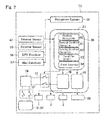
- FIG. 2 is a schematic illustration showing the control system according to the embodiment of the present disclosure.
- FIG. 3 is a flowchart showing a control example executed by the control system according to the embodiment of the present disclosure.
- control system may be applied to a hybrid vehicle powered by an engine and a motor(s), and an electric vehicle powered by the motor(s).
- electric power may be supplied to the motor not only from a battery but also from a fuel cell.
- a prime mover includes an engine 1 , a first motor 2 and a second motor 3 .
- a damper device 5 is disposed on an output shaft 4 of the engine 1 to absorb vibrations resulting from torque pulse.
- the damper device 5 comprises an input member 6 connected to the output shaft 4 of the engine 1 , an output member 7 that is allowed to rotate relatively to the input member 6 , and a plurality of elastic members 8 arranged in a circular manner at regular intervals to transmit torque of the input member 6 to the output member 7 .
- the planetary gear unit 10 comprises a sun gear 11 fitted onto the input shaft 9 , a ring gear 12 arranged concentrically with the sun gear 11 , a plurality of pinion gears 13 interposed between the sun gear 11 and the ring gear 12 , and a carrier 14 supporting the pinion gears 13 while allowing to revolve around the sun gear 11 .
- a first cylindrical shaft 15 extends from the sun gear 11 on the input shaft 9 toward the engine 1 to be connected to the first motor 2 .
- a permanent magnet type synchronous motor having a generating function may be used as the first motor 2 .
- a rotor 2 a is connected to the first cylindrical shaft 15 of the sun gear 11 to be rotated integrally therewith, and a stator 2 b is fixed to a stationary member 16 such as a housing.
- a second cylindrical shaft 17 extends from the ring gear 12 toward the second motor 3 , and a rotor 3 a of the second motor 3 is connected to the second cylindrical shaft 17 to be rotated integrally therewith.
- a stator 3 b of the second motor 3 is fixed to the stationary member 16 such as a housing.
- a leading end of the second cylindrical shaft 17 is connected to an output shaft 18 as a rotary member to be rotated integrally therewith, and a parking gear 19 as an external gear is fitted onto the output shaft 18 to be rotated integrally therewith.
- a parking lock mechanism 20 is arranged outside of the parking gear 19 .
- the parking lock mechanism 20 comprises a parking pawl 21 and a parking actuator 22 .
- the parking actuator 22 may be actuated not only manually by a passenger but also automatically by an electronic control unit (as will be called the “controller” hereinafter) 23 to bring the parking pawl 21 into engagement with the parking gear 19 thereby locking the output shaft 18 .
- An engagement between the parking pawl 21 and the parking gear 19 may be maintained even after shutting down a battery as a power source 24 .
- a leading end of the output shaft 18 is connected to a differential gear unit 25 , and the differential gear unit 25 is connected to a pair of drive wheels 27 through drive shafts 26 extending laterally.
- the drive wheels 27 are turned by a steering system 28 . Rotations of the drive wheels 27 and another pair of wheels 29 are individually stopped by a brake device 30 .
- An operating mode of the vehicle Ve may be selected from a hybrid mode (to be abbreviated as the “HV mode” hereinafter) in which the vehicle Ve is powered at least by the engine 1 , and an electric vehicle mode (to be abbreviated as the “EV mode” hereinafter) in which the vehicle Ve is powered by at least one of the first motor 2 and the second motor 3 .
- the engine 1 generates power in accordance with a required drive force calculated by the controller 23
- the first motor 2 generates reaction torque in such a manner as to deliver the output power of the engine 1 to the drive wheels 27 through the planetary gear unit 10 .
- electric power generated by the first motor 2 may be supplied to the second motor 3 so that an output torque of the second motor may be applied to the second cylindrical shaft 17 . That is, the output power of the engine 1 may be translated partially into the electric power by the first motor 2 , and then translated into kinetic energy again by the second motor 3 to be applied to a torque transmission route R between the engine 1 and the drive wheels 27 .
- the first motor 2 serves as a motor while establishing the reaction torque
- output torque of the first motor 2 applied to the transmission route R may be translated into electric power by the second motor 3 , thereby reducing power transmitted through the transmission route R.
- the second motor 3 is operated as a motor in such a manner as to achieve a required drive force calculated by the controller 23 .
- fuel supply to the engine 1 and power supply to the first motor 2 may be interrupted.
- the first motor 2 is connected to a first inverter 31
- the second motor 3 is connected to a second inverter 32
- the first inverter 31 and the second inverter 32 are also connected to an output terminal of the battery 24 through a positive bus line 33 and a negative bus line 34
- the first motor 2 and the second motor 3 are also connected to each other through the positive bus line 33 and the negative bus line 34 so that electric power generated by one of the motors 2 and 3 is supplied to the other motor 2 or 3 .
- a capacitor 35 for storing electric power is connected parallel to the positive bus line 33 and the negative bus line 34 , and an auxiliary 36 e.g., a compressor for activating an air conditioner is also connected to the positive bus line 33 and the negative bus line 34 .
- a relay switch 37 is individually disposed on the positive bus line 33 and the negative bus line 34 between the output terminal of the battery 24 and the first inverter 31 and the second inverter 32 .
- the relay switch 37 may be turned on and turned off manually by manipulating a switch button or key, but also automatically at desired time by setting a timer or the controller 23 .
- the controller 23 comprises a main controller 38 , a drive controller 39 and a sub-controller 40 .
- Output signals from the main controller 38 are sent to the drive controller 39 and the sub-controller 40 .
- Incident signals to the drive controller 39 are converted into drive commands and further transmitted to a throttle actuator of the engine 1 , the first motor 2 , and the second motor 3 .
- Incident signals to the sub-controller 40 is converted into appropriate command signals and further transmitted to actuators 59 of the brake 30 etc.
- a main switch 41 is arranged between the battery 24 and the drive controller 39 .
- the main switch 41 is turned on, and then, if the switch button is pressed for a predetermined period of time, the relay switch 37 is turned on.
- the main switch 41 is controlled by the main controller 38 to automatically allow and interrupt electric power supply to the drive controller 39 .
- the main controller 38 is an electronic control unit composed mainly of a microcomputer. To the main controller 38 , detection signals and information about operating conditions and behaviors of constituent elements of the vehicle Ve are transmitted from an internal sensor 42 .
- the internal sensor 42 includes an accelerator sensor 44 for detecting a position of an accelerator pedal 43 , a brake sensor (or switch) 46 for detecting a depression of a brake pedal 45 , a steering sensor 48 for detecting a steering angle of the steering wheel 47 , a vehicle speed sensor 49 for detecting rotational speeds of the wheels 27 and 29 , a longitudinal acceleration sensor 50 for detecting a longitudinal acceleration of the vehicle Ve, a lateral acceleration sensor 51 for detecting a lateral acceleration of the vehicle Ve, a yaw rate sensor 52 for detecting a yaw rate of the vehicle, a shift sensor 54 for detecting a position of a shift lever (or switch) 53 and so on.
- the main controller 38 transmits command signals for controlling the engine 1 , the first motor 2 and the second motor 3 to the drive controller 39 , and transmits command signals for controlling the brake 30 and so on to the sub-controller 40 based on incident signals from the internal sensor 42 as well as maps and formulas installed in advance.
- dashed-lines represent transmission of signals between the internal sensor 42 and the controller 23 , and between the controller 23 to the engine 1 , the first motor 2 , the second motor 3 and the brake 30 .
- the vehicle Ve is operated autonomously while manipulating the engine 1 , the first motor 2 , the second motor 3 , the brake 30 and so on by the controller 23 .
- the steering system 28 , the parking lock mechanism 20 and so on are also controlled by the controller 23 .
- the external sensor 55 includes at least one of an on-board camera, a RADAR (i.e., a radio detection and ranging) a LIDAR (i.e., a laser imaging detection and ranging), an ultrasonic sensor and so on.
- a RADAR i.e., a radio detection and ranging
- LIDAR i.e., a laser imaging detection and ranging
- the on-board camera is arranged inside of a windshield glass, and transmits recorded information about the external condition to the main controller 38 .
- a monocular camera but also a stereo camera having a plurality of lenses and image sensors to achieve a binocular vision may be used as the on-board camera. If the stereo camera is used as the on-board camera, the main controller 38 is allowed to obtain three-dimensional information in the forward direction.
- the RADAR is adapted to detect obstacles utilizing radio waves such as millimetric-waves and microwaves, and to transmit detected information to the main controller 38 . Specifically, the RADAR detects an obstacle such as other vehicles and so on by emitting radio waves and analyzing the radio waves reflected from the obstacle.
- the LIDAR is adapted to detect obstacles utilizing laser light and to transmit detected information to the main controller 38 . Specifically, the LIDAR detects an obstacle such as other vehicles and so on by emitting laser light and analyzing the laser light reflected from the obstacle.
- the vehicle Ve is further provided with a GPS (i.e., global positioning system) receiver 56 , a digital map database 57 , and a navigation system 58 .
- the GPS receiver 56 is adapted to obtain a position (i.e., latitude and longitude) based on incident signals from GPS satellites, and to transmit the positional information to the main controller 38 .
- the map database 57 may be installed in the main controller 38 , but map information stored in external online information processing systems may also be available.
- the navigation system 58 is configured to determine a travelling route of the vehicle Ve based on the positional information obtained by the GPS receiver 56 and the map database 57 .
- the main controller 38 carries out calculations based on the incident data or information from the internal sensor 42 and the external sensor 55 as well as the preinstalled data, and calculation results are sent in the form of command signal to the drive controller 39 and the sub-controller 40 .
- the incident signals to the drive controller 39 are converted into drive commands, and further transmitted to the throttle actuator of the engine 1 , and the first inverter 31 and the second inverter 32 of the first motor 2 and the second motor 3 .
- the incident signals to the sub-controller 40 is converted into appropriate command signals and further transmitted to the actuators 59 of the brake 30 , the steering system 28 and so on.
- the actuator 59 includes a brake actuator, a steering actuator and so on.
- the brake actuator is adapted to actuate the brake 30 to control braking force applied to the wheels 27 and 29 in response to reception of the command signal from the sub-controller 40 .
- the steering actuator is adapted to activate an assist motor of the steering system 28 to control a steering torque in response to reception of the command signal from the sub-controller 40 .
- the main controller 38 comprises a position recognizer 60 , an external condition recognizer 61 , a running condition recognizer 62 , a travel plan creator 63 , a travel controller 64 and so on.
- the position recognizer 60 is configured to recognize a current position of the vehicle Ve on the map based on the positional information received by the GPS receiver 56 and the map database 57 .
- the current position of the vehicle Ve may also be obtained from the positional information used in the navigation system 58 .
- the vehicle Ve may also be adapted to communicate with external sensors arranged along the road to obtain the current position of the vehicle Ve.
- the external condition recognizer 61 is configured to recognize external condition of the vehicle Ve such as a location of a traffic lane, a road width, a road configuration, a road gradient, an existence of obstacles around the vehicle Ve and so on, based on the recorded information of the on-board camera, or detection data of the RADAR or the LIDAR.
- weather information, a friction coefficient of road surface etc. may be obtained according to need.
- the running condition recognizer 62 is configured to recognize running condition of the vehicle Ve such as a vehicle speed, a longitudinal acceleration, a lateral acceleration, a yaw rate and so on based on detection result of the internal sensors 42 .
- the travel plan creator 63 is configured to create a travel locus of the vehicle Ve based on a target course determined by the navigation system 58 , a position of the vehicle Ve recognized by the position recognizer 60 , and an external condition recognized by the external condition recognizer 61 . That is, the travel plan creator 63 creates a travel locus of the vehicle Ve within the target course in such a manner that the vehicle Ve is allowed to travel safely and properly while complying traffic rules.
- the travel plan creator 63 is further configured to create a travel plan in line with the created travel locus. Specifically, the travel plan creator 63 creates a travel plan in line with the target course based on the external conditions recognized by the external condition recognizer 61 and the map database 57 .
- the travel plan is created based on prospective data after few seconds from the present moment to determine a future condition of the vehicle Ve such as a driving force or the like required in future.
- the travel plan may also be created based on prospective data after several ten seconds depending on the external conditions and the running conditions.
- the travel plan creator 63 creates a future plan to change a vehicle speed, acceleration, steering torque etc. during travelling along the target course in the form of e.g., a map.
- the travel plan creator 63 may also create a pattern to change the vehicle speed, acceleration, steering torque etc. between predetermined points on the travel locus. Specifically, such patterns may be determined by setting target values of those parameters at each point on the travel locus taking account of a required time to reach the point at the current speed.
- the travel controller 64 is configured to operate the vehicle Ve autonomously in line with the travel plan created by the travel plan creator 63 . To this end, specifically, the travel controller 64 transmits command signals to the actuators 59 , or the engine 1 , the first motor 2 and the second motor 3 through the drive controller 39 and the sub-controller 40 .
- the vehicle Ve may be operated autonomously without a driver to pick up a passenger at a desired pickup location by entering a desired pickup time and location into the main controller 38 .
- the main controller 38 automatically turns on the main switch 41 at a time calculated based on the desired pickup time and location.
- the vehicle Ve may arrive at the pickup location earlier than an estimated time of arrival depending on traffic on the planed route.
- the vehicle Ve has to wait the passenger for a long time while turning on the main switch 41 , activation of the drive controller 39 is maintained while consuming electric power.
- the drive controller 39 has to be started up by turning on the main switch 41 after picking up the passenger, and such procedure takes time. Consequently, the vehicle Ve may not be allowed to launch promptly.
- control system executes a routine shown in FIG. 3 to launch the vehicle Ve promptly after picking up the passenger at the pickup location, and to save electricity while waiting the passenger at the pickup location.
- the routine shown in FIG. 3 is started when the vehicle Ve is launched autonomously to the pickup location to pick up a passenger. First of all, it is determined at step S 1 whether or not the vehicle Ve has arrived at the pickup location. Such determination at step S 1 may be made with reference to a destination entered into the main controller 38 and positional information obtained by the position recognizer 60 .
- step S 2 the routine progresses to step S 2 to continue autonomous propulsion to the pickup location, and then returns.
- step S 3 the routine progresses to step S 3 to maintain the braking forces being applied to the wheels 27 and 29 .
- step S 4 the routine progresses to step S 4 to determine a presence of the passenger within a predetermined area around the vehicle Ve. In other words, at step S 4 , it is determined whether or not a startup of the drive controller 39 can be completed before the passenger gets in the vehicle Ve, or before the vehicle Ve launches after picking up the passenger.
- the predetermined area may be set based on a required period of time to complete a startup of the drive controller 39 , and a required period of time for the passenger to get in the vehicle Ve at the pickup location, or a required period of time to command the vehicle Ve to propel autonomously after the vehicle Ve arrived at the pickup location.
- a presence of the passenger within the predetermined area around the vehicle Ve may be determined based on a fact that: a wireless signal from the key of the vehicle Ve is received by the vehicle Ve; or a door is opened and closed by the passenger.
- occupancy of the vehicle seat may be determined for each seat.
- a pressure sensor may be arranged in each seat to send a signal e.g., to the main controller 38 .
- step S 4 If the control system detects a passenger within the predetermined area around the vehicle Ve so that the answer of step S 4 is YES, the routine progresses to step S 5 to keep the main switch 41 turned on.
- the passenger may not always get in the vehicle Ve promptly.
- the passenger may not always command the vehicle Ve to launch immediately to the next destination.
- the relay switch 37 is continuously turned on, electric power is continuously consumed to supply standby power to the first motor 2 and the second motor 3 as long as the vehicle Ve is stopped.
- the relay switch 37 is turned off, the vehicle Ve is launched after turning on the relay switch 37 . Consequently, commencement of propulsion of the vehicle Ve lags behind a transmission of a command signal to launch the vehicle Ve autonomously.
- the control system compares an elapsed time t 1 from a time point at which the passenger was detected at step S 4 to a time point at which the passenger commands the vehicle Ve to start autonomous propulsion, to a first predetermined period ⁇ that is fundamentally required for the passenger to command the vehicle Ve to start autonomous propulsion from a time point at which the vehicle Ve picks up the passenger. If the elapsed time t 1 is shorter than the first predetermined period ⁇ , the relay switch 37 is maintained to be turned on. By contrast, if the elapsed time t 1 is longer than the first predetermined period ⁇ , the relay switch 37 is turned off. In this case, in order to save time to start the drive controller 39 before launching the vehicle Ve, activation of the drive controller 39 is maintained.
- step S 6 the routine progresses to step S 6 to determine whether or not the elapsed time t 1 is equal to or shorter than the first predetermined period ⁇ . If the elapsed time t 1 is equal to or shorter than the first predetermined period ⁇ so that the answer of step S 6 is YES, the routine progresses to step S 7 to maintain an operating range to a drive range.
- the main switch 41 and the relay switch 37 are continuously turned on, and the braking forces of the brakes 30 applied to the wheels 27 and 29 are maintained.
- step S 8 shift the operating range to a parking range.
- the relay switch 37 is turned off while keeping the main switch 41 to be turned on, and the parking lock mechanism 20 is actuated to engage the parking pawl 21 with the parking gear 19 thereby locking the output shaft 18 .
- the vehicle Ve is brought into a neutral state in which a torque transmission between the engine 1 and the drive wheels 27 is interrupted while stopping a rotation of the output shaft 18 .
- the braking forces of the brakes 30 applied to the wheels 27 and 29 may be reduced.
- step S 9 determines whether or not the vehicle Ve is commanded to propel autonomously to the next destination. For example, such determination at step S 9 may be made based on a fact that the next destination is entered into the navigation system 58 . If the vehicle Ve is commanded to propel autonomously so that the answer of step S 9 is YES, the routine progresses to step S 10 to launch the vehicle Ve autonomously. In this situation, if the operating range is in the drive range, the vehicle Ve is launched autonomously while reducing the braking forces of the brakes 30 . By contrast, if the operating range is in the parking range, the vehicle Ve is launched autonomously by shifting the operating range to the drive range, while disengaging the parking pawl 21 from the parking gear 19 and turning on the relay switch 37 .
- step S 9 the routine returns to step S 6 to repeat the determination of step S 6 .
- steps S 7 and S 9 are repeated until the elapsed time t 1 exceeds the first predetermined period ⁇ . Then, steps S 6 , S 8 and S 9 are repeated until the vehicle Ve is commanded to propel autonomously.
- the vehicle Ve will not start autonomous propulsion from the pickup location and hence it is preferable to interrupt electric power supply to the drive controller 39 so as to save the electric power.
- the vehicle Ve may be launched immediately when picking up the passenger. In this case, it is preferable to maintain the activation of the drive controller 39 to allow the vehicle Ve to launch promptly.
- the control system compares a waiting time t 2 from a time point at which the vehicle Ve arrives at the pickup location to a time point at which the passenger appears within the predetermined area at the pickup location, to a second predetermined period ⁇ that is fundamentally required for the passenger picked up by the vehicle Ve to command the vehicle Ve to start autonomous propulsion from a time point at which the vehicle Ve arrives at the pickup location. That is, the second predetermined period ⁇ is longer than the first predetermined period ⁇ . If the waiting time t 2 is longer than the second predetermined period ⁇ , electric power supply to the drive controller 39 is interrupted. By contrast, if the waiting time t 2 is shorter than the second predetermined period ⁇ , the electric power is continuously supplied to the drive controller 39 .
- step S 11 determines whether or not the waiting time t 2 is equal to or longer than the second predetermined period ⁇ . If the waiting time t 2 is shorter than the second predetermined period ⁇ so that the answer of step S 11 is NO, the routine progresses to step S 5 to keep the main switch 41 turned on. Then, the routine progresses to step S 13 to maintain the braking forces of the brakes 30 being applied to the wheels 27 and 29 , and returns to step S 11 .
- step S 14 the routine progresses to shift the operating range to the parking range. Then, the routine progresses to step S 15 to reduce the braking force of the brakes 30 being applied to the wheels 27 and 29 , and further progresses to step S 16 to turn off the main switch 41 .
- step S 17 determines whether or not the passenger approaches the predetermined area around the vehicle Ve. Such determination at step S 17 may be made based on the same factors as those used at step S 4 . If the passenger does not approach the predetermined area around the vehicle Ve so that the answer of step S 17 is NO, the determination at step S 17 is repeated.
- step S 17 it is also possible to determine boarding of the passenger on the vehicle Ve based on the signal from the pressure sensor arranged in the vehicle seat.
- the main switch 41 is turned on to activate the drive controller 39 . That is, the drive controller 39 has already been started when the passenger gets in the vehicle Ve, or when the passenger commands the vehicle Ve to start autonomous propulsion. In this case, therefore, the vehicle Ve is allowed to promptly start autonomous propulsion.
- the engine 1 may be operated while the vehicle Ve is stopped to charge the battery 24 by operating the first motor 2 as a generator.
- an oil pump and so on may be driven by the engine 1 .
- the relay switch 37 is turned off while maintaining the main switch 41 turned on. That is, electric power supply to the first motor 2 and the second motor 3 is stopped while maintaining activation of the drive controller 39 . In this situation, therefore, the vehicle Ve can be launched promptly upon receipt of a command to propel the vehicle Ve autonomously, and electricity consumption can be reduced until the vehicle Ve is commanded to start autonomous propulsion.
- output power of the engine 1 is delivered to the drive wheels 27 by establishing reaction torque by the first motor 2 .
- the transmission route R is brought into the neutral state by stopping electric power supply to the first motor 2 and the second motor 3 .
- output torque of the engine 1 will not be delivered to the drive wheels 27 and hence the vehicle Ve can be prevented from being propelled unintentionally.
- a power loss resulting from actuating the brake 30 may be reduced by locking the parking gear 19 by the parking lock mechanism 20 .
- the main switch 41 is temporality turned off so that electric power supply to the drive controller 39 is interrupted to save to save the electric power.
- the standby power supplied to the first motor 2 and the second motor 3 can be saved by turning off the relay switch 37 .
- a power loss resulting from actuating the brake 30 may also be reduced by locking the parking gear 19 by the parking lock mechanism 20 .
- torsion in the transmission route between the output shaft 18 and the drive wheels 27 may be eliminated before the boarding of the passenger by reducing the braking forces of the brake devices 30 . Consequently, the passenger will not sense shocks resulting from eliminating the torsion in the transmission route.
- the main switch 41 is turned on again to startup the drive controller 39 .
- the vehicle Ve is allowed to promptly start autonomous propulsion when the passenger gets in the vehicle Ve, or when the passenger commands the vehicle Ve to start autonomous propulsion.
- electric power supply from the battery 24 to the RADAR and the LIDAR may also be interrupted by another relay switch.
- electric power supply to the RADAR and the LIDAR is stopped if the elapsed time t 1 is longer than the first predetermined period ⁇ , or if the waiting time t 2 is longer than the second predetermined period ⁇ to save electricity.
- the RADAR and the LIDAR may be activated when the vehicle Ve is commanded to propel autonomously or when the passenger approaches the predetermined area around the vehicle Ve to launch the vehicle Ve promptly.
Landscapes
- Engineering & Computer Science (AREA)
- Mechanical Engineering (AREA)
- Transportation (AREA)
- Chemical & Material Sciences (AREA)
- Combustion & Propulsion (AREA)
- Automation & Control Theory (AREA)
- Human Computer Interaction (AREA)
- Electric Propulsion And Braking For Vehicles (AREA)
- Traffic Control Systems (AREA)
Abstract
Description
Claims (6)
Applications Claiming Priority (2)
| Application Number | Priority Date | Filing Date | Title |
|---|---|---|---|
| JP2016-167748 | 2016-08-30 | ||
| JP2016167748A JP6428732B2 (en) | 2016-08-30 | 2016-08-30 | Vehicle control device |
Publications (2)
| Publication Number | Publication Date |
|---|---|
| US20180057006A1 US20180057006A1 (en) | 2018-03-01 |
| US10392017B2 true US10392017B2 (en) | 2019-08-27 |
Family
ID=61241540
Family Applications (1)
| Application Number | Title | Priority Date | Filing Date |
|---|---|---|---|
| US15/688,363 Active 2037-09-16 US10392017B2 (en) | 2016-08-30 | 2017-08-28 | Vehicle control system |
Country Status (3)
| Country | Link |
|---|---|
| US (1) | US10392017B2 (en) |
| JP (1) | JP6428732B2 (en) |
| CN (1) | CN107792051B (en) |
Families Citing this family (14)
| Publication number | Priority date | Publication date | Assignee | Title |
|---|---|---|---|---|
| JP6569596B2 (en) * | 2016-05-20 | 2019-09-04 | トヨタ自動車株式会社 | vehicle |
| EP3517346A4 (en) * | 2016-09-21 | 2020-05-06 | NSK Ltd. | Electric vehicle drive device |
| US10922903B2 (en) * | 2017-07-11 | 2021-02-16 | Waymo Llc | Methods and systems for providing remote assistance to a stopped vehicle |
| CN108829083A (en) * | 2018-06-04 | 2018-11-16 | 北京智行者科技有限公司 | Control unit for vehicle |
| CN108762271A (en) * | 2018-06-04 | 2018-11-06 | 北京智行者科技有限公司 | Control unit for vehicle |
| US11506731B2 (en) | 2018-11-27 | 2022-11-22 | Waymo Llc | Motor and rotary transformer with shared magnetic core |
| JP7232067B2 (en) * | 2019-02-07 | 2023-03-02 | 株式会社ジェイテクト | motor controller |
| JP7322536B2 (en) * | 2019-06-14 | 2023-08-08 | マツダ株式会社 | Mobile body control device |
| US11281217B2 (en) | 2019-06-25 | 2022-03-22 | Ford Global Technologies, Llc | Enhanced vehicle operation |
| JP7238641B2 (en) * | 2019-06-28 | 2023-03-14 | トヨタ自動車株式会社 | vehicle starting mechanism |
| JP7238728B2 (en) * | 2019-10-23 | 2023-03-14 | トヨタ自動車株式会社 | Driving support device |
| JP7151743B2 (en) * | 2020-06-18 | 2022-10-12 | トヨタ自動車株式会社 | Vehicle machine learning system |
| JP7548024B2 (en) * | 2021-01-13 | 2024-09-10 | トヨタ自動車株式会社 | Information processing device and program |
| CN112848888A (en) * | 2021-03-02 | 2021-05-28 | 池亚超 | Device and method for preventing motor vehicle from running by cutting off power source so as to ensure safety of vehicle and related personnel |
Citations (9)
| Publication number | Priority date | Publication date | Assignee | Title |
|---|---|---|---|---|
| JPH0672296A (en) | 1992-08-28 | 1994-03-15 | Toyota Motor Corp | Automatic parking device of vehicle |
| JP2007118800A (en) | 2005-10-28 | 2007-05-17 | Toyota Motor Corp | Steering device of vehicle |
| US20130066519A1 (en) | 2011-09-14 | 2013-03-14 | Honda Motor Co., Ltd. | Electronic control device and vehicle control system |
| JP2013159202A (en) | 2012-02-03 | 2013-08-19 | Fuji Heavy Ind Ltd | Vehicle control device |
| JP2014106854A (en) | 2012-11-29 | 2014-06-09 | Toyota Infotechnology Center Co Ltd | Automatic driving vehicle control apparatus and method |
| JP2015120403A (en) | 2013-12-24 | 2015-07-02 | 富士重工業株式会社 | Automatic parking support device |
| WO2015166811A1 (en) | 2014-04-30 | 2015-11-05 | みこらった株式会社 | Automatic driving vehicle and program for automatic driving vehicle |
| US20150339928A1 (en) * | 2015-08-12 | 2015-11-26 | Madhusoodhan Ramanujam | Using Autonomous Vehicles in a Taxi Service |
| US20180208243A1 (en) * | 2015-08-28 | 2018-07-26 | Lg Electronics Inc. | Autonomous driving vehicle |
Family Cites Families (13)
| Publication number | Priority date | Publication date | Assignee | Title |
|---|---|---|---|---|
| JP4059194B2 (en) * | 2003-12-25 | 2008-03-12 | トヨタ自動車株式会社 | Integrated control system for vehicles |
| US8951163B2 (en) * | 2010-03-15 | 2015-02-10 | Toyota Jidosha Kabushiki Kaisha | Control device for vehicle |
| WO2013112546A1 (en) * | 2012-01-23 | 2013-08-01 | Marriott Construction, Inc. | Concrete saw rack having slot to accommodate blade |
| JP5851861B2 (en) * | 2012-01-30 | 2016-02-03 | Ntn株式会社 | Electric car |
| GB201215963D0 (en) * | 2012-09-06 | 2012-10-24 | Jaguar Cars | Vehicle control system and method |
| US8825258B2 (en) * | 2012-11-30 | 2014-09-02 | Google Inc. | Engaging and disengaging for autonomous driving |
| JP5956355B2 (en) * | 2013-01-31 | 2016-07-27 | 株式会社東海理化電機製作所 | Electronic key system |
| JP2015223860A (en) * | 2014-05-26 | 2015-12-14 | 株式会社デンソー | Vehicle control device |
| JP2016047685A (en) * | 2014-08-27 | 2016-04-07 | トヨタ自動車株式会社 | Vehicle roof control apparatus |
| CN105511469B (en) * | 2015-12-18 | 2018-06-15 | 北京联合大学 | A kind of unmanned intelligent patrol electric vehicle and patrol system |
| GB2534471A (en) * | 2015-12-22 | 2016-07-27 | Daimler Ag | Method for operating a motor vehicle by remote control |
| CN105691238B (en) * | 2016-03-01 | 2018-05-15 | 福建省汽车工业集团云度新能源汽车股份有限公司 | A kind of electric automobile automatic ride control method |
| US10206499B2 (en) * | 2016-07-21 | 2019-02-19 | Albert A Purifoy | Multipurpose desk with an integrated computer system |
-
2016
- 2016-08-30 JP JP2016167748A patent/JP6428732B2/en active Active
-
2017
- 2017-08-28 US US15/688,363 patent/US10392017B2/en active Active
- 2017-08-30 CN CN201710762080.8A patent/CN107792051B/en active Active
Patent Citations (11)
| Publication number | Priority date | Publication date | Assignee | Title |
|---|---|---|---|---|
| JPH0672296A (en) | 1992-08-28 | 1994-03-15 | Toyota Motor Corp | Automatic parking device of vehicle |
| JP2007118800A (en) | 2005-10-28 | 2007-05-17 | Toyota Motor Corp | Steering device of vehicle |
| US20130066519A1 (en) | 2011-09-14 | 2013-03-14 | Honda Motor Co., Ltd. | Electronic control device and vehicle control system |
| JP2013062980A (en) | 2011-09-14 | 2013-04-04 | Keihin Corp | Electronic control device and vehicle control system |
| JP2013159202A (en) | 2012-02-03 | 2013-08-19 | Fuji Heavy Ind Ltd | Vehicle control device |
| JP2014106854A (en) | 2012-11-29 | 2014-06-09 | Toyota Infotechnology Center Co Ltd | Automatic driving vehicle control apparatus and method |
| JP2015120403A (en) | 2013-12-24 | 2015-07-02 | 富士重工業株式会社 | Automatic parking support device |
| WO2015166811A1 (en) | 2014-04-30 | 2015-11-05 | みこらった株式会社 | Automatic driving vehicle and program for automatic driving vehicle |
| US20170123423A1 (en) | 2014-04-30 | 2017-05-04 | Mico Latta Inc. | Automatic driving vehicle and program for automatic driving vehicle |
| US20150339928A1 (en) * | 2015-08-12 | 2015-11-26 | Madhusoodhan Ramanujam | Using Autonomous Vehicles in a Taxi Service |
| US20180208243A1 (en) * | 2015-08-28 | 2018-07-26 | Lg Electronics Inc. | Autonomous driving vehicle |
Also Published As
| Publication number | Publication date |
|---|---|
| CN107792051B (en) | 2020-09-08 |
| JP2018036754A (en) | 2018-03-08 |
| CN107792051A (en) | 2018-03-13 |
| US20180057006A1 (en) | 2018-03-01 |
| JP6428732B2 (en) | 2018-11-28 |
Similar Documents
| Publication | Publication Date | Title |
|---|---|---|
| US10392017B2 (en) | Vehicle control system | |
| US11662724B2 (en) | Vehicle control system | |
| US9902393B2 (en) | Vehicle control system | |
| US10065644B2 (en) | Vehicle control system | |
| US20160304124A1 (en) | Vehicle control system | |
| US10576966B2 (en) | Control system for hybrid vehicle | |
| US9896109B2 (en) | Vehicle control system | |
| US9506558B2 (en) | Vehicle control system | |
| US10093300B2 (en) | Vehicle control system | |
| US10343675B2 (en) | Vehicle control system | |
| US10266166B2 (en) | Vehicle control system | |
| US9873434B2 (en) | Vehicle control system | |
| US11029689B2 (en) | Vehicle control system | |
| CN116968735A (en) | Train traveling system | |
| JP2019034581A (en) | Row traveling system | |
| JP2018076047A (en) | Vehicle control system | |
| JP2019079326A (en) | Electric vehicle | |
| US20240300474A1 (en) | Hybrid vehicle control system and method for controlling hybrid vehicle | |
| JP2018025846A (en) | Control device for vehicle | |
| JP2024114193A (en) | Platooning System | |
| JP2024085335A (en) | Control device of hybrid vehicle | |
| JP2024086252A (en) | Column travel system |
Legal Events
| Date | Code | Title | Description |
|---|---|---|---|
| FEPP | Fee payment procedure |
Free format text: ENTITY STATUS SET TO UNDISCOUNTED (ORIGINAL EVENT CODE: BIG.); ENTITY STATUS OF PATENT OWNER: LARGE ENTITY |
|
| AS | Assignment |
Owner name: TOYOTA JIDOSHA KABUSHIKI KAISHA, JAPAN Free format text: ASSIGNMENT OF ASSIGNORS INTEREST;ASSIGNORS:SEKI, YUSHI;HATA, KENSEI;ENDO, TAKAHITO;AND OTHERS;SIGNING DATES FROM 20170915 TO 20171003;REEL/FRAME:043984/0516 |
|
| STPP | Information on status: patent application and granting procedure in general |
Free format text: RESPONSE TO NON-FINAL OFFICE ACTION ENTERED AND FORWARDED TO EXAMINER |
|
| STPP | Information on status: patent application and granting procedure in general |
Free format text: NOTICE OF ALLOWANCE MAILED -- APPLICATION RECEIVED IN OFFICE OF PUBLICATIONS |
|
| STPP | Information on status: patent application and granting procedure in general |
Free format text: AWAITING TC RESP., ISSUE FEE NOT PAID |
|
| STPP | Information on status: patent application and granting procedure in general |
Free format text: NOTICE OF ALLOWANCE MAILED -- APPLICATION RECEIVED IN OFFICE OF PUBLICATIONS |
|
| STPP | Information on status: patent application and granting procedure in general |
Free format text: PUBLICATIONS -- ISSUE FEE PAYMENT VERIFIED |
|
| STCF | Information on status: patent grant |
Free format text: PATENTED CASE |
|
| CC | Certificate of correction | ||
| MAFP | Maintenance fee payment |
Free format text: PAYMENT OF MAINTENANCE FEE, 4TH YEAR, LARGE ENTITY (ORIGINAL EVENT CODE: M1551); ENTITY STATUS OF PATENT OWNER: LARGE ENTITY Year of fee payment: 4 |