US10382089B2 - Systems and methods for intelligently-tuned digital self-interference cancellation - Google Patents
Systems and methods for intelligently-tuned digital self-interference cancellation Download PDFInfo
- Publication number
- US10382089B2 US10382089B2 US16/125,269 US201816125269A US10382089B2 US 10382089 B2 US10382089 B2 US 10382089B2 US 201816125269 A US201816125269 A US 201816125269A US 10382089 B2 US10382089 B2 US 10382089B2
- Authority
- US
- United States
- Prior art keywords
- digital
- signal
- analog
- self
- interference
- Prior art date
- Legal status (The legal status is an assumption and is not a legal conclusion. Google has not performed a legal analysis and makes no representation as to the accuracy of the status listed.)
- Active
Links
- 238000000034 method Methods 0.000 title description 20
- 230000004044 response Effects 0.000 claims abstract description 37
- 238000004891 communication Methods 0.000 claims description 43
- 238000001914 filtration Methods 0.000 claims description 37
- 238000006243 chemical reaction Methods 0.000 claims description 22
- 230000006870 function Effects 0.000 description 33
- 238000012935 Averaging Methods 0.000 description 22
- 239000011159 matrix material Substances 0.000 description 18
- 230000008859 change Effects 0.000 description 13
- 238000013213 extrapolation Methods 0.000 description 12
- 239000004606 Fillers/Extenders Substances 0.000 description 9
- 238000009499 grossing Methods 0.000 description 9
- 230000003068 static effect Effects 0.000 description 9
- 230000005540 biological transmission Effects 0.000 description 8
- 230000000694 effects Effects 0.000 description 5
- 230000007613 environmental effect Effects 0.000 description 5
- 230000008569 process Effects 0.000 description 5
- 238000013459 approach Methods 0.000 description 3
- 238000013528 artificial neural network Methods 0.000 description 3
- 230000008901 benefit Effects 0.000 description 3
- 230000002596 correlated effect Effects 0.000 description 3
- 238000013178 mathematical model Methods 0.000 description 3
- 238000012545 processing Methods 0.000 description 3
- 238000005070 sampling Methods 0.000 description 3
- 230000003595 spectral effect Effects 0.000 description 3
- 238000012360 testing method Methods 0.000 description 3
- 230000009466 transformation Effects 0.000 description 3
- 230000003044 adaptive effect Effects 0.000 description 2
- 239000000969 carrier Substances 0.000 description 2
- 230000003111 delayed effect Effects 0.000 description 2
- 229920005994 diacetyl cellulose Polymers 0.000 description 2
- 238000011478 gradient descent method Methods 0.000 description 2
- 230000036039 immunity Effects 0.000 description 2
- 238000010801 machine learning Methods 0.000 description 2
- 230000004048 modification Effects 0.000 description 2
- 238000012986 modification Methods 0.000 description 2
- 230000010363 phase shift Effects 0.000 description 2
- 230000009467 reduction Effects 0.000 description 2
- 238000001228 spectrum Methods 0.000 description 2
- 230000001131 transforming effect Effects 0.000 description 2
- 235000015429 Mirabilis expansa Nutrition 0.000 description 1
- 244000294411 Mirabilis expansa Species 0.000 description 1
- 241001168730 Simo Species 0.000 description 1
- 230000006978 adaptation Effects 0.000 description 1
- 238000004458 analytical method Methods 0.000 description 1
- 239000003990 capacitor Substances 0.000 description 1
- 230000001413 cellular effect Effects 0.000 description 1
- 238000012937 correction Methods 0.000 description 1
- 230000000875 corresponding effect Effects 0.000 description 1
- 238000000354 decomposition reaction Methods 0.000 description 1
- 230000001419 dependent effect Effects 0.000 description 1
- 238000001514 detection method Methods 0.000 description 1
- 238000003708 edge detection Methods 0.000 description 1
- 238000005516 engineering process Methods 0.000 description 1
- 230000007274 generation of a signal involved in cell-cell signaling Effects 0.000 description 1
- 230000007246 mechanism Effects 0.000 description 1
- 235000013536 miso Nutrition 0.000 description 1
- 238000003062 neural network model Methods 0.000 description 1
- 230000003287 optical effect Effects 0.000 description 1
- 238000012546 transfer Methods 0.000 description 1
- 238000004800 variational method Methods 0.000 description 1
Images


Classifications
-
- H—ELECTRICITY
- H04—ELECTRIC COMMUNICATION TECHNIQUE
- H04B—TRANSMISSION
- H04B1/00—Details of transmission systems, not covered by a single one of groups H04B3/00 - H04B13/00; Details of transmission systems not characterised by the medium used for transmission
- H04B1/38—Transceivers, i.e. devices in which transmitter and receiver form a structural unit and in which at least one part is used for functions of transmitting and receiving
- H04B1/40—Circuits
- H04B1/54—Circuits using the same frequency for two directions of communication
- H04B1/56—Circuits using the same frequency for two directions of communication with provision for simultaneous communication in two directions
-
- H—ELECTRICITY
- H04—ELECTRIC COMMUNICATION TECHNIQUE
- H04B—TRANSMISSION
- H04B1/00—Details of transmission systems, not covered by a single one of groups H04B3/00 - H04B13/00; Details of transmission systems not characterised by the medium used for transmission
- H04B1/06—Receivers
- H04B1/10—Means associated with receiver for limiting or suppressing noise or interference
- H04B1/12—Neutralising, balancing, or compensation arrangements
- H04B1/123—Neutralising, balancing, or compensation arrangements using adaptive balancing or compensation means
-
- H—ELECTRICITY
- H04—ELECTRIC COMMUNICATION TECHNIQUE
- H04B—TRANSMISSION
- H04B1/00—Details of transmission systems, not covered by a single one of groups H04B3/00 - H04B13/00; Details of transmission systems not characterised by the medium used for transmission
- H04B1/38—Transceivers, i.e. devices in which transmitter and receiver form a structural unit and in which at least one part is used for functions of transmitting and receiving
- H04B1/40—Circuits
- H04B1/50—Circuits using different frequencies for the two directions of communication
- H04B1/52—Hybrid arrangements, i.e. arrangements for transition from single-path two-direction transmission to single-direction transmission on each of two paths or vice versa
- H04B1/525—Hybrid arrangements, i.e. arrangements for transition from single-path two-direction transmission to single-direction transmission on each of two paths or vice versa with means for reducing leakage of transmitter signal into the receiver
-
- H—ELECTRICITY
- H04—ELECTRIC COMMUNICATION TECHNIQUE
- H04L—TRANSMISSION OF DIGITAL INFORMATION, e.g. TELEGRAPHIC COMMUNICATION
- H04L25/00—Baseband systems
- H04L25/02—Details ; arrangements for supplying electrical power along data transmission lines
- H04L25/0202—Channel estimation
-
- H—ELECTRICITY
- H04—ELECTRIC COMMUNICATION TECHNIQUE
- H04L—TRANSMISSION OF DIGITAL INFORMATION, e.g. TELEGRAPHIC COMMUNICATION
- H04L27/00—Modulated-carrier systems
- H04L27/26—Systems using multi-frequency codes
- H04L27/2601—Multicarrier modulation systems
- H04L27/2626—Arrangements specific to the transmitter only
- H04L27/2627—Modulators
- H04L27/2628—Inverse Fourier transform modulators, e.g. inverse fast Fourier transform [IFFT] or inverse discrete Fourier transform [IDFT] modulators
-
- H—ELECTRICITY
- H04—ELECTRIC COMMUNICATION TECHNIQUE
- H04L—TRANSMISSION OF DIGITAL INFORMATION, e.g. TELEGRAPHIC COMMUNICATION
- H04L27/00—Modulated-carrier systems
- H04L27/26—Systems using multi-frequency codes
- H04L27/2601—Multicarrier modulation systems
- H04L27/2647—Arrangements specific to the receiver only
-
- H—ELECTRICITY
- H04—ELECTRIC COMMUNICATION TECHNIQUE
- H04L—TRANSMISSION OF DIGITAL INFORMATION, e.g. TELEGRAPHIC COMMUNICATION
- H04L5/00—Arrangements affording multiple use of the transmission path
- H04L5/14—Two-way operation using the same type of signal, i.e. duplex
Definitions
- This invention relates generally to the wireless communications field, and more specifically to new and useful systems and methods for intelligently-tuned digital self-interference cancellation.
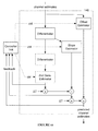
- FIG. 1 is a schematic representation of a full-duplex transceiver
- FIG. 2 is a schematic representation of a system of an invention embodiment
- FIG. 3A is a schematic representation of a digital self-interference canceller of a system of an invention embodiment
- FIG. 3B is a schematic representation of a digital self-interference canceller of a system of an invention embodiment
- FIG. 3C is a schematic representation of a digital self-interference canceller of a system of an invention embodiment
- FIG. 4 is a schematic representation of a digital self-interference canceller of a system of an invention embodiment
- FIG. 5 is a schematic representation of a digital self-interference canceller of a system of an invention embodiment
- FIG. 6 is a schematic representation of a digital self-interference canceller of a system of an invention embodiment
- FIG. 7 is a schematic representation of a digital self-interference canceller of a system of an invention embodiment
- FIG. 8 is a schematic representation of a digital self-interference canceller of a system of an invention embodiment
- FIG. 9A is a plot representation of a self-interference channel estimate
- FIG. 9B is a plot representation of a predicted self-interference channel estimate
- FIG. 10 is a schematic representation of a predictor of a digital self-interference canceller of a system of an invention embodiment
- FIG. 11 is a schematic representation of a predictor of a digital self-interference canceller of a system of an invention embodiment
- FIG. 12 is a schematic representation of a predictor of a digital self-interference canceller of a system of an invention embodiment
- FIG. 13 is a schematic representation of a digital self-interference canceller of a system of an invention embodiment
- FIG. 14 is a schematic representation of a digital self-interference canceller of a system of an invention embodiment
- FIG. 15 is a schematic representation of a digital self-interference canceller of a system of an invention embodiment
- FIG. 16A is a plot representation of a predicted self-interference channel estimate
- FIG. 16B is a plot representation of a time-interpolated predicted self-interference channel estimate
- FIG. 17 is a plot representation of self-interference channel magnitude smoothing
- FIG. 18 is a plot representation of self-interference channel phase smoothing.
- Wireless communications systems have revolutionized the way the world communicates, and the rapid growth of communication using such systems has provided increased economic and educational opportunity across all regions and industries.
- the wireless spectrum required for communication is a finite resource, and the rapid growth in wireless communications has also made the availability of this resource ever scarcer.
- spectral efficiency has become increasingly important to wireless communications systems.
- full-duplex wireless communications systems have substantial value to the wireless communications field, such systems have been known to face challenges due to self-interference; because reception and transmission occur at the same time on the same channel, the received signal at a full-duplex transceiver may include undesired signal components from the signal being transmitted from that transceiver. As a result, full-duplex wireless communications systems often include analog and/or digital self-interference cancellation circuits to reduce self-interference.
- Full-duplex transceivers preferably sample transmission output as baseband digital signals, intermediate frequency (IF) analog signals, or as radio-frequency (RF) analog signals, but full-duplex transceivers may additionally or alternatively sample transmission output in any suitable manner.
- This sampled transmission output may be used by full-duplex transceivers to remove interference from received wireless communications data (e.g., as RF/IF analog signals or baseband digital signals).
- an analog self-interference cancellation system is paired with a digital self-interference cancellation system. The analog cancellation system removes a first portion of self-interference by summing delayed and scaled versions of the RF transmit signal to create an RF self-interference cancellation signal, which is then subtracted from the RF receive signal.
- the analog cancellation system may perform similar tasks at an intermediate frequency. After the RF (or IF) receive signal has the RF/IF self-interference cancellation signal subtracted, it passes through an analog-to-digital converter of the receiver (and becomes a digital receive signal). After this stage, a digital self-interference cancellation signal (created by transforming a digital transmit signal) is then subtracted from the digital receive signal.
- Full-duplex transceivers often include tuning systems that adjust tunable parameters of the analog self-interference cancellation system in order to adapt the analog self-interference cancellation signal to changing self-interference conditions.
- full-duplex transceivers may similarly include tuning systems that alter the transform configuration of digital self-interference cancellation systems for the same purpose.
- the systems and methods described herein increase tuning performance of full-duplex transceivers as shown in FIG. 1 (and other applicable systems) by performing digital self-interference canceller tuning, thus allowing for increased effectiveness in self-interference cancellation.
- Other applicable systems include active sensing systems (e.g., RADAR), wired communications systems, wireless communications systems, and/or any other suitable system, including communications systems where transmit and receive bands are close in frequency, but not overlapping.
- a system 100 for intelligently-tuned digital self-interference cancellation includes a digital self-interference canceller 140 .
- the system 100 may additionally or alternatively include a receiver 100 , a transmitter 120 , a signal coupler 130 , analog-to-digital converters (ADCs) 150 and 151 , a digital-to-analog converter (DAC) 152 , and an analog canceller 160 .
- ADCs analog-to-digital converters
- DAC digital-to-analog converter
- the system 100 functions to increase the performance of self-interference cancellation by performing digital self-interference canceller tuning intelligently based on both transmit signal input and residue signal input. Transmit signal input is used to identify components of a transmit signal likely to be reflected in received self-interference, while residue signal input is used to determine the effects of self-interference cancellation.
- the system 100 is preferably implemented using both digital and analog circuitry.
- Digital circuitry is preferably implemented using a general-purpose processor, a digital signal processor, an application specific integrated circuit (ASIC), a field programmable gate array (FPGA) and/or any suitable processor(s) or circuit(s).
- Analog circuitry is preferably implemented using analog integrated circuits (ICs) but may additionally or alternatively be implemented using discrete components (e.g., capacitors, resistors, transistors), wires, transmission lines, waveguides, digital components, mixed-signal components, or any other suitable components.
- the system 100 preferably includes memory to store configuration data, but may additionally or alternatively be configured using externally stored configuration data or in any suitable manner.
- the receiver 110 functions to receive analog receive signals transmitted over a communications link (e.g., a wireless channel, a coaxial cable).
- a communications link e.g., a wireless channel, a coaxial cable.
- the receiver 110 preferably converts analog receive signals into digital receive signals for processing by a communications system, but may additionally or alternatively not convert analog receive signals (passing them through directly without conversion).
- the receiver 110 is preferably a radio-frequency (RF) receiver substantially similar to the receiver of U.S. patent application Ser. No. 15/362,289, the entirety of which is incorporated by this reference, but may additionally or alternatively be any suitable receiver.
- RF radio-frequency
- the transmitter 120 functions to transmit signals of the communications system over a communications link to a second communications system.
- the transmitter 120 preferably converts digital transmit signals into analog transmit signals.
- the transmitter 120 is preferably a radio-frequency (RF) transmitter substantially similar to the transmitter of U.S. patent application Ser. No. 15/362,289, but may additionally or alternatively be any suitable transmitter.
- RF radio-frequency
- the signal coupler 130 functions to allow signals to be split and/or joined.
- the signal coupler 130 may be used to provide a sample of the analog transmit signal for the digital canceller 140 and/or analog cancellers 160 ; that is, the signal coupler 130 may serve as a transmit coupler.
- the signal coupler 130 may also be used to combine one or more analog self-interference cancellation signals (from analog/digital cancellers) with the analog receive signal; that is, the signal coupler 130 may serve as a receive coupler. Additionally or alternatively, the signal coupler 130 may be used for any other purpose. For example, as shown in FIG.
- a signal coupler 130 may be used to provide a sample of a residue signal (in this case, an analog receive signal that has already been combined with an analog self-interference cancellation signal) to the digital canceller 140 .
- the signal coupler 130 is preferably substantially similar to the signal coupler of U.S. patent application Ser. No. 15/362,289, but may additionally or alternatively be any suitable signal coupler.
- the digital self-interference canceller 140 functions to produce a digital self-interference cancellation signal from a digital transmit signal, as shown in FIG. 3A , FIG. 3B , and FIG. 3C .
- the digital self-interference cancellation signal is preferably converted to an analog self-interference cancellation signal (by the DAC 152 ) and combined with one or more analog self-interference cancellation signals to further reduce self-interference present in the RF receive signal at the receiver 110 .
- the digital self-interference cancellation signal may be combined with a digital receive signal (e.g., after the receiver 110 , as shown in FIG. 1 ).
- the digital self-interference canceller 140 preferably samples the RF transmit signal of the transmitter 120 using the ADC 150 (additionally or alternatively, the canceller 140 may sample the digital transmit signal or any other suitable transmit signal) and transforms the sampled and converted RF (or IF) transmit signal to a digital self-interference signal based on a digital transform configuration.
- the digital transform configuration preferably includes settings that dictate how the digital self-interference canceller 140 transforms the digital transmit signal to a digital self-interference signal (e.g. coefficients of a generalized memory polynomial used to transform the transmit signal to a self-interference signal).
- digital self-interference canceller 140 may be coupled to any transmit and/or receive signals (either as input to the canceller or as outputs of the canceller), as described in U.S. patent application Ser. No. 14/569,354, the entirety of which is incorporated by this reference.
- the digital self-interference canceller may take as input an RF-sourced intermediate frequency (IF) transmit signal (e.g., the transmit signal is converted to RF by the transmitter 120 , then downconverted to IF by a downcoverter, then passed through the ADC 150 to the digital canceller 140 ) or may output at IF (e.g., the digital self-interference cancellation signal is converted to a digitally-sourced IF self-interference cancellation signal, and is then combined with an IF self-interference cancellation signal at IF, before the combined self-interference cancellation signal is converted to RF and combined with an RF receive signal).
- IF intermediate frequency
- the digital self-interference canceller 140 may be implemented using a general-purpose processor, a digital signal processor, an application specific integrated circuit (ASIC), a field programmable gate array (FPGA) and/or any suitable processor(s) or circuit(s).
- the digital self-interference canceller 140 preferably includes memory to store configuration data, but may additionally or alternatively be configured using externally stored configuration data or in any suitable manner.
- the digital self-interference canceller 140 preferably includes a filter 142 , a channel estimator 143 , a controller 144 , and channel memory 145 , as shown in FIG. 3 A, FIG. 3B , and FIG. 3C .
- the digital self-interference canceller may additionally or alternatively include a transformer 141 , a predictor 146 , and/or an extender 147 .
- the transformer 141 functions to transform signals (e.g., a digital transmit signal, an output signal of the canceller 140 ) into an alternate-basis representation to perform some function (generally, to calculate the self-interference channel before transforming the channel back into the original representation).
- signals e.g., a digital transmit signal, an output signal of the canceller 140
- an alternate-basis representation to perform some function (generally, to calculate the self-interference channel before transforming the channel back into the original representation).
- transformers 141 may be used to convert time-domain input signals into the frequency domain (via a Fourier transform).
- the Fourier-transformed input is used to generate a self-interference cancellation signal, which is then converted back to the time domain by another transformer 141 .
- the Fourier transform may be performed using a Discrete Fourier Transform (DFT) matrix.
- the inverse Fourier transform may be calculated using the pseudo-inverse of the DFT matrix; i.e., an Inverse Discrete Fourier Transform (IDFT) matrix. Calculating the IDFT using the DFT without modification results in the same number of time domain signal components generated (e.g., ‘taps’ of the self-interference cancellation channel) as frequency points in the original DFT.
- DFT Discrete Fourier Transform
- IDFT Inverse Discrete Fourier Transform
- a transformer 141 may perform the IFFT using a reduced IDFT matrix calculated by first reducing the number of time and frequency domain components (e.g., zeroing out parts of the matrix, neglecting parts of the matrix) present in the DFT matrix and then calculating the pseudo-inverse of this reduced DFT matrix to generate the reduced IDFT matrix.
- Frequency and time domain components may be removed in any manner and to accomplish any goal.
- time domain components may be removed to match a certain solution size (e.g., 64 taps), and frequency components may be removed if they are not considered frequencies of particular interest (e.g., as determined from a lookup table of which receive frequencies are important, by measuring the accuracy of self-interference cancellation at different frequencies, by measuring the amount of self-interference present at different signals, etc.).
- DFT matrix reduction may be performed in any way.
- the transformer 141 may perform Fourier (or inverse Fourier) transforms as a basis-changing technique, the transformer 141 may additionally or alternatively perform any suitable basis-changing transformation. For example, many components of the self-interference channel solution may be correlated; this correlation can result in slow convergence of transform configuration parameters. Resultantly, in one implementation of a preferred embodiment, the transformers 141 may orthogonalize (or otherwise decorrelate) input components using a decorrelation matrix. For example, this decorrelation may be performed using a static decorrelation matrix based on a Gaussian input distribution (or other expected signal distribution) for a given transmission power or using a static decorrelation matrix based on subtraction of expected transmission power; e.g.,
- [ s 1 ⁇ s 3 ⁇ s 5 ⁇ ] [ 1 0 0 - 3 ⁇ ⁇ 2 1 0 ( 15 ⁇ ⁇ 4 ) - 10 ⁇ ⁇ 2 1 ] * [ s 1 ⁇ s 1 ⁇ 2 * s 1 ⁇ s 1 ⁇ 4 * s 1 ] where ⁇ 2 is the power of the linear transmit signal s 1 .
- Transformers 141 may alternatively perform decorrelation using any other method, including using singular value decomposition (SVD), a dynamically computed decorrelation matrix, and/or a matrix similar to the above exemplified static matrix, except with expected power computed dynamically.
- SVD singular value decomposition
- a dynamically computed decorrelation matrix e.g., a matrix similar to the above exemplified static matrix, except with expected power computed dynamically.
- the filter 142 functions to reduce noise in the signals received at the filter.
- the filter 142 may receive a transmit signal Tx and a residue signal Rxr (the receive signal Rx after digital self-interference cancellation), as shown in FIG. 3A .
- the filter 142 may receive any signals relevant to interference cancellation (e.g., Rx instead of Rxr, or a ratio of signals; e.g., Rxr/Tx).
- the filter 142 may additionally or alternatively pass signals without filtering.
- the filter 142 may pass a digital transmit signal without filtering it. Further, if the filter 142 outputs a signal based on the same content to different destinations, the filter 142 may filter the signal differently based on the destination.
- the filter 142 may output a first filtered digital residue signal to the controller 144 and a second filtered digital residue signal to the channel estimator 143 , and the parameters of filtering (and thus the output signals themselves) may be non-identical between the first and second filtered digital residue signals.
- the filter 142 preferably reduces input noise by performing time-averaging of input signals to prepare the signals for self-interference cancellation signal generation.
- the filter 142 may perform time-averaging in any manner; e.g., block averaging, moving averaging, infinite impulse response (IIR) filtering, etc.
- Time averaging functions to reduce the effect of noise in channel estimates (e.g., as Z varies independent of H).
- the controller 144 preferably dynamically adjusts the number of samples the filter 142 uses to perform averaging (i.e., the averaging window) to improve canceller 140 performance. Larger sampling windows allow for increased immunity to noise, but at the cost of ability to track rapid self-interference channel variation.
- the controller 144 may additionally or alternatively vary any aspect of filtering.
- the filter 142 may additionally or alternatively perform any signal transformation to aid in preparing input signals for self-interference cancellation.
- the filter 142 may perform sample rate conversion of signals, scaling, shifting, and/or otherwise modifying signals.
- the filter 142 modifies sampled digital transmit signals by removing information unlikely to substantially affect the output of the channel estimator 143 . This may include, for instance, dropping samples if the samples do not represent a change above some change threshold from previous samples. As another example, if digital transmit signals correspond to a particular amplitude of an output analog signal, only digital signal data corresponding to an amplitude above some amplitude threshold may be passed to the channel estimator 143 .
- the filter 142 may additionally or alternatively combine the signals in any suitable way or may select one signal over another. For instance, the filter 142 may pass the average of the two signals to the estimator 143 . As another example, the filter 142 may prefer an RF-sourced digital transmit signal (e.g., from the ADC 150 ) over the transmit-path digital transmit signal (e.g., sampled before conversion by the transmitter 120 ) above a certain transmitter power, and vice versa at or below that transmitter power. The selection and combination of the two (or more) signals may be dependent on any suitable condition.
- the filter 142 preferably passes both the digital transmit signal and the digital residue (i.e., the digital receive signal after the digital receive signal has been combined with the digital self-interference cancellation signal output by the system 100 ) but may additionally or alternatively pass any signals (e.g., a combination of transmit and residue, receive signal prior to combination with self-interference cancellation signal, etc.).
- the digital transmit signal after filtering may be referred to as a reduced-noise digital transmit signal; likewise, if the residue is filtered, it may be referred to as a reduced-noise residue signal.
- the channel estimator 143 functions to generate a current self-interference cancellation channel estimate ( ⁇ ) from the output of the filter 142 or from any other suitable signal source.
- the channel estimator 143 preferably generates a channel estimate from a weighted sum of signal components according to mathematical models adapted to model self-interference contributions of the RF transmitter, RF receiver, and/or other sources.
- mathematical models that may be used by the channel estimator 143 include generalized memory polynomial (GMP) models, Volterra models, and Wiener-Hammerstein models; the channel estimator 143 may additionally or alternatively use any combination or set of models.
- the channel estimator 143 may additionally or alternatively use generated mathematical models for modeling self-interference contributions based on comparisons of sampled digital transmit signals to received signals (from the receive path or any other suitable source). These models may be generated from previously known models or may be created using neural network and/or machine learning techniques.
- the channel estimator 143 preferably performs channel estimate generation according to a transform configuration set dynamically by the controller 144 (discussed in more detail in sections covering the controller 144 ). Additionally or alternatively, the channel estimator 143 may combine signal components in any manner in order to generate a self-interference channel estimate.
- the channel estimator 143 preferably generates the self-interference channel estimate from a ratio of residue and transmit signals (e.g., Rxr/Tx) but may additionally or alternatively generate self-interference channel estimates from any signal data.
- the channel estimator 143 may also generate a self-interference cancellation signal by combining a digital transmit signal and the self-interference channel estimate (e.g., as shown in FIG. 3B ).
- the channel estimator 143 may pass the self-interference channel estimate along with the transmit signal without combining the two (e.g., as shown in FIG. 3A ).
- the channel estimator 143 may pass the self-interference channel estimate without passing the transmit signal.
- the channel estimator 143 may pass any signal data relevant to self-interference cancellation.
- the digital self-interference canceller 140 preferably includes a single channel estimator 143 , but may additionally or alternatively include multiple channel estimators 143 .
- the digital self-interference canceller 140 may include one channel estimator 143 for linear self-interference cancellation and one for non-linear self-interference cancellation, as shown in FIG. 5 .
- Signal components may be transmitted to multiple channel estimators 143 in any manner. If the canceller 140 includes multiple channel estimators 143 , the output of these filters may be combined in any manner to generate a self-interference cancellation signal.
- the controller 144 functions to set the transform configuration of the channel estimator 143 .
- the controller 144 may additionally or alternatively set configuration of the filter 142 .
- the transform configuration preferably includes the type of model or models used by the channel estimator 143 as well as configuration details pertaining to the models (each individual model is a model type paired with a particular set of configuration details). For example, one transform configuration might set the channel estimator 143 to use a GMP model with a particular set of coefficients. If the model type is static, the transform configuration may simply include model configuration details; for example, if the model is always a GMP model, the transform configuration may include only coefficients for the model, and not data designating the model type.
- the transform configuration may additionally or alternatively include other configuration details related to the filter 142 and/or the channel estimator 143 .
- the controller 144 may set the number of these transform paths, which model order their respective component generators correspond to, and/or any other suitable details.
- the transform configuration may include any details relating to the computation or structure of the filter 142 and/or the channel estimator 143 .
- Transform configurations are preferably selected and/or generated by the controller 144 .
- the controller 144 may set an appropriate transform configuration by selecting from stored static configurations, from generating configurations dynamically, or by any other suitable manner or combination of manners. For example, the controller 144 may choose from three static transform configurations based on their applicability to particular signal and/or environmental conditions (the first is appropriate for low transmitter power, the second for medium transmitter power, and the third for high transmitter power). As another example, the controller 144 may dynamically generate configurations based on signal and/or environmental conditions; the coefficients of a GMP model are set by a formula that takes transmitter power, temperature, and receiver power as input.
- the controller 144 preferably sets transform configurations based on a variety of input data (whether transform configurations are selected from a set of static configurations or generated according to a formula or model).
- Input data used by the controller 144 may include static environmental and system data (e.g. receiver operating characteristics, transmitter operating characteristics, receiver elevation above sea-level), dynamic environmental and system data (e.g. current ambient temperature, current receiver temperature, average transmitter power, ambient humidity), and/or system configuration data (e.g. receiver/transmitter settings), signal data (e.g., digital transmit signal, RF transmit signal, RF receive signal, digital receive signal).
- static environmental and system data e.g. receiver operating characteristics, transmitter operating characteristics, receiver elevation above sea-level
- dynamic environmental and system data e.g. current ambient temperature, current receiver temperature, average transmitter power, ambient humidity
- system configuration data e.g. receiver/transmitter settings
- signal data e.g., digital transmit signal, RF transmit signal, RF receive signal, digital receive signal.
- the controller 144 may additionally or alternatively generate and/or use models based on this input data to set transform configurations; for example, a transmitter manufacturer may give a model to predict internal temperature of the transmitter based on transmitter power, and the controller 144 may use the output of this model (given transmitter power) as input data for setting transform configurations.
- the controller 144 When utilizing digital residue signals, the controller 144 preferably utilizes an un-filtered digital residue signal (as shown in FIGS. 3A and 3B ), but may additionally or alternatively utilize a filtered digital residue signal (as shown in FIG. 3C ). Likewise, any input signal data used by the controller 144 may be in raw form, in processed form, or in any other form.
- the digital residue signal used by the controller may be referred to as a controller-sampled digital residue signal.
- the controller 144 may set transform configurations at any time, but preferably sets transform configurations in response to either a time threshold or other input data threshold being crossed. For example, the controller 144 may re-set transform configurations every ten seconds according to changed input data values. As another example, the controller 144 may re-set transform configurations whenever transmitter power thresholds are crossed (e.g. whenever transmitter power increases by ten percent since the last transform configuration setting, or whenever transmitter power increases over some static value).
- the controller 144 may cooperate with the analog canceller 160 (for instance, setting transform configurations based on data from the analog canceller 160 , coordinating transform configuration setting times with the analog canceller 160 , disabling or modifying operation of the analog canceller 160 ) to reduce overall self-interference (or for any other suitable reason).
- the analog canceller 160 for instance, setting transform configurations based on data from the analog canceller 160 , coordinating transform configuration setting times with the analog canceller 160 , disabling or modifying operation of the analog canceller 160 ) to reduce overall self-interference (or for any other suitable reason).
- the controller 144 preferably adapts transform configurations and/or transform-configuration-generating algorithms (i.e., algorithms that dynamically generate transform configurations) to reduce self-interference for a given transmit signal and set of system/environmental conditions.
- the controller 144 may adapt transform configurations and/or transform-configuration-generating algorithms using analytical methods, online gradient-descent methods (e.g., LMS, RLMS), and/or any other suitable methods.
- Adapting transform configurations preferably includes changing transform configurations based on learning. In the case of a neural-network model, this might include altering the structure and/or weights of a neural network based on test inputs. In the case of a GMP polynomial model, this might include optimizing GMP polynomial coefficients according to a gradient-descent method.
- the controller 144 may adapt transform configurations based on test input scenarios (e.g. scenarios when the signal received by the RF receiver is known), scenarios where there is no input (e.g. the only signal received at the RF receiver is the signal transmitted by the RF transmitter), or scenarios where the received signal is unknown. In cases where the received signal is an unknown signal, the controller 144 may adapt transform configurations based on historical received data (e.g. what the signal looked like ten seconds ago) or any other suitable information.
- test input scenarios e.g. scenarios when the signal received by the RF receiver is known
- scenarios where there is no input e.g. the only signal received at the RF receiver is the signal transmitted by the RF transmitter
- scenarios where the received signal is unknown.
- the controller 144 may adapt transform configurations based on historical received data (e.g. what the signal looked like ten seconds ago) or any other suitable information.
- the controller 144 may additionally or alternatively adapt transform configurations based on the content of the transmitted signal; for instance, if the transmitted signal is modulated in a particular way, the controller 144 may look for that same modulation in the self-interference signal; more specifically, the controller 144 may adapt transform configurations such that when the self-interference signal is combined with the digital receive signal the remaining modulation (as an indicator of self-interference) is reduced (compared to a previous transform configuration).
- the controller 144 may additionally or alternatively function to set tuning parameters for components outside of the digital self-interference canceller 140 , particularly if those parameters are relevant to digital self-interference canceller performance and/or tuning.
- the controller 144 may also be used to change other parameters surrounding digital self-interference cancellation. For example, the controller 144 may be used to modify the size of the averaging window (i.e., number of samples used to perform averaging) of a filter 142 in response to estimated channel characteristics.
- the controller 144 may be used to modify the size of the averaging window (i.e., number of samples used to perform averaging) of a filter 142 in response to estimated channel characteristics.
- the controller 144 modifies the averaging window based on channel power. For example, the controller 144 may modify the averaging window based on the magnitude of
- the controller 144 may use any signal power (e.g., magnitude of Tx) to modify the averaging window.
- the controller 144 may select averaging windows based on the value of power (e.g., higher power ⁇ larger window), the rate of change of power (e.g., higher
- rate of change of power may be found using channel update power (e.g., the difference in estimated channel power between channel updates).
- the controller 144 modifies the averaging window based on a channel dynamics estimation ⁇ is preferably a metric that differentiates between the two aforementioned scenarios (e.g., ⁇ 0 when changes in Z are much larger than changes in H, ⁇ 1 when changes in H are much larger than changes in Z).
- ⁇ may approach a first value as the ratio of dH/dt becomes larger than dZ/dt and a second value in the opposite case (dZ/dt becomes larger than dH/dt).
- test ⁇ may differentiate between these two types of change by looking at correlation across frequency in the power change; while dynamic channel change is correlated across frequency, noise change is generally not.
- ⁇ is a correlation coefficient written as:
- Any metric measuring correlation across frequency and/or time may be used as an alternative metric for ⁇ .
- the controller 144 may modify averaging window in any manner based on ⁇ . For example, the controller 144 may set a smaller averaging window if ⁇ approaches 1 (resulting in faster updates) or a larger averaging window if ⁇ approaches 0 (resulting in more immunity to noise).
- the controller 144 may additionally or alternatively use channel estimates (or other self-interference channel information) from any other source.
- the controller 144 may set averaging windows based on channel estimates received from channel memory, as shown in FIG. 6 .
- the channel estimate used is less noisy; however, this noise may be colored due to Fourier transforms, which in turn may make the correlation metric less reliable.
- the controller 144 may set averaging windows based on channel estimates received from the total updated channel, as shown in FIG. 7 .
- the channel noise is white and can be easily extended to architectures where the entire channel is re-estimated every update (as opposed to incremental updates); however, the noise variance is higher (and thus adaptive thresholds may be needed).
- the controller 144 may set averaging windows based on channel estimates received from the time-domain (and potentially extended) total updated channel, as shown in FIG. 8 .
- the noise variance is smaller and requires fewer computations; however, the out-of-band channel influences the correlation metric, making it potentially less reliable.
- the channel memory 145 functions to hold data relating to past self-interference channel estimates.
- the channel memory 145 functions to store the last known self-interference channel for each subchannel (or any other representation of the full self-interference channel) which may be combined with an incremental update generated by the channel estimator 143 to create a new full channel estimate. As shown in FIG. 3A , this new full channel estimate is then sent to the channel memory 145 , where it may be stored as the most recent self-interference channel estimate.
- the channel estimate stored by the channel memory may be transformed before storage; however, additionally or alternatively the channel memory 145 may be updated directly from the combination of the channel memory 145 output and the channel estimator 143 output.
- the digital self-interference canceller 140 may combine channel estimates from channel memory 145 with the output of the channel estimator 143 in any manner.
- the digital self-interference canceller 140 may replace a section (e.g., a sub-band) of a past channel estimate with the output of the channel estimator 143 .
- the channel estimator 143 may average the output of the channel estimator 143 and the channel memory 145 within a sub-band of relevance.
- the predictor 146 functions to predict a future self-interference cancellation channel estimate from current and/or past self-interference cancellation channel estimates. Because performing cancellation tuning takes time, any tuning on a varying self-interference channel is obsolete as soon as it is complete.
- the predictor 146 preferably modifies the output of the channel estimator 143 to compensate for some or all of the delay incurred by the tuning process. Additionally or alternatively, the predictor 146 may predict future self-interference cancellation channels in order to increase time in between tuning for the canceler 140 .
- the estimated channel lags behind actual channel.
- the predictor 146 may modify the estimated channel based on past channel estimates, leading to a predicted channel, as shown in FIG. 9B . This may result in a significant reduction of error.
- the predictor 146 may attempt to compensate for a known or estimated tuning delay (e.g., the delay between sampling a signal and estimating the self-interference channel from that signal), but may additionally or alternatively extrapolate the self-interference channel into the future by any amount of time (e.g., a time less than or greater than the aforementioned delay). Extrapolation may be performed using instantaneous time deltas, but may additionally or alternatively be performed using filtered time deltas (e.g., averaging measured time deltas). For example, using instantaneous time deltas, the predictor 146 may perform extrapolation for a given self-interference channel estimate based on the difference between the time at which the digital transmit signal and residue signal were sampled and the time that a channel estimate was generated. Likewise, using filtered time deltas, the predictor 146 may perform extrapolation based on the average of several such differences (e.g., the most recent three differences).
- a known or estimated tuning delay e.g., the delay between sampling a
- the predictor 146 preferably predicts self-interference channel data on a per-subcarrier (or per sub-band) basis (i.e., the self-interference channel of each subcarrier is predicted independently). Alternatively, the predictor 146 may jointly predict time and frequency variance of the self-interference channel (discussed in later sections).
- the predictor 146 preferably performs linear extrapolation of the channel, but may additionally or alternatively perform any type of extrapolation (e.g., quadratic).
- the predictor 146 may additionally or alternatively perform signal prediction using any technique (e.g., Weiner filtering, MMSE prediction, adaptive filtering techniques such as LMS and RLS, or neural network/machine learning based techniques).
- the predictor 146 includes an offset estimator, a differentiator, and a slope estimator, as shown in FIGURE to.
- the offset estimator and slope estimator are preferably infinite impulse response (IIR) low-pass filters, but additionally or alternatively, the estimators may be any suitable transformers capable of determining the slope and offset (i.e., the linear characteristics) of the self-interference channel.
- the estimators are preferably controlled by the controller 144 in response to feedback received at the controller, but may additionally or alternatively be controlled in any manner.
- the time ⁇ T represents the amount of extrapolation desired. This concept may be extended to any order; for example a predictor 146 including a 2 nd derivative estimator is as shown in FIG. 11 .
- the predictor 146 may additionally or alternatively predict self-interference channels in non-Cartesian coordinates.
- the predictor 146 may transform self-interference channel estimates from Cartesian to polar coordinates, perform time extrapolation, and then convert back from polar to Cartesian coordinates.
- the predictor 146 preferably performs prediction on a per sub-carrier basis. In many communication schemes (e.g., LTE), even during periods of activity, not every sub-carrier is scheduled every symbol. There are two primary consequences that pertain to the predictor 146 . The first is that if a sub-carrier is not active, prediction may not be useful until that sub-carrier is active again. The second is that if a substantial amount of inactive time passes, the incremental self-interference channel for that sub-carrier is often not accurately represented by an extrapolation of stale data. Further, the presence of stale data may cause new channel estimates to converge slowly.
- LTE long term evolution
- the predictor 146 preferably addresses these issues by tracking the activity of each subcarrier and managing predictor state (for each sub-carrier) based on this activity.
- the predictor 146 preferably monitors the most recent times when each sub-carrier was scheduled.
- the prediction for that sub-carrier is disabled. This is referred to as the RESET state. Additionally, the memory for that prediction may be cleared (preventing stale data from influencing later prediction).
- prediction is enabled in the WARMUP state.
- prediction begins estimating channel parameters (e.g., slope and offset), but does not yet modify the channel estimate based on these parameters.
- WARMUP e.g., by passing a time threshold, by reaching a threshold parameter convergence
- prediction is enabled in the NOMINAL state (where prediction operates as normal).
- NOMINAL where prediction operates as normal.
- prediction output and state many be managed in any way. For example, prediction may be turned on for linear components of the self-interference channel, but disabled for higher order components of the self-interference channel.
- Predicting channel estimates may have additional challenges when sub-carriers are not uniformly sampled in time.
- the predictor 146 scales differential values based on latched timestamps to compensate for non-uniform sampling, as shown in FIG. 12 .
- ⁇ T 1 is the time at which prediction is desired minus the current time
- ⁇ T 2 is the current time minus the previous update time.
- the predictor 146 has been described in some implementations as a combination of digital elements (see e.g., FIGS. 10-12 ), the predictor 146 may additionally or alternatively be implemented in any way; for example, as an end-to-end transfer function performing prediction.
- the predictor 146 preferably performs prediction in the frequency domain, as shown in FIG. 13 .
- the predictor 146 may perform prediction in the time domain, as shown in FIG. 14 . This can reduce the complexity of prediction (because the time domain solution is generally smaller than the frequency domain solution), but may also diminish the ability to control for prediction on a sub-carrier basis.
- the predictor 146 may occur after the channel estimate has been converted to time domain and then back again to frequency domain (e.g., denoising), as shown in FIG. 15 . While denoising leads to a cleaner prediction, it may also increase prediction complexity.
- the predictor 146 may extrapolate for a given subcarrier based not only on historical channel data for that subcarrier, but also for neighboring subcarriers. This may be particularly useful for communications systems where sub-carriers are scheduled intermittently.
- the predictor 146 may additionally perform time-domain interpolation to bridge between frequency-domain extrapolations.
- time-domain interpolation To exemplify this, consider a purely frequency domain example of the predictor. A first estimate of the channel is given at to, and a second estimate of the channel is estimated to occur at t 1 .
- the self-interference channel is predicted on an extrapolation of the channel estimate at t 0 extrapolated by
- ⁇ ⁇ ⁇ T t 1 - t 0 2 , as shown in FIG. 16A .
- This channel estimate is used until the second estimate of the channel is received (if the extrapolation is close to reality, self-interference performance will be best at t 0 + ⁇ T, and not as good elsewhere).
- the extender 147 functions to extend self-interference channel estimates to smooth estimate edges (e.g., if a self-interference channel is calculated for a particular band and zero outside of that band, there may be a discontinuity or sharp edge at the band edge). Edges or other rapidly-varying features may require a large number of components to accurately implement the channel estimate in the time domain (e.g., in the interference canceller 140 ). Thus, it may be desirable to smooth such features in the frequency domain representation of the self-interference channel prior to converting the channel estimate to a time domain representation, in order to simplify the time domain representation of the transform in the canceller 140 .
- a first such variation is to compute the local derivative of the response vs. frequency (e.g., using a finite-differencing scheme) at each frequency value of the response, and to consider an “edge” to be located at any frequency where the local derivative exceeds a particular threshold.
- a local slope that is sufficiently “steep” i.e., has a sufficiently large first derivative
- a related variation includes computing the local first derivative only within frequency bands of the response where sharp variations are known to occur, in order to reduce the computation time of edge detection.
- locating edges or other abrupt changes may include one or a combination of step detection algorithms, such as o-degree spline fitting, piecewise constant denoising, and variational methods (e.g., the Potts model). Additionally or alternatively, abrupt changes in the responses requiring smoothing can be located in any other suitable manner.
- the extender 147 preferably includes smoothing the magnitude response of a self-interference channel estimate.
- exponential decay functions are matched to edges (i.e., where the derivative of magnitude response vs. frequency exceeds a threshold) of the magnitude response.
- other functions may additionally or alternatively be matched to the edges of the magnitude response, such as a polynomial function, a cubic spline, or any other suitable smoothly varying function.
- the function used is preferably selected in order to minimize the number of components needed to represent the transform in the time domain, but can alternatively be selected for any suitable reason.
- the extender 147 may also extrapolate or otherwise modify magnitude response of an estimate in any manner, including performing curve fitting on portions of the magnitude response of an estimate.
- the extender 147 may also filter portions of the magnitude response of the estimate (e.g., median filtering, convolution filtering, and/or any other suitable smoothing filtering).
- the extender 147 preferably also smooths the phase response of the transform.
- phase is extrapolated linearly between edges of phase response (i.e., where the derivative of phase response vs. frequency exceeds a threshold).
- the extender 147 may also extrapolate or otherwise modify phase response of an estimate in any manner, including performing curve fitting on portions of the phase response of an estimate.
- the extender 147 may also filter portions of the phase response of the estimate (e.g., median filtering, convolution filtering, and/or any other suitable smoothing filtering).
- the digital self-interference canceller 140 may additionally or alternatively include any other components as described in U.S. patent application Ser. No. 15/362,289, e.g., blocker filters, filter inverters, etc.
- the digital self-interference canceller 140 may additionally or alternatively include gain/phase compensators that function to modify the gain and phase of either the digital receive signal or the digital self-interference cancellation signal such that the two signals are aligned in gain and phase. Gain/phase compensation thus enables the canceller 140 to compensate for gain and/or phase error induced by the receive chain (or other sources).
- Gain/phase correction values are preferably set by the controller 144 , but may additionally or alternatively be set in any manner.
- the ADC 150 functions to convert a transmit signal from an analog signal to a digital signal; this signal is hereafter referred to as a converted transmit signal.
- the signal post-conversion may be referred to as an RF-sourced digital transmit signal (assuming conversion from an RF transmit signal) or an IF-sourced digital transmit signal (assuming conversion from an IF transmit signal).
- the ADC 150 is preferably substantially similar to the ADC 111 , but may additionally or alternatively be any suitable ADC.
- the ADC 150 may perform signal scaling (in either analog or digital domains) as well as frequency conversion (in either analog or digital domains) for input analog signals.
- the ADC 150 includes at least one of a variable-gain amplifier (VGA) and a digital scaler.
- VGA variable-gain amplifier
- the variable-gain amplifier functions to scale an analog signal before conversion via the ADC 150
- the digital scaler functions to scale a digital signal after conversion via the ADC 150 .
- Both the VGA and digital scaler are preferably capable of scaling signals with any complex multiplier (e.g., resulting in both amplitude and phase shift), but may additionally or alternatively be capable of scaling signals with a subset of the set of complex numbers. For example, a VGA may only be capable of scaling signals by a real number between 1 and 4.
- the ADC 151 is preferably substantially similar to the ADC 150 , except the ADC 151 functions to convert a receive signal from an analog signal to a digital signal.
- the ADC 151 preferably is used to sample a receive signal post-self-interference cancellation (i.e., a residue signal) to evaluate self-interference canceller 140 / 160 performance and/or aid in canceller tuning.
- the system 100 may include multiple ADCs 151 , and they may sample receive signals of the system 100 at any point.
- the system 100 may include three ADCs 151 ; one coupled to a receive signal prior to any self-interference cancellation, one coupled to a receive signal after analog self-interference cancellation but prior to digital self-interference cancellation, and one coupled to the receive signal after both analog and digital self-interference cancellation.
- one ADC 151 may couple to all three of those signals.
- the DAC 152 functions to convert the digital self-interference cancellation signal from a digital signal to an analog signal; this signal is hereafter referred to as a converted digital self-interference cancellation signal.
- the signal post-conversion may be referred to as an digitally-sourced RF self-interference cancellation signal (assuming conversion to RF) or a digitally-sourced IF self-interference cancellation signal (assuming conversion to IF).
- the DAC 152 is preferably substantially similar to the DAC 121 , but may additionally or alternatively be any suitable DAC.
- the DAC 152 may perform signal scaling (in either analog or digital domains) as well as frequency conversion (in either analog or digital domains) for input digital signals.
- the DAC 152 includes at least one of a variable-gain amplifier (VGA) and a digital scaler.
- VGA variable-gain amplifier
- the digital scaler functions to scale a digital signal before conversion via the DAC 152
- the VGA functions to scale an analog signal after conversion via the DAC 152 .
- Both the VGA and digital scaler are preferably capable of scaling signals with any complex multiplier (e.g., resulting in both amplitude and phase shift), but may additionally or alternatively be capable of scaling signals with a subset of the set of complex numbers. For example, a VGA may only be capable of scaling signals by a real number between 1 and 4.
- VGAs and/or digital scalers of the ADCs 150 / 151 and the DAC 152 are preferably controlled by the controller 144 .
- the controller 144 could set the scale factor of a scaler (dig. scaler and/or VGA) of the DAC 152 based on the content and/or amplitude of a residue signal; e.g., the transform adaptor 142 may increase the gain of the DAC 152 output in order to lower self-interference present in the residue signal.
- the controller 144 could temporarily reduce the gain of the DAC 152 to 0 for tuning purposes (e.g., to establish a baseline level of cancellation in the residue signal, where the baseline level is set based solely on cancellation performed by the analog canceller 160 ).
- the controller 144 could increase the gain of the ADC 151 in response to a low-amplitude residue signal (e.g., the ADC 151 VGA gain could be re-set to increase the likelihood that the signal is neither clipped nor lost in noise by the analog-to-digital conversion block).
- a low-amplitude residue signal e.g., the ADC 151 VGA gain could be re-set to increase the likelihood that the signal is neither clipped nor lost in noise by the analog-to-digital conversion block.
- the analog self-interference canceller 160 functions to produce an analog self-interference cancellation signal from an analog transmit signal that can be combined with an analog receive signal to reduce self-interference present in the analog receive signal.
- the analog self-interference canceller 160 is preferably designed to operate at a single frequency band, but may additionally or alternatively be designed to operate at multiple frequency bands.
- the analog self-interference canceller 160 may include any of the circuits related to analog self-interference cancellation of U.S. patent application Ser. No. 14/569,354; e.g., the RF self-interference canceller, the IF self-interference canceller, associated up/downconverters, and/or tuning circuits.
- the analog self-interference canceller 160 is preferably implemented as an analog circuit that transforms an analog transmit signal into an analog self-interference cancellation signal by combining a set of filtered, scaled, and/or delayed versions of the analog transmit signal, but may additionally or alternatively be implemented as any suitable circuit.
- the analog self-interference canceller 160 may perform a transformation involving only a single version or copy of the analog transmit signal.
- the transformed signal (the analog self-interference cancellation signal) preferably represents at least a part of the self-interference component received at the receiver.
- the analog self-interference canceller 160 is preferably adaptable to changing self-interference parameters in addition to changes in the analog transmit signal; for example, transceiver temperature, ambient temperature, antenna configuration, humidity, and transmitter power. Adaptation of the analog self-interference canceller 160 is preferably performed by a tuning circuit, but may additionally or alternatively be performed by a control circuit or other control mechanism included in the canceller or any other suitable controller (e.g., by the controller 144 ).
- the analog self-interference canceller 160 may be paused (e.g., generation of an analog self-interference cancellation signal may temporarily cease) or otherwise disabled by a tuning circuit or other controller (e.g., the controller 144 ).
- tuning of the analog self-interference canceller 160 may be paused (e.g., an iterative tuning process stopped, temporarily or otherwise).
- the system 100 may additionally or alternatively be implemented as a MIMO (multiple-input, multiple-output) system (or MISO, SIMO, etc.).
- the system 100 may be a 2 ⁇ 2 MIMO system, but may additionally have any suitable number of transmit and receive signal paths. Each signal path may have separate antennas; alternatively, signal paths may share antennas via a duplexer or other coupler.
- a 2 ⁇ 2 MIMO system has four antennas: a TX1 antenna, a TX2 antenna, an RX1 antenna, and an RX2 antenna.
- a 2 ⁇ 2 MIMO system has two antennas: a TX1/RX1 antenna (coupled to both TX1 and RX1 signal paths via a duplexer) and a TX2/RX2 antenna (coupled to both TX2 and RX2 signal paths via a duplexer).
- the transmitter 120 preferably has multiple inputs and outputs.
- the transmitter 120 preferably includes a DAC and frequency upconverter for each transmit signal path; additionally or alternatively, transmit signal paths may share DACs and/or frequency upconverters.
- the transmitter 120 may be any suitable MIMO transmitter (or the system 100 may include multiple transmitters 120 ); for example, the transmitter 120 may include MIMO signal splitting or processing circuitry (which may be used to process a single digital signal into multiple MIMO analog signals).
- the receiver 110 preferably has multiple inputs and outputs.
- the receiver 110 preferably includes an ADC and frequency downconverter for each receive signal path; additionally or alternatively, receive signal paths may share ADCs and/or frequency downconverters.
- the receiver 110 may be any suitable MIMO receiver (or the system 100 may include multiple receivers 110 ); for example, the receiver 110 may include MIMO signal splitting or processing circuitry (which may be used to process a single digital signal into multiple MIMO analog signals).
- the digital self-interference canceller 140 is preferably designed for MIMO operating environments (i.e., multiple transmit and/or receive signals). In MIMO operating environments, self-interference may occur across separate communications streams; for example, a TX1 signal may cause interference in both of RX1 and RX2 signals.
- the digital self-interference canceller 140 may include multiple cancellation sub-blocks (each incorporating some or all of the functionality of a SISO implementation of the digital self-interference canceller 140 ).
- the digital self-interference canceller may include sub-blocks for each possible RX/TX pairing (e.g., RX1/TX1, RX1/TX2, etc.). In this implementation, each sub-block functions to remove self-interference resulting from a particular pairing; e.g., an RX1/TX2 sub-block functions to remove self-interference in the RX1 receive signal resulting from the TX2 transmit signal.
- the analog self-interference canceller 160 may split analog self-interference cancellation duties into sub-blocks or sub-circuits as previously described.
- the methods of the preferred embodiment and variations thereof can be embodied and/or implemented at least in part as a machine configured to receive a computer-readable medium storing computer-readable instructions.
- the instructions are preferably executed by computer-executable components preferably integrated with a system for wireless communication.
- the computer-readable medium can be stored on any suitable computer-readable media such as RAMs, ROMs, flash memory, EEPROMs, optical devices (CD or DVD), hard drives, floppy drives, or any suitable device.
- the computer-executable component is preferably a general or application specific processor, but any suitable dedicated hardware or hardware/firmware combination device can alternatively or additionally execute the instructions.
Landscapes
- Engineering & Computer Science (AREA)
- Computer Networks & Wireless Communication (AREA)
- Signal Processing (AREA)
- Power Engineering (AREA)
- Noise Elimination (AREA)
Abstract
Description
where σ2 is the power of the linear transmit signal s1.
(as estimates of self-interference channel power). Additionally or alternatively, the
larger window), or in any other manner. For example, rate of change of power may be found using channel update power (e.g., the difference in estimated channel power between channel updates).
Ĥ i,k =Ĥ i,k −Ĥ i-1,k=Δi,k +R i,k
where i represents time, k represents subcarrier, Δ represents the change in channel update power due to channel dynamics, and R represents the change in channel dynamics due to noise (e.g., an actual receive signal).
further noting
Any metric measuring correlation across frequency and/or time may be used as an alternative metric for η. As another example,
where A is a smoothing matrix or other filtering operation.
as shown in
Claims (22)
Priority Applications (4)
| Application Number | Priority Date | Filing Date | Title |
|---|---|---|---|
| US16/125,269 US10382089B2 (en) | 2017-03-27 | 2018-09-07 | Systems and methods for intelligently-tuned digital self-interference cancellation |
| US16/450,092 US10547346B2 (en) | 2017-03-27 | 2019-06-24 | Systems and methods for intelligently-tuned digital self-interference cancellation |
| US16/718,447 US10840968B2 (en) | 2017-03-27 | 2019-12-18 | Systems and methods for intelligently-tuned digital self-interference cancellation |
| US17/024,427 US11121737B2 (en) | 2017-03-27 | 2020-09-17 | Systems and methods for intelligently-tuned digital self-interference cancellation |
Applications Claiming Priority (3)
| Application Number | Priority Date | Filing Date | Title |
|---|---|---|---|
| US201762477301P | 2017-03-27 | 2017-03-27 | |
| US15/937,605 US10103774B1 (en) | 2017-03-27 | 2018-03-27 | Systems and methods for intelligently-tuned digital self-interference cancellation |
| US16/125,269 US10382089B2 (en) | 2017-03-27 | 2018-09-07 | Systems and methods for intelligently-tuned digital self-interference cancellation |
Related Parent Applications (1)
| Application Number | Title | Priority Date | Filing Date |
|---|---|---|---|
| US15/937,605 Continuation US10103774B1 (en) | 2017-03-27 | 2018-03-27 | Systems and methods for intelligently-tuned digital self-interference cancellation |
Related Child Applications (1)
| Application Number | Title | Priority Date | Filing Date |
|---|---|---|---|
| US16/450,092 Continuation US10547346B2 (en) | 2017-03-27 | 2019-06-24 | Systems and methods for intelligently-tuned digital self-interference cancellation |
Publications (2)
| Publication Number | Publication Date |
|---|---|
| US20190007089A1 US20190007089A1 (en) | 2019-01-03 |
| US10382089B2 true US10382089B2 (en) | 2019-08-13 |
Family
ID=63583094
Family Applications (5)
| Application Number | Title | Priority Date | Filing Date |
|---|---|---|---|
| US15/937,605 Active US10103774B1 (en) | 2017-03-27 | 2018-03-27 | Systems and methods for intelligently-tuned digital self-interference cancellation |
| US16/125,269 Active US10382089B2 (en) | 2017-03-27 | 2018-09-07 | Systems and methods for intelligently-tuned digital self-interference cancellation |
| US16/450,092 Active US10547346B2 (en) | 2017-03-27 | 2019-06-24 | Systems and methods for intelligently-tuned digital self-interference cancellation |
| US16/718,447 Active US10840968B2 (en) | 2017-03-27 | 2019-12-18 | Systems and methods for intelligently-tuned digital self-interference cancellation |
| US17/024,427 Active US11121737B2 (en) | 2017-03-27 | 2020-09-17 | Systems and methods for intelligently-tuned digital self-interference cancellation |
Family Applications Before (1)
| Application Number | Title | Priority Date | Filing Date |
|---|---|---|---|
| US15/937,605 Active US10103774B1 (en) | 2017-03-27 | 2018-03-27 | Systems and methods for intelligently-tuned digital self-interference cancellation |
Family Applications After (3)
| Application Number | Title | Priority Date | Filing Date |
|---|---|---|---|
| US16/450,092 Active US10547346B2 (en) | 2017-03-27 | 2019-06-24 | Systems and methods for intelligently-tuned digital self-interference cancellation |
| US16/718,447 Active US10840968B2 (en) | 2017-03-27 | 2019-12-18 | Systems and methods for intelligently-tuned digital self-interference cancellation |
| US17/024,427 Active US11121737B2 (en) | 2017-03-27 | 2020-09-17 | Systems and methods for intelligently-tuned digital self-interference cancellation |
Country Status (2)
| Country | Link |
|---|---|
| US (5) | US10103774B1 (en) |
| WO (1) | WO2018183384A1 (en) |
Families Citing this family (31)
| Publication number | Priority date | Publication date | Assignee | Title |
|---|---|---|---|---|
| US9991938B2 (en) | 2016-08-11 | 2018-06-05 | National Instruments Corporation | Intra-node channel reciprocity compensation for radio access in MIMO wireless communication systems |
| US10432250B2 (en) * | 2016-09-13 | 2019-10-01 | Electronics And Telecommunications Research Institute | Method for cancelling self-interference of in-band full-duplex multiple-input multiple-output wireless communication |
| US10142137B2 (en) | 2017-03-02 | 2018-11-27 | Micron Technology, Inc. | Wireless devices and systems including examples of full duplex transmission |
| US10103774B1 (en) * | 2017-03-27 | 2018-10-16 | Kumu Networks, Inc. | Systems and methods for intelligently-tuned digital self-interference cancellation |
| US10312978B2 (en) * | 2017-07-18 | 2019-06-04 | National Instruments Corporation | Wireless transceiver station with performs multi-path reciprocity calibration with multiple reference antennas |
| US11941516B2 (en) | 2017-08-31 | 2024-03-26 | Micron Technology, Inc. | Cooperative learning neural networks and systems |
| US10554375B2 (en) * | 2017-09-11 | 2020-02-04 | Micron Technology, Inc. | Full duplex device-to-device cooperative communication |
| US11206050B2 (en) | 2018-02-06 | 2021-12-21 | Micron Technology, Inc. | Self interference noise cancellation to support multiple frequency bands |
| EP3759844A4 (en) | 2018-02-27 | 2021-11-24 | Kumu Networks, Inc. | Systems and methods for configurable hybrid self-interference cancellation |
| US10879995B2 (en) | 2018-04-10 | 2020-12-29 | Wilson Electronics, Llc | Feedback cancellation on multiband booster |
| DE102018133632A1 (en) | 2018-12-27 | 2020-07-02 | Intel Corporation | METHOD AND TRANSMITTER FOR SELF-INTERFERENCE REDUCTION |
| US10868661B2 (en) | 2019-03-14 | 2020-12-15 | Kumu Networks, Inc. | Systems and methods for efficiently-transformed digital self-interference cancellation |
| US10979097B2 (en) | 2019-09-05 | 2021-04-13 | Micron Technology, Inc. | Wireless devices and systems including examples of full duplex transmission using neural networks or recurrent neural networks |
| KR102614383B1 (en) * | 2019-10-18 | 2023-12-15 | 삼성전자 주식회사 | Apparatus and methods for self -interference signal cancellation |
| US11626966B2 (en) | 2019-12-04 | 2023-04-11 | Massachusetts Institute Of Technology | Methods and apparatus for analog canceler tuning using neural networks |
| CN111211882B (en) * | 2020-01-13 | 2021-03-19 | 北京邮电大学 | Polarization full-duplex communication experiment platform |
| US20210258037A1 (en) * | 2020-02-19 | 2021-08-19 | Commscope Technologies Llc | Systems and methods for digital interference cancellation |
| US20210273773A1 (en) * | 2020-03-02 | 2021-09-02 | Massachusetts Institute Of Technology | Methods and apparatus for in-band full-duplex transceiver with bi-directional frequency converter |
| CN113346988A (en) * | 2020-03-03 | 2021-09-03 | 北京三星通信技术研究有限公司 | Method and device for self-interference elimination, terminal and base station |
| US20230119415A1 (en) * | 2020-03-27 | 2023-04-20 | Nokia Technologies Oy | Self-Interference Correction |
| US11258473B2 (en) | 2020-04-14 | 2022-02-22 | Micron Technology, Inc. | Self interference noise cancellation to support multiple frequency bands with neural networks or recurrent neural networks |
| US11611423B2 (en) | 2020-05-04 | 2023-03-21 | Massachusetts Institute Of Technology | Methods and systems for signal interference cancellation |
| US11658700B2 (en) * | 2020-09-22 | 2023-05-23 | Dish Network L.L.C. | Systems and methods to predict frequency interference |
| WO2022132212A1 (en) * | 2020-12-16 | 2022-06-23 | Microchip Technology Incorporated | Methods and systems for determining a noise-robust acquisition configuration for operating a sensor system |
| US11916582B2 (en) | 2020-12-16 | 2024-02-27 | Microchip Technology Incorporated | Methods and systems for determining a noise-robust acquisition configuration for operating a sensor system |
| CN112910885A (en) * | 2021-01-29 | 2021-06-04 | 湖北民族大学 | Secure communication system and method based on Wheatstone bridge balance method |
| US11909455B2 (en) | 2021-08-16 | 2024-02-20 | Samsung Electronics Co., Ltd. | Global equalizer self interference cancelation for hybrid MIMO systems |
| US11909457B2 (en) | 2021-08-16 | 2024-02-20 | Samsung Electronics Co., Ltd. | Equalizer digital self interference cancelation for hybrid MIMO transmitters |
| CN113904906B (en) * | 2021-09-30 | 2023-08-01 | 电子科技大学 | Method for realizing frequency domain nonlinear continuous interference suppression |
| CN114938232B (en) * | 2022-06-15 | 2023-04-07 | 北京邮电大学 | LSTM-based simultaneous co-frequency full-duplex digital domain self-interference suppression method |
| CN115842566B (en) * | 2022-11-28 | 2023-09-15 | 哈尔滨工程大学 | CNN-Bi-LSTM-based self-interference digital cancellation method for jammers |
Citations (227)
| Publication number | Priority date | Publication date | Assignee | Title |
|---|---|---|---|---|
| US3922617A (en) | 1974-11-18 | 1975-11-25 | Cutler Hammer Inc | Adaptive feed forward system |
| US4321624A (en) | 1978-10-30 | 1982-03-23 | Rca Corporation | AFT Circuit |
| US4395688A (en) | 1981-08-11 | 1983-07-26 | Harris Corporation | Linear phase filter with self-equalized group delay |
| US4952193A (en) | 1989-03-02 | 1990-08-28 | American Nucleonics Corporation | Interference cancelling system and method |
| US5027253A (en) | 1990-04-09 | 1991-06-25 | Ibm Corporation | Printed circuit boards and cards having buried thin film capacitors and processing techniques for fabricating said boards and cards |
| US5212827A (en) | 1991-02-04 | 1993-05-18 | Motorola, Inc. | Zero intermediate frequency noise blanker |
| US5262740A (en) | 1992-04-09 | 1993-11-16 | Itt Corporation | Microstrip transformer apparatus |
| US5278529A (en) | 1992-02-13 | 1994-01-11 | Itt Corporation | Broadband microstrip filter apparatus having inteleaved resonator sections |
| US5355103A (en) | 1990-06-29 | 1994-10-11 | American Nucleonics Corporation | Fast settling, wide dynamic range vector modulator |
| EP0755141A2 (en) | 1995-07-19 | 1997-01-22 | Sharp Kabushiki Kaisha | Adaptive decision feedback equalization for communication systems |
| US5691978A (en) | 1995-04-07 | 1997-11-25 | Signal Science, Inc. | Self-cancelling full-duplex RF communication system |
| US5734305A (en) | 1995-03-22 | 1998-03-31 | Lk-Products Oy | Stepwise switched filter |
| US5734967A (en) | 1994-02-17 | 1998-03-31 | Motorola, Inc. | Method and apparatus for reducing self interference in a communication system |
| US5734957A (en) | 1993-12-22 | 1998-03-31 | Canon Kabushiki Kaisha | Image forming apparatus with toner re-use feature |
| US5790658A (en) | 1996-10-28 | 1998-08-04 | Advanced Micro Devices, Inc. | High performance echo canceller for high speed modem |
| US5818385A (en) | 1994-06-10 | 1998-10-06 | Bartholomew; Darin E. | Antenna system and method |
| CN1204898A (en) | 1997-06-30 | 1999-01-13 | 哈里公司 | Apparatus with reduced A/D dynamic range requirement in compensating feedback system |
| US5930301A (en) | 1996-06-25 | 1999-07-27 | Harris Corporation | Up-conversion mechanism employing side lobe-selective pre-distortion filter and frequency replica-selecting bandpass filter respectively installed upstream and downstream of digital-to-analog converter |
| US6037848A (en) | 1996-09-26 | 2000-03-14 | Lk-Products Oy | Electrically regulated filter having a selectable stop band |
| US6215812B1 (en) | 1999-01-28 | 2001-04-10 | Bae Systems Canada Inc. | Interference canceller for the protection of direct-sequence spread-spectrum communications from high-power narrowband interference |
| US6240150B1 (en) | 1998-05-12 | 2001-05-29 | Nortel Networks Limited | Method and apparatus for filtering interference in a modem receiver |
| JP2001196994A (en) | 2000-01-06 | 2001-07-19 | Kddi Corp | Repeater for code division multiple access system |
| US6300849B1 (en) | 1998-11-27 | 2001-10-09 | Kyocera Corporation | Distributed element filter |
| US6307169B1 (en) | 2000-02-01 | 2001-10-23 | Motorola Inc. | Micro-electromechanical switch |
| US20020034191A1 (en) | 1998-02-12 | 2002-03-21 | Shattil Steve J. | Method and apparatus for transmitting and receiving signals having a carrier interferometry architecture |
| US20020064245A1 (en) | 2000-10-10 | 2002-05-30 | Mccorkle John W. | Ultra wide bandwidth noise cancellation mechanism and method |
| US20020072344A1 (en) | 2000-08-22 | 2002-06-13 | Souissi Slim Salah | Method and apparatus for transmitter noise cancellation in an RF communications system |
| US6411250B1 (en) | 1997-09-01 | 2002-06-25 | Cambridge Consultants Limited | Electromagnetic sensor system |
| US20020109631A1 (en) | 1999-08-11 | 2002-08-15 | China Academy Of Telecommunications Technology | Method of interference cancellation based on smart antenna |
| US20020154717A1 (en) | 2000-12-19 | 2002-10-24 | Telefonaktiebolaget Lm Ericsson (Publ) | Weighting factor setting method for subtractive interference canceller, interference canceller unit using said weighting factor and interference canceller |
| US20020172265A1 (en) | 2001-03-30 | 2002-11-21 | Kenney Thomas J. | Successive user data multipath interference cancellation |
| US6490328B1 (en) | 1999-05-11 | 2002-12-03 | Intel Corporation | High speed data transceiver in harsh wiring networks |
| US20030022395A1 (en) | 2001-07-17 | 2003-01-30 | Thoughtbeam, Inc. | Structure and method for fabricating an integrated phased array circuit |
| US20030031279A1 (en) | 2001-08-08 | 2003-02-13 | Viasat, Inc. | Method and apparatus for relayed communication using band-pass signals for self-interference cancellation |
| US6539204B1 (en) | 2000-09-29 | 2003-03-25 | Mobilian Corporation | Analog active cancellation of a wireless coupled transmit signal |
| JP2003148748A (en) | 2001-11-15 | 2003-05-21 | Nissei Oobaru Kk | Radiative heater and manufacturing method for reflecting plate for radiative heater |
| US20030099287A1 (en) | 2001-10-31 | 2003-05-29 | Bernard Arambepola | Method of and apparatus for detecting impulsive noise, method of operating a demodulator, demodulator and radio receiver |
| US20030104787A1 (en) | 2001-12-05 | 2003-06-05 | Viasat, Inc. | Multi-channel self-interference cancellation method and apparatus for relayed communication |
| US20030112860A1 (en) | 2001-12-18 | 2003-06-19 | Erdogan Alper Tunga | Method and system for shortening channel impulse response using time domain equalization filter |
| US6583021B2 (en) | 2001-06-30 | 2003-06-24 | Hynix Semiconductor Inc. | Method of fabricating capacitor having hafnium oxide |
| US20030148748A1 (en) | 2002-02-01 | 2003-08-07 | Shah Peter Jivan | Distortion reduction in a wireless communication device |
| US6612987B2 (en) | 2001-12-05 | 2003-09-02 | Koninklijke Philips Electronics N.V. | Apparatus and method for selectively optimizing an acoustic transducer |
| US6657950B1 (en) | 1999-02-19 | 2003-12-02 | Cisco Technology, Inc. | Optimal filtering and upconversion in OFDM systems |
| US20030222732A1 (en) | 2002-05-29 | 2003-12-04 | Superconductor Technologies, Inc. | Narrow-band filters with zig-zag hairpin resonator |
| US20040106381A1 (en) | 2002-09-06 | 2004-06-03 | Engim Incorporated | Transmit signal cancellation in wireless receivers |
| US6778599B1 (en) | 2000-03-09 | 2004-08-17 | Tioga Technologies | Digital transceiver with multi-rate processing |
| US6784766B2 (en) | 2002-08-21 | 2004-08-31 | Raytheon Company | MEMS tunable filters |
| US6815739B2 (en) | 2001-05-18 | 2004-11-09 | Corporation For National Research Initiatives | Radio frequency microelectromechanical systems (MEMS) devices on low-temperature co-fired ceramic (LTCC) substrates |
| US20040266378A1 (en) | 2001-08-10 | 2004-12-30 | Keisuke Fukamachi | Bypass filter, multi-band antenna switch circuit, and layered module composite part and communication device using them |
| US20050030888A1 (en) | 2003-08-04 | 2005-02-10 | Thesling William H. | Orthogonal frequency digital multiplexing correlation canceller |
| US20050078743A1 (en) | 1999-08-10 | 2005-04-14 | Aki Shohara | Radio frequency control for communication systems |
| US20050094722A1 (en) | 2003-10-02 | 2005-05-05 | Hiroshi Takatori | Analog adaptive FIR filter having independent coefficient sets for each filter tap |
| US20050101267A1 (en) | 2003-11-07 | 2005-05-12 | Andrew Corporation, A Delaware Corporation | Frequency conversion techniques |
| US20050129152A1 (en) | 2003-12-15 | 2005-06-16 | Hillstrom Timothy L. | Method and sytem for noise reduction in measurement receivers using automatic noise subtraction |
| US6915112B1 (en) | 2000-11-12 | 2005-07-05 | Intel Corporation | Active cancellation tuning to reduce a wireless coupled transmit signal |
| US20050159128A1 (en) | 2001-06-21 | 2005-07-21 | Collins Glenn D. | Adaptive canceller for frequency reuse systems |
| US20050242830A1 (en) | 2004-04-30 | 2005-11-03 | Humphrey Guy H | Hybrid binary/thermometer code for controlled-voltage integrated circuit output drivers |
| US20050250466A1 (en) | 2004-04-26 | 2005-11-10 | Hellosoft Inc. | Method and apparatus for improving MLSE in the presence of co-channel interferer for GSM/GPRS systems |
| US6965657B1 (en) | 1999-12-01 | 2005-11-15 | Velocity Communication, Inc. | Method and apparatus for interference cancellation in shared communication mediums |
| US20050254555A1 (en) | 2004-05-17 | 2005-11-17 | Teague Edward H | Interference control via selective blanking/attenuation of interfering transmissions |
| US6975186B2 (en) | 2001-12-12 | 2005-12-13 | Sony Corporation | Filter circuit |
| US20050282500A1 (en) | 2004-06-16 | 2005-12-22 | Wang Yi-Pin E | Benign interference suppression for received signal quality estimation |
| US20060030277A1 (en) | 2004-02-10 | 2006-02-09 | Cyr Russell J | Programmable radio transceiver |
| US20060029124A1 (en) | 2004-08-04 | 2006-02-09 | Telefonaktiebolaget Lm Ericsson (Publ) | Reduced complexity soft value generation for MIMO JD-GRAKE receivers |
| US20060058022A1 (en) | 2004-08-27 | 2006-03-16 | Mark Webster | Systems and methods for calibrating transmission of an antenna array |
| US20060083297A1 (en) | 2004-10-13 | 2006-04-20 | Analog Devices, Inc. | Filters for communication systems |
| US20060153283A1 (en) | 2005-01-13 | 2006-07-13 | Scharf Louis L | Interference cancellation in adjoint operators for communication receivers |
| US20060209754A1 (en) | 2005-03-16 | 2006-09-21 | Ji Tingfang | Channel structures for a quasi-orthogonal multiple-access communication system |
| US20060240769A1 (en) | 2004-04-06 | 2006-10-26 | Proctor Jr James A | Transmission canceller for wireless local area network |
| US20060273853A1 (en) | 2005-06-03 | 2006-12-07 | Ntt Docomo, Inc. | Feed forward amplifier for multiple frequency bands |
| CN1901362A (en) | 2005-07-21 | 2007-01-24 | 阿尔卡特公司 | Adaptive digital pre-distortion system |
| US20070105509A1 (en) | 2005-11-09 | 2007-05-10 | Texas Instruments Inc. | RF transmission leakage mitigator, method of mitigating an RF transmission leakage and CDMA tranceiver employing the same |
| US7230316B2 (en) | 2002-12-27 | 2007-06-12 | Semiconductor Energy Laboratory Co., Ltd. | Semiconductor device having transferred integrated circuit |
| US7239219B2 (en) | 2001-12-03 | 2007-07-03 | Microfabrica Inc. | Miniature RF and microwave components and methods for fabricating such components |
| US20070207748A1 (en) | 2001-04-11 | 2007-09-06 | Kyocera Wireless Corp. | Antenna interface unit |
| US20070207747A1 (en) | 2006-03-06 | 2007-09-06 | Paul Johnson | Single frequency duplex radio link |
| US20070223617A1 (en) | 2006-03-24 | 2007-09-27 | Samsung Electro-Mechanics Co., Ltd. | Multi-port-based mimo antenna receiver |
| US20070249314A1 (en) | 2004-03-19 | 2007-10-25 | Sirit Technologies Inc. | Adjusting parameters associated with transmitter leakage |
| US20070274372A1 (en) | 2006-05-29 | 2007-11-29 | Tokyo Institute Of Technology | Radio communication apparatus and radio communication method |
| US20070283220A1 (en) | 2006-05-16 | 2007-12-06 | Nokia Corporation | Method, apparatus and computer program product providing soft iterative recursive least squares (RLS) channel estimator |
| US20070296625A1 (en) | 2004-12-23 | 2007-12-27 | Bruzzone Stephen P | Wideband interference cancellation using dsp algorithms |
| US20080037801A1 (en) | 2006-08-10 | 2008-02-14 | Cambridge Silicon Radio, Ltd. | Dual microphone noise reduction for headset application |
| US20080075189A1 (en) | 2006-09-21 | 2008-03-27 | Broadcom Corporation, A California Corporation | Equalizer coefficient determination in the frequency domain for MIMO/MISO radio |
| US20080089397A1 (en) | 2006-10-17 | 2008-04-17 | Interdigital Technology Corporation | Transceiver with hybrid adaptive self-interference canceller for removing transmitter generated noise to prevent modem jamming |
| US20080107046A1 (en) | 2006-11-06 | 2008-05-08 | Nokia Corporation | Analog signal path modeling for self-interference cancellation |
| US7372420B1 (en) | 2006-11-13 | 2008-05-13 | The Boeing Company | Electronically scanned antenna with secondary phase shifters |
| US20080131133A1 (en) | 2006-05-17 | 2008-06-05 | Blunt Shannon D | Low sinr backscatter communications system and method |
| US20080144852A1 (en) | 2006-12-14 | 2008-06-19 | Ford Global Technologies, Llc | Multi-chamber noise control system |
| US20080192636A1 (en) | 2005-02-07 | 2008-08-14 | Briscoe Robert J | Policing Networks |
| EP1959625A1 (en) | 2007-02-14 | 2008-08-20 | NTT DoCoMo Inc. | Receiver apparatus for detecting narrowband interference in a multi-carrier receive signal |
| US20080219377A1 (en) | 2007-03-06 | 2008-09-11 | Sige Semiconductor Inc. | Transmitter crosstalk cancellation in multi-standard wireless transceivers |
| US20080219339A1 (en) | 2007-03-09 | 2008-09-11 | Qualcomm Incorporated | Channel estimation using frequency smoothing |
| US20080279122A1 (en) | 2007-05-07 | 2008-11-13 | Ntt Docomo, Inc | Leakage power reduction apparatus |
| US7468642B2 (en) | 2006-12-12 | 2008-12-23 | International Business Machines Corporation | Multi band pass filters |
| US20090022089A1 (en) | 2007-07-16 | 2009-01-22 | Rudrapatna Ashok N | Architecture to support network-wide multiple-in-multiple-out wireless communication |
| US20090034437A1 (en) | 2007-07-31 | 2009-02-05 | Samsung Electronics Co., Ltd. | Apparatus and method for canceling interference in relay station in a communication system |
| US20090047914A1 (en) | 2003-05-27 | 2009-02-19 | Interdigital Technology Corporation | Multi-mode radio with interference cancellation circuit |
| US20090115912A1 (en) | 2007-11-05 | 2009-05-07 | Mediatek Inc. | Television signal receiver capable of cancelling linear and non-linear distortion |
| US20090180404A1 (en) | 2008-01-14 | 2009-07-16 | Samsung Electronics Co., Ltd. | Apparatus and method for interference cancellation and synchronization maintenance over interference channel estimation in communication system based on full-duplex relay |
| US20090186582A1 (en) | 2008-01-22 | 2009-07-23 | Khurram Muhammad | System and method for transmission interference cancellation in full duplex transceiver |
| US20090213770A1 (en) | 2008-02-27 | 2009-08-27 | Fenghao Mu | Active Cancellation of Transmitter Leakage in a Wireless Transceiver |
| US20090221231A1 (en) | 2008-02-29 | 2009-09-03 | The Hong Kong University Of Science And Technology | Multi-user mimo relay protocol with self-interference cancellation |
| US20090262852A1 (en) | 2008-01-16 | 2009-10-22 | Orlik Philip V | Coding for Large Antenna Arrays in MIMO Networks |
| US7622989B2 (en) | 2007-04-30 | 2009-11-24 | The Regents Of The University Of California | Multi-band, inductor re-use low noise amplifier |
| US20090303908A1 (en) | 2008-06-04 | 2009-12-10 | Budhaditya Deb | System and method for adjusting media access control parameters in a wireless network |
| US20100014600A1 (en) | 2008-07-18 | 2010-01-21 | Advanced Micro Devices, Inc. | Window position optimization for pilot-aided ofdm system |
| US20100014614A1 (en) | 2006-07-28 | 2010-01-21 | Mstar Semiconductor, Inc. | Digital Radio Systems |
| US20100022201A1 (en) | 2008-07-22 | 2010-01-28 | Patrick Vandenameele | Apparatus and method for reducing self-interference in a radio system |
| US20100031036A1 (en) | 2007-12-21 | 2010-02-04 | Harris Corporation | Secure wireless communications system and related method |
| US7667557B2 (en) | 2005-12-06 | 2010-02-23 | Tdk Corporation | Thin-film bandpass filter using inductor-capacitor resonators |
| US20100056166A1 (en) | 2006-11-07 | 2010-03-04 | Qualcomm Incorporated | Method and Apparatus for Reinforcement of Broadcast Transmissions in MBSFN Inactive Areas |
| US20100103900A1 (en) | 2006-12-08 | 2010-04-29 | Choong-Il Yeh | Beamforming method and device |
| US20100117693A1 (en) | 2008-11-07 | 2010-05-13 | Viasat, Inc. | Dual conversion transmitter with single local oscillator |
| US20100136900A1 (en) | 2008-12-02 | 2010-06-03 | Fujitsu Limited | Radio Relay Device and Method |
| US20100150070A1 (en) | 2008-12-16 | 2010-06-17 | Electronics And Telecommunication Research Institute | Sensor node having self localization function and self localization method thereof |
| US20100150033A1 (en) | 2008-12-16 | 2010-06-17 | General Electric Company | Software radio frequency canceller |
| US20100159858A1 (en) | 2008-12-19 | 2010-06-24 | Paul Wilkinson Dent | Strong Signal Tolerant OFDM Receiver and Receiving Methods |
| US20100159837A1 (en) | 2008-12-19 | 2010-06-24 | Paul Wilkinson Dent | Own Transmitter Interference Tolerant Transceiver and Receiving Methods |
| US20100165895A1 (en) | 2008-12-30 | 2010-07-01 | Imtinan Elahi | Methods and apparatus for canceling distortion in full-duplex transceivers |
| US20100208854A1 (en) | 2005-11-15 | 2010-08-19 | Tommy Guess | Iterative Interference Cancellation for MIMO-OFDM Receivers |
| US20100215124A1 (en) | 2009-02-24 | 2010-08-26 | Samsung Electronics Co., Ltd. | Apparatus and operating method of digital rf receiver in a wireless communication system |
| US20100226448A1 (en) | 2009-03-05 | 2010-09-09 | Paul Wilkinson Dent | Channel extrapolation from one frequency and time to another |
| US20100226356A1 (en) | 2009-03-06 | 2010-09-09 | Sahin Mustafa E | Method for iterative interference cancellation for co-channel multi-carrier and narrowband systems |
| US20100232324A1 (en) | 2009-03-16 | 2010-09-16 | Microsoft Corporation | Full-Duplex Wireless Communications |
| EP2237434A1 (en) | 2009-04-02 | 2010-10-06 | Thales Nederland B.V. | An apparatus for emitting and receiving radio-frequency signals, comprising a circuit to cancel interferences |
| US20100266057A1 (en) | 2009-04-16 | 2010-10-21 | Shweta Shrivastava | Group resource allocation techniques for ieee 802.16m |
| US7825751B2 (en) | 2006-05-24 | 2010-11-02 | Kabushiki Kaisha Toshiba | Resonant circuit, filter circuit, and antenna device |
| US20100279602A1 (en) | 2007-12-21 | 2010-11-04 | Telefonaktiebolaget Lm Ericsson (Publ) | Node and a Method for use in a Wireless Communications System |
| US20100295716A1 (en) | 2009-05-19 | 2010-11-25 | Kabushiki Kaisha Toshiba | Interference reduction device |
| EP2267946A2 (en) | 2009-06-23 | 2010-12-29 | Uniloc Usa, Inc. | System and method for traffic information delivery |
| US20110013684A1 (en) | 2009-07-14 | 2011-01-20 | Nokia Corporation | Channel estimates in a SIC receiver for a multi-transmitter array transmission scheme |
| US20110013735A1 (en) | 2009-07-16 | 2011-01-20 | Industrial Technology Research Institute | Progressive parallel interference canceller and method and receiver thereof |
| US20110026509A1 (en) | 2008-04-25 | 2011-02-03 | Akio Tanaka | Wireless communication apparatus |
| US20110081880A1 (en) | 2009-10-01 | 2011-04-07 | Samsung Electronics Co. Ltd. | Wideband receiver for wireless communication system and method for controlling the same |
| US20110149714A1 (en) | 2009-12-21 | 2011-06-23 | Qualcomm Incorporated | Method and apparatus for adaptive non-linear self-jamming interference cancellation |
| US20110171922A1 (en) | 2010-01-08 | 2011-07-14 | Samsung Electro-Mechanics Company | Systems, methods, and apparatuses for reducing interference at the front-end of a communications receiving device |
| US7990231B2 (en) | 2005-03-10 | 2011-08-02 | Soshin Electric Co., Ltd. | Delay line |
| US20110216813A1 (en) | 2008-11-14 | 2011-09-08 | Telefonaktiebolaget Lm Ericsson (Publ) | Method and Arrangement in a Communication System |
| US20110222631A1 (en) | 2010-03-11 | 2011-09-15 | Samsung Electronics Co., Ltd. | Apparatus for receiving signal and method of compensating phase mismatch thereof |
| US20110227664A1 (en) | 2008-12-01 | 2011-09-22 | Nortel Networks Limited | Frequency Agile Filter Using a Digital Filter and Bandstop Filtering |
| US20110243202A1 (en) | 2010-04-01 | 2011-10-06 | Ismail Lakkis | Cancellation System for Millimeter-Wave Radar |
| US20110250858A1 (en) | 2010-04-08 | 2011-10-13 | Qualcomm Incorporated | Frequency selection and transition over white space |
| US20110256857A1 (en) | 2010-04-20 | 2011-10-20 | Intersil Americas Inc. | Systems and Methods for Improving Antenna Isolation Using Signal Cancellation |
| US20110254639A1 (en) | 2008-12-26 | 2011-10-20 | Taiyo Yuden Co., Ltd. | Duplexer and electronic device |
| US20110268232A1 (en) | 2010-05-03 | 2011-11-03 | Chester Park | Inter-carrier bandwidth control for mitigating iq imbalance |
| US8055235B1 (en) | 2008-05-02 | 2011-11-08 | Hypres, Inc. | System and method for digital interference cancellation |
| US20110311067A1 (en) | 2009-02-13 | 2011-12-22 | University Of Florida Research Foundation, Inc. | Digital sound leveling device and method to reduce the risk of noise induced hearing loss |
| US20110319044A1 (en) | 2010-06-28 | 2011-12-29 | Itt Manufacturing Enterprises, Inc. (A Subsidiary Of Itt Corporation) | Adaptive cancellation of multi-path interferences |
| US8093963B2 (en) | 2006-12-01 | 2012-01-10 | Hitachi Metals, Ltd. | Laminated bandpass filter, high-frequency component and communications apparatus comprising them |
| US20120021153A1 (en) | 2010-07-21 | 2012-01-26 | Bhandari Yashpal J | Silicone Polyimide Compositions With Improved Flame Retardance |
| JP2012021153A (en) | 2010-07-13 | 2012-02-02 | Xerox Corp | Radiation curable solid ink compositions suitable for transfuse printing application |
| US20120052892A1 (en) | 2010-08-25 | 2012-03-01 | Powerwave Technologies, Inc. | Transmit leakage cancellation in a wide bandwidth distributed antenna system |
| US20120063373A1 (en) | 2010-09-15 | 2012-03-15 | Interdigital Patent Holdings, Inc. | Method and apparatus for dynamic bandwidth provisioning in frequency division duplex systems |
| US20120063369A1 (en) | 2010-09-14 | 2012-03-15 | Qualcomm Incorporated | Method and apparatus for mitigating relay interference |
| US20120115412A1 (en) | 2010-11-05 | 2012-05-10 | Qualcomm Incorporated | Iq imbalance compensation in interference cancellation repeater using a zero-if radio architecture |
| US20120140685A1 (en) | 2010-12-01 | 2012-06-07 | Infineon Technologies Ag | Simplified adaptive filter algorithm for the cancellation of tx-induced even order intermodulation products |
| US20120147790A1 (en) | 2010-12-13 | 2012-06-14 | Nec Laboratories America, Inc. | Method for a Canceling Self Interference Signal Using Active Noise Cancellation in RF Circuits and Transmission Lines for Full Duplex Simultaneous (In Time) and Overlapping (In Space) Wireless Transmission & Reception on the Same Frequency band |
| US20120201173A1 (en) | 2011-02-03 | 2012-08-09 | Mayank Jain | Single channel full duplex wireless communications |
| US20120224497A1 (en) | 2011-03-03 | 2012-09-06 | Telefonaktiebolaget L M Ericsson (Publ) | Signal Quality Measurement Based On Transmitter Status |
| US8325001B2 (en) | 2005-08-04 | 2012-12-04 | The Regents Of The University Of California | Interleaved three-dimensional on-chip differential inductors and transformers |
| US8345433B2 (en) | 2004-07-08 | 2013-01-01 | Avx Corporation | Heterogeneous organic laminate stack ups for high frequency applications |
| US20130005284A1 (en) | 2010-03-23 | 2013-01-03 | Telefonaktiebolaget Lm Ericsson (Publ) | Circuit and Method for Interference Reduction |
| US8378763B2 (en) | 2009-09-29 | 2013-02-19 | Tdk Corporation | Layered bandpass filter |
| US20130044791A1 (en) | 2011-08-18 | 2013-02-21 | Qualcomm Incorporated | Joint linear and non-linear cancellation of transmit self-jamming interference |
| US20130076433A1 (en) | 2011-09-22 | 2013-03-28 | Roger A. Fratti | Adaptive filter with coefficient determination based on output of real time clock |
| US8410871B2 (en) | 2007-11-01 | 2013-04-02 | Samsung Electronics Co., Ltd. | Tunable resonator and tunable filter |
| US20130089009A1 (en) | 2011-09-19 | 2013-04-11 | Li Erran Li | Method and apparatus for interference cancellation for antenna arrays |
| US8422540B1 (en) | 2012-06-21 | 2013-04-16 | CBF Networks, Inc. | Intelligent backhaul radio with zero division duplexing |
| US20130114468A1 (en) | 2011-11-07 | 2013-05-09 | Dennis Hui | Dynamic space division duplex (sdd) wireless communications with multiple antennas using self-interference cancellation |
| US20130120190A1 (en) | 2011-11-14 | 2013-05-16 | Earl W. McCune, Jr. | Phased array transmission methods and apparatus |
| US20130155913A1 (en) | 2011-12-14 | 2013-06-20 | Redline Communications Inc. | Single channel full duplex wireless communication |
| US20130166259A1 (en) | 2011-11-17 | 2013-06-27 | Analog Devices, Inc. | System linearization |
| US20130194984A1 (en) | 2012-01-16 | 2013-08-01 | Huawei Technologies Co., Ltd. | Method and apparatus for handling full-duplex interference |
| US8502623B2 (en) | 2008-07-09 | 2013-08-06 | Advanced Semiconductor Engineering, Inc. | Band pass filter |
| US20130207745A1 (en) | 2012-02-13 | 2013-08-15 | Qualcomm Incorporated | 3d rf l-c filters using through glass vias |
| US20130215805A1 (en) | 2012-02-08 | 2013-08-22 | The Board Of Trustees Of The Leland Stanford Junior University | Systems and Methods for Full-Duplex Signal Shaping |
| US20130225101A1 (en) | 2012-02-27 | 2013-08-29 | Intel Mobile Communications GmbH | Second-order filter with notch for use in receivers to effectively suppress the transmitter blockers |
| US20130253917A1 (en) | 2010-12-09 | 2013-09-26 | Dolby International Ab | Psychoacoustic filter design for rational resamplers |
| US8547188B2 (en) | 2009-02-23 | 2013-10-01 | Tdk Corporation | Filter with integrated loading capacitors |
| US20130259343A1 (en) | 2012-03-28 | 2013-10-03 | Siemens Corporation | Alternating direction of multipliers method for parallel mri reconstruction |
| US20130273871A1 (en) | 2012-04-11 | 2013-10-17 | Research In Motion Limited | Radio receiver with reconfigurable baseband channel filter |
| US20130286903A1 (en) | 2012-04-25 | 2013-10-31 | Nec Laboratories America, Inc. | Interference Cancellation for Full-Duplex Communications |
| US20130294523A1 (en) | 2011-07-21 | 2013-11-07 | Luca Rossato | Signal processing and tiered signal encoding |
| US20130301488A1 (en) | 2012-02-08 | 2013-11-14 | The Board Of Trustees Of The Leland Stanford Junior University | Systems and methods for cancelling interference using multiple attenuation delays |
| US20130301487A1 (en) | 2012-05-13 | 2013-11-14 | Amir Keyvan Khandani | Full Duplex Wireless Transmission with Self-Interference Cancellation |
| US20130308717A1 (en) | 2012-04-13 | 2013-11-21 | Alexander Maltsev | Millimeter-wave transceiver with coarse and fine beamforming with interference suppression and method |
| US20130315211A1 (en) | 2012-05-25 | 2013-11-28 | University Of Southern California | Airsync: enabling distributed multiuser mimo with full multiplexing gain |
| WO2013185106A1 (en) | 2012-06-08 | 2013-12-12 | The Board Of Trustees Of The Leland Stanford Junior University | Systems and methods for cancelling interference using multiple attenuation delays |
| US20140011461A1 (en) | 2012-07-03 | 2014-01-09 | Infineon Technologies Ag | System and Method for Attenuating a Signal in a Radio Frequency System |
| US20140016515A1 (en) | 2012-07-13 | 2014-01-16 | At&T Intellectual Property I, L.P. | System and method for full duplex cancellation |
| US20140126437A1 (en) | 2012-11-07 | 2014-05-08 | Qualcomm Incorporated | Methods and apparatus for communication mode selection based on content type |
| US8755756B1 (en) | 2009-04-29 | 2014-06-17 | Qualcomm Incorporated | Active cancellation of interference in a wireless communication system |
| WO2014093916A1 (en) | 2012-12-13 | 2014-06-19 | Kumu Networks | Feed forward signal cancellation |
| US20140185533A1 (en) | 2012-12-28 | 2014-07-03 | David Haub | Method and apparatus for transmitter optimization based on allocated transmission band |
| US20140206300A1 (en) | 2010-02-26 | 2014-07-24 | Intersil Americas Inc. | Methods and systems for noise and interference cancellation |
| US20140219449A1 (en) | 2013-02-01 | 2014-08-07 | Steve J. Shattil | LPI/LPD Communication Systems |
| US20140219139A1 (en) | 2013-02-04 | 2014-08-07 | Kumu Networks | Signal cancellation using feedforward and feedback paths |
| US20140313946A1 (en) | 2013-04-17 | 2014-10-23 | Lsi Corporation | Non-Linear Interference Cancellation For Wireless Transceivers |
| US20140348018A1 (en) | 2011-02-03 | 2014-11-27 | The Board Of Trustees Of The Leland Stanford Junior University | Self-interference cancellation |
| US20140348032A1 (en) | 2012-02-09 | 2014-11-27 | The Regents Of The University Of California | Methods and systems for full duplex wireless communications |
| US20140376416A1 (en) | 2011-12-20 | 2014-12-25 | Yang-seok Choi | Techniques to simultaneously transmit and receive over the same radiofrequency carrier |
| US20150049834A1 (en) | 2013-08-14 | 2015-02-19 | Kumu Networks, Inc. | Systems and methods for phase noise mitigation |
| US20150078217A1 (en) | 2013-09-11 | 2015-03-19 | Kumu Networks, Inc. | Systems for delay-matched analog self-interference cancellation |
| US20150139122A1 (en) | 2013-11-21 | 2015-05-21 | Qualcomm Incorporated | Shared non-linear interference cancellation module for multiple radios coexistence and methods for using the same |
| US20150146765A1 (en) | 2013-11-27 | 2015-05-28 | Harris Corporation | Communications device with simultaneous transmit and receive and related methods |
| US20150156004A1 (en) | 2013-11-30 | 2015-06-04 | Amir Keyvan Khandani | Wireless Full-Duplex System and Method Using Sideband Test Signals |
| US20150156003A1 (en) | 2013-11-30 | 2015-06-04 | Amir Keyvan Khandani | Wireless Full-Duplex System and Method with Self-Interference Sampling |
| US20150171903A1 (en) | 2013-12-12 | 2015-06-18 | Kumu Networks, Inc. | Systems and methods for hybrid self-interference cancellation |
| US9065519B2 (en) | 2010-05-27 | 2015-06-23 | Ubiqam Ltd. | Method and system of interference cancelation in collocated transceivers configurations |
| US20150188646A1 (en) | 2013-08-09 | 2015-07-02 | Kumu Networks, Inc. | Systems and methods for self-interference canceller tuning |
| US20150215937A1 (en) | 2014-01-30 | 2015-07-30 | Amir Keyvan Khandani | Adapter and Associated Method for Full-Duplex Wireless Communication |
| US20150249444A1 (en) | 2012-09-28 | 2015-09-03 | Samsung Electronics Co., Ltd. | Apparatus and method of correcting output characteristics in a power combination apparatus |
| US9136883B1 (en) | 2014-08-20 | 2015-09-15 | Futurewei Technologies, Inc. | Analog compensation circuit and method |
| US20150270865A1 (en) | 2014-03-19 | 2015-09-24 | Trellisware Technologies, Inc. | Joint analog and digital interference cancellation in wireless systems |
| US9312895B1 (en) | 2008-08-07 | 2016-04-12 | Hypres, Inc. | Two stage radio frequency interference cancellation system and method |
| US20160218769A1 (en) | 2015-01-27 | 2016-07-28 | Electronics And Telecommunications Research Institute | Method and apparatus for canceling self-interference |
| US20160266245A1 (en) | 2013-08-09 | 2016-09-15 | The Board Of Trustees Of The Leland Stanford Junior University | Backscatter estimation using progressive self interference cancellation |
| US20160380799A1 (en) | 2015-06-25 | 2016-12-29 | Electronics And Telecommunications Research Institute | Method and apparatus for tuning finite impulse response filter in in-band full duplex transceiver |
| US20170019190A1 (en) | 2015-07-16 | 2017-01-19 | LGS Innovations LLC | Digital self-interference residual cancellation |
| US20170041165A1 (en) | 2014-04-25 | 2017-02-09 | Huawei Technologies Co., Ltd. | Method for estimating response of baseband self-interference channel and apparatus |
| US20170104506A1 (en) | 2014-06-26 | 2017-04-13 | Huawei Technologies Co., Ltd. | Interference cancellation apparatus and method |
| US20170141886A1 (en) | 2015-11-13 | 2017-05-18 | National Instruments Corporation | Channel Quality Reporting for Full-Duplex Radio |
| US20170179916A1 (en) | 2015-12-16 | 2017-06-22 | Kumu Networks, Inc. | Time delay filters |
| US20170180160A1 (en) | 2015-12-16 | 2017-06-22 | Kumu Networks, Inc. | Systems and methods for adaptively-tuned digital self-interference cancellation |
| US20170187404A1 (en) | 2015-10-13 | 2017-06-29 | Kumu Networks, Inc. | Systems for integrated self-interference cancellation |
| US20180013466A1 (en) | 2015-01-23 | 2018-01-11 | Lg Electronics Inc. | Method and device for removing self-interference signal in environment using fdr mode |
| US10103774B1 (en) * | 2017-03-27 | 2018-10-16 | Kumu Networks, Inc. | Systems and methods for intelligently-tuned digital self-interference cancellation |
Family Cites Families (11)
| Publication number | Priority date | Publication date | Assignee | Title |
|---|---|---|---|---|
| US2267946A (en) | 1939-04-10 | 1941-12-30 | Underwood Elliott Fisher Co | Typewriting machine |
| EP0931388B1 (en) | 1996-08-29 | 2003-11-05 | Cisco Technology, Inc. | Spatio-temporal processing for communication |
| JP2004056315A (en) | 2002-07-17 | 2004-02-19 | Kddi Corp | Path difference measuring method, program for making computer to execute the method, and wireless repeater |
| US8624851B2 (en) | 2009-09-02 | 2014-01-07 | Amazon Technologies, Inc. | Touch-screen user interface |
| US10243719B2 (en) | 2011-11-09 | 2019-03-26 | The Board Of Trustees Of The Leland Stanford Junior University | Self-interference cancellation for MIMO radios |
| US9444502B2 (en) * | 2012-05-21 | 2016-09-13 | L-3 Communications Corporation | Interference cancellation system for cancelling interference in the optical domain |
| CN103516407B (en) | 2012-06-27 | 2017-02-22 | 华为技术有限公司 | Transmission mode selection method, antenna transmitting and receiving combination determination method, apparatus and system thereof |
| US8976641B2 (en) | 2013-08-09 | 2015-03-10 | Kumu Networks, Inc. | Systems and methods for non-linear digital self-interference cancellation |
| WO2015179874A1 (en) | 2014-05-23 | 2015-11-26 | Kumu Networks, Inc. | Systems and methods for multi-rate digital self-interference cancellation |
| US9923705B2 (en) | 2014-10-06 | 2018-03-20 | Parallel Wireless, Inc. | Full-duplex mesh networks |
| US10491249B2 (en) | 2017-10-20 | 2019-11-26 | Intel Corporation | Method and apparatus for self-interference cancelation in a full duplex network |
-
2018
- 2018-03-27 US US15/937,605 patent/US10103774B1/en active Active
- 2018-03-27 WO PCT/US2018/024643 patent/WO2018183384A1/en active Application Filing
- 2018-09-07 US US16/125,269 patent/US10382089B2/en active Active
-
2019
- 2019-06-24 US US16/450,092 patent/US10547346B2/en active Active
- 2019-12-18 US US16/718,447 patent/US10840968B2/en active Active
-
2020
- 2020-09-17 US US17/024,427 patent/US11121737B2/en active Active
Patent Citations (362)
| Publication number | Priority date | Publication date | Assignee | Title |
|---|---|---|---|---|
| US3922617A (en) | 1974-11-18 | 1975-11-25 | Cutler Hammer Inc | Adaptive feed forward system |
| US4321624A (en) | 1978-10-30 | 1982-03-23 | Rca Corporation | AFT Circuit |
| US4395688A (en) | 1981-08-11 | 1983-07-26 | Harris Corporation | Linear phase filter with self-equalized group delay |
| US4952193A (en) | 1989-03-02 | 1990-08-28 | American Nucleonics Corporation | Interference cancelling system and method |
| US5027253A (en) | 1990-04-09 | 1991-06-25 | Ibm Corporation | Printed circuit boards and cards having buried thin film capacitors and processing techniques for fabricating said boards and cards |
| US5355103A (en) | 1990-06-29 | 1994-10-11 | American Nucleonics Corporation | Fast settling, wide dynamic range vector modulator |
| US5212827A (en) | 1991-02-04 | 1993-05-18 | Motorola, Inc. | Zero intermediate frequency noise blanker |
| US5278529A (en) | 1992-02-13 | 1994-01-11 | Itt Corporation | Broadband microstrip filter apparatus having inteleaved resonator sections |
| US5262740A (en) | 1992-04-09 | 1993-11-16 | Itt Corporation | Microstrip transformer apparatus |
| US5734957A (en) | 1993-12-22 | 1998-03-31 | Canon Kabushiki Kaisha | Image forming apparatus with toner re-use feature |
| US5734967A (en) | 1994-02-17 | 1998-03-31 | Motorola, Inc. | Method and apparatus for reducing self interference in a communication system |
| US5818385A (en) | 1994-06-10 | 1998-10-06 | Bartholomew; Darin E. | Antenna system and method |
| US5734305A (en) | 1995-03-22 | 1998-03-31 | Lk-Products Oy | Stepwise switched filter |
| US5691978A (en) | 1995-04-07 | 1997-11-25 | Signal Science, Inc. | Self-cancelling full-duplex RF communication system |
| EP0755141A2 (en) | 1995-07-19 | 1997-01-22 | Sharp Kabushiki Kaisha | Adaptive decision feedback equalization for communication systems |
| US5930301A (en) | 1996-06-25 | 1999-07-27 | Harris Corporation | Up-conversion mechanism employing side lobe-selective pre-distortion filter and frequency replica-selecting bandpass filter respectively installed upstream and downstream of digital-to-analog converter |
| US6037848A (en) | 1996-09-26 | 2000-03-14 | Lk-Products Oy | Electrically regulated filter having a selectable stop band |
| US5790658A (en) | 1996-10-28 | 1998-08-04 | Advanced Micro Devices, Inc. | High performance echo canceller for high speed modem |
| CN1204898A (en) | 1997-06-30 | 1999-01-13 | 哈里公司 | Apparatus with reduced A/D dynamic range requirement in compensating feedback system |
| US6411250B1 (en) | 1997-09-01 | 2002-06-25 | Cambridge Consultants Limited | Electromagnetic sensor system |
| US20020034191A1 (en) | 1998-02-12 | 2002-03-21 | Shattil Steve J. | Method and apparatus for transmitting and receiving signals having a carrier interferometry architecture |
| US6686879B2 (en) | 1998-02-12 | 2004-02-03 | Genghiscomm, Llc | Method and apparatus for transmitting and receiving signals having a carrier interferometry architecture |
| US6240150B1 (en) | 1998-05-12 | 2001-05-29 | Nortel Networks Limited | Method and apparatus for filtering interference in a modem receiver |
| US6300849B1 (en) | 1998-11-27 | 2001-10-09 | Kyocera Corporation | Distributed element filter |
| US6215812B1 (en) | 1999-01-28 | 2001-04-10 | Bae Systems Canada Inc. | Interference canceller for the protection of direct-sequence spread-spectrum communications from high-power narrowband interference |
| US6657950B1 (en) | 1999-02-19 | 2003-12-02 | Cisco Technology, Inc. | Optimal filtering and upconversion in OFDM systems |
| US6490328B1 (en) | 1999-05-11 | 2002-12-03 | Intel Corporation | High speed data transceiver in harsh wiring networks |
| US20050078743A1 (en) | 1999-08-10 | 2005-04-14 | Aki Shohara | Radio frequency control for communication systems |
| US6985705B2 (en) | 1999-08-10 | 2006-01-10 | Broadcom Corporation | Radio frequency control for communication systems |
| US6639551B2 (en) | 1999-08-11 | 2003-10-28 | China Academy Of Telecommunications Technology | Method of interference cancellation based on smart antenna |
| US20020109631A1 (en) | 1999-08-11 | 2002-08-15 | China Academy Of Telecommunications Technology | Method of interference cancellation based on smart antenna |
| RU2256985C2 (en) | 1999-08-11 | 2005-07-20 | Чайна Акэдеми Оф Телекоммьюникейшнс Текнолоджи | Noise suppression method depending on intelligent antenna |
| US6965657B1 (en) | 1999-12-01 | 2005-11-15 | Velocity Communication, Inc. | Method and apparatus for interference cancellation in shared communication mediums |
| JP2001196994A (en) | 2000-01-06 | 2001-07-19 | Kddi Corp | Repeater for code division multiple access system |
| US6307169B1 (en) | 2000-02-01 | 2001-10-23 | Motorola Inc. | Micro-electromechanical switch |
| US6778599B1 (en) | 2000-03-09 | 2004-08-17 | Tioga Technologies | Digital transceiver with multi-rate processing |
| US6567649B2 (en) | 2000-08-22 | 2003-05-20 | Novatel Wireless, Inc. | Method and apparatus for transmitter noise cancellation in an RF communications system |
| US20020072344A1 (en) | 2000-08-22 | 2002-06-13 | Souissi Slim Salah | Method and apparatus for transmitter noise cancellation in an RF communications system |
| US6539204B1 (en) | 2000-09-29 | 2003-03-25 | Mobilian Corporation | Analog active cancellation of a wireless coupled transmit signal |
| US7177341B2 (en) | 2000-10-10 | 2007-02-13 | Freescale Semiconductor, Inc. | Ultra wide bandwidth noise cancellation mechanism and method |
| US20020064245A1 (en) | 2000-10-10 | 2002-05-30 | Mccorkle John W. | Ultra wide bandwidth noise cancellation mechanism and method |
| US6915112B1 (en) | 2000-11-12 | 2005-07-05 | Intel Corporation | Active cancellation tuning to reduce a wireless coupled transmit signal |
| US20020154717A1 (en) | 2000-12-19 | 2002-10-24 | Telefonaktiebolaget Lm Ericsson (Publ) | Weighting factor setting method for subtractive interference canceller, interference canceller unit using said weighting factor and interference canceller |
| US20020172265A1 (en) | 2001-03-30 | 2002-11-21 | Kenney Thomas J. | Successive user data multipath interference cancellation |
| US6580771B2 (en) | 2001-03-30 | 2003-06-17 | Nokia Corporation | Successive user data multipath interference cancellation |
| US20070207748A1 (en) | 2001-04-11 | 2007-09-06 | Kyocera Wireless Corp. | Antenna interface unit |
| US7509100B2 (en) | 2001-04-11 | 2009-03-24 | Kyocera Wireless Corp. | Antenna interface unit |
| US6815739B2 (en) | 2001-05-18 | 2004-11-09 | Corporation For National Research Initiatives | Radio frequency microelectromechanical systems (MEMS) devices on low-temperature co-fired ceramic (LTCC) substrates |
| US7228104B2 (en) | 2001-06-21 | 2007-06-05 | Applied Signal Technology, Inc. | Adaptive canceller for frequency reuse systems |
| US20050159128A1 (en) | 2001-06-21 | 2005-07-21 | Collins Glenn D. | Adaptive canceller for frequency reuse systems |
| US6583021B2 (en) | 2001-06-30 | 2003-06-24 | Hynix Semiconductor Inc. | Method of fabricating capacitor having hafnium oxide |
| US20030022395A1 (en) | 2001-07-17 | 2003-01-30 | Thoughtbeam, Inc. | Structure and method for fabricating an integrated phased array circuit |
| US7349505B2 (en) | 2001-08-08 | 2008-03-25 | Viasat, Inc. | Relayed communication with versatile self-interference cancellation |
| US20030031279A1 (en) | 2001-08-08 | 2003-02-13 | Viasat, Inc. | Method and apparatus for relayed communication using band-pass signals for self-interference cancellation |
| US20050190870A1 (en) | 2001-08-08 | 2005-09-01 | Viasat, Inc. | Relayed communication with versatile self-interference cancellation |
| US6907093B2 (en) | 2001-08-08 | 2005-06-14 | Viasat, Inc. | Method and apparatus for relayed communication using band-pass signals for self-interference cancellation |
| US7057472B2 (en) | 2001-08-10 | 2006-06-06 | Hitachi Metals, Ltd. | Bypass filter, multi-band antenna switch circuit, and layered module composite part and communication device using them |
| US20040266378A1 (en) | 2001-08-10 | 2004-12-30 | Keisuke Fukamachi | Bypass filter, multi-band antenna switch circuit, and layered module composite part and communication device using them |
| US7302024B2 (en) | 2001-10-31 | 2007-11-27 | Intel Corporation | Method of and apparatus for detecting impulsive noise, method of operating a demodulator, demodulator and radio receiver |
| US20030099287A1 (en) | 2001-10-31 | 2003-05-29 | Bernard Arambepola | Method of and apparatus for detecting impulsive noise, method of operating a demodulator, demodulator and radio receiver |
| JP2003148748A (en) | 2001-11-15 | 2003-05-21 | Nissei Oobaru Kk | Radiative heater and manufacturing method for reflecting plate for radiative heater |
| US7239219B2 (en) | 2001-12-03 | 2007-07-03 | Microfabrica Inc. | Miniature RF and microwave components and methods for fabricating such components |
| US6612987B2 (en) | 2001-12-05 | 2003-09-02 | Koninklijke Philips Electronics N.V. | Apparatus and method for selectively optimizing an acoustic transducer |
| US20030104787A1 (en) | 2001-12-05 | 2003-06-05 | Viasat, Inc. | Multi-channel self-interference cancellation method and apparatus for relayed communication |
| US6725017B2 (en) | 2001-12-05 | 2004-04-20 | Viasat, Inc. | Multi-channel self-interference cancellation method and apparatus for relayed communication |
| US6975186B2 (en) | 2001-12-12 | 2005-12-13 | Sony Corporation | Filter circuit |
| US20030112860A1 (en) | 2001-12-18 | 2003-06-19 | Erdogan Alper Tunga | Method and system for shortening channel impulse response using time domain equalization filter |
| US7139543B2 (en) | 2002-02-01 | 2006-11-21 | Qualcomm Incorporated | Distortion reduction in a wireless communication device |
| US20030148748A1 (en) | 2002-02-01 | 2003-08-07 | Shah Peter Jivan | Distortion reduction in a wireless communication device |
| US20030222732A1 (en) | 2002-05-29 | 2003-12-04 | Superconductor Technologies, Inc. | Narrow-band filters with zig-zag hairpin resonator |
| US6784766B2 (en) | 2002-08-21 | 2004-08-31 | Raytheon Company | MEMS tunable filters |
| US20040106381A1 (en) | 2002-09-06 | 2004-06-03 | Engim Incorporated | Transmit signal cancellation in wireless receivers |
| US7230316B2 (en) | 2002-12-27 | 2007-06-12 | Semiconductor Energy Laboratory Co., Ltd. | Semiconductor device having transferred integrated circuit |
| US7962170B2 (en) | 2003-05-27 | 2011-06-14 | Interdigital Technology Corporation | Multi-mode radio with interference cancellation circuit |
| US20090047914A1 (en) | 2003-05-27 | 2009-02-19 | Interdigital Technology Corporation | Multi-mode radio with interference cancellation circuit |
| US20050030888A1 (en) | 2003-08-04 | 2005-02-10 | Thesling William H. | Orthogonal frequency digital multiplexing correlation canceller |
| US7426242B2 (en) | 2003-08-04 | 2008-09-16 | Viasat, Inc. | Orthogonal frequency digital multiplexing correlation canceller |
| US20050094722A1 (en) | 2003-10-02 | 2005-05-05 | Hiroshi Takatori | Analog adaptive FIR filter having independent coefficient sets for each filter tap |
| US7188135B2 (en) | 2003-10-02 | 2007-03-06 | Keyeye Communications | Analog adaptive FIR filter having independent coefficient sets for each filter tap |
| US7336940B2 (en) | 2003-11-07 | 2008-02-26 | Andrew Corporation | Frequency conversion techniques using antiphase mixing |
| US20050101267A1 (en) | 2003-11-07 | 2005-05-12 | Andrew Corporation, A Delaware Corporation | Frequency conversion techniques |
| US7266358B2 (en) | 2003-12-15 | 2007-09-04 | Agilent Technologies, Inc. | Method and system for noise reduction in measurement receivers using automatic noise subtraction |
| US20050129152A1 (en) | 2003-12-15 | 2005-06-16 | Hillstrom Timothy L. | Method and sytem for noise reduction in measurement receivers using automatic noise subtraction |
| US20060030277A1 (en) | 2004-02-10 | 2006-02-09 | Cyr Russell J | Programmable radio transceiver |
| US7508898B2 (en) | 2004-02-10 | 2009-03-24 | Bitwave Semiconductor, Inc. | Programmable radio transceiver |
| US20070249314A1 (en) | 2004-03-19 | 2007-10-25 | Sirit Technologies Inc. | Adjusting parameters associated with transmitter leakage |
| US8027642B2 (en) | 2004-04-06 | 2011-09-27 | Qualcomm Incorporated | Transmission canceller for wireless local area network |
| US20060240769A1 (en) | 2004-04-06 | 2006-10-26 | Proctor Jr James A | Transmission canceller for wireless local area network |
| US20050250466A1 (en) | 2004-04-26 | 2005-11-10 | Hellosoft Inc. | Method and apparatus for improving MLSE in the presence of co-channel interferer for GSM/GPRS systems |
| US20050242830A1 (en) | 2004-04-30 | 2005-11-03 | Humphrey Guy H | Hybrid binary/thermometer code for controlled-voltage integrated circuit output drivers |
| US8085831B2 (en) | 2004-05-17 | 2011-12-27 | Qualcomm Incorporated | Interference control via selective blanking/attenuation of interfering transmissions |
| US20050254555A1 (en) | 2004-05-17 | 2005-11-17 | Teague Edward H | Interference control via selective blanking/attenuation of interfering transmissions |
| US7773950B2 (en) | 2004-06-16 | 2010-08-10 | Telefonaktiebolaget Lm Ericsson (Publ) | Benign interference suppression for received signal quality estimation |
| US20050282500A1 (en) | 2004-06-16 | 2005-12-22 | Wang Yi-Pin E | Benign interference suppression for received signal quality estimation |
| US8345433B2 (en) | 2004-07-08 | 2013-01-01 | Avx Corporation | Heterogeneous organic laminate stack ups for high frequency applications |
| US20060029124A1 (en) | 2004-08-04 | 2006-02-09 | Telefonaktiebolaget Lm Ericsson (Publ) | Reduced complexity soft value generation for MIMO JD-GRAKE receivers |
| US7397843B2 (en) | 2004-08-04 | 2008-07-08 | Telefonaktiebolaget L L M Ericsson (Publ) | Reduced complexity soft value generation for multiple-input multiple-output (MIMO) joint detection generalized RAKE (JD-GRAKE) receivers |
| US20060058022A1 (en) | 2004-08-27 | 2006-03-16 | Mark Webster | Systems and methods for calibrating transmission of an antenna array |
| US20060083297A1 (en) | 2004-10-13 | 2006-04-20 | Analog Devices, Inc. | Filters for communication systems |
| US8417750B2 (en) | 2004-10-13 | 2013-04-09 | Mediatek Inc. | Filters for communication systems |
| US7362257B2 (en) | 2004-12-23 | 2008-04-22 | Radix Technology, Inc. | Wideband interference cancellation using DSP algorithms |
| US20070296625A1 (en) | 2004-12-23 | 2007-12-27 | Bruzzone Stephen P | Wideband interference cancellation using dsp algorithms |
| US20060153283A1 (en) | 2005-01-13 | 2006-07-13 | Scharf Louis L | Interference cancellation in adjoint operators for communication receivers |
| US20080192636A1 (en) | 2005-02-07 | 2008-08-14 | Briscoe Robert J | Policing Networks |
| US7948878B2 (en) | 2005-02-07 | 2011-05-24 | British Telecommunications Plc | Policing networks |
| US7990231B2 (en) | 2005-03-10 | 2011-08-02 | Soshin Electric Co., Ltd. | Delay line |
| US8446892B2 (en) | 2005-03-16 | 2013-05-21 | Qualcomm Incorporated | Channel structures for a quasi-orthogonal multiple-access communication system |
| US20060209754A1 (en) | 2005-03-16 | 2006-09-21 | Ji Tingfang | Channel structures for a quasi-orthogonal multiple-access communication system |
| US20060273853A1 (en) | 2005-06-03 | 2006-12-07 | Ntt Docomo, Inc. | Feed forward amplifier for multiple frequency bands |
| US7336128B2 (en) | 2005-06-03 | 2008-02-26 | Ntt Docomo, Inc. | Feed forward amplifier for multiple frequency bands |
| US7348844B2 (en) | 2005-07-21 | 2008-03-25 | Alcatel | Adaptive digital pre-distortion system |
| US20070018722A1 (en) | 2005-07-21 | 2007-01-25 | Alcatel | Adaptive digital pre-distortion system |
| CN1901362A (en) | 2005-07-21 | 2007-01-24 | 阿尔卡特公司 | Adaptive digital pre-distortion system |
| US8325001B2 (en) | 2005-08-04 | 2012-12-04 | The Regents Of The University Of California | Interleaved three-dimensional on-chip differential inductors and transformers |
| US20070105509A1 (en) | 2005-11-09 | 2007-05-10 | Texas Instruments Inc. | RF transmission leakage mitigator, method of mitigating an RF transmission leakage and CDMA tranceiver employing the same |
| US7706755B2 (en) | 2005-11-09 | 2010-04-27 | Texas Instruments Incorporated | Digital, down-converted RF residual leakage signal mitigating RF residual leakage |
| US20100208854A1 (en) | 2005-11-15 | 2010-08-19 | Tommy Guess | Iterative Interference Cancellation for MIMO-OFDM Receivers |
| US8218697B2 (en) | 2005-11-15 | 2012-07-10 | Rambus Inc. | Iterative interference cancellation for MIMO-OFDM receivers |
| US7667557B2 (en) | 2005-12-06 | 2010-02-23 | Tdk Corporation | Thin-film bandpass filter using inductor-capacitor resonators |
| US20070207747A1 (en) | 2006-03-06 | 2007-09-06 | Paul Johnson | Single frequency duplex radio link |
| US20070223617A1 (en) | 2006-03-24 | 2007-09-27 | Samsung Electro-Mechanics Co., Ltd. | Multi-port-based mimo antenna receiver |
| US8060803B2 (en) | 2006-05-16 | 2011-11-15 | Nokia Corporation | Method, apparatus and computer program product providing soft iterative recursive least squares (RLS) channel estimator |
| US20070283220A1 (en) | 2006-05-16 | 2007-12-06 | Nokia Corporation | Method, apparatus and computer program product providing soft iterative recursive least squares (RLS) channel estimator |
| US20080131133A1 (en) | 2006-05-17 | 2008-06-05 | Blunt Shannon D | Low sinr backscatter communications system and method |
| US7825751B2 (en) | 2006-05-24 | 2010-11-02 | Kabushiki Kaisha Toshiba | Resonant circuit, filter circuit, and antenna device |
| US7778611B2 (en) | 2006-05-29 | 2010-08-17 | Tokyo Institute Of Technology | Radio communication apparatus and radio communication method |
| US20070274372A1 (en) | 2006-05-29 | 2007-11-29 | Tokyo Institute Of Technology | Radio communication apparatus and radio communication method |
| US8270456B2 (en) | 2006-07-28 | 2012-09-18 | Mstar Semiconductor, Inc. | Digital radio systems |
| US20100014614A1 (en) | 2006-07-28 | 2010-01-21 | Mstar Semiconductor, Inc. | Digital Radio Systems |
| US7773759B2 (en) | 2006-08-10 | 2010-08-10 | Cambridge Silicon Radio, Ltd. | Dual microphone noise reduction for headset application |
| US20080037801A1 (en) | 2006-08-10 | 2008-02-14 | Cambridge Silicon Radio, Ltd. | Dual microphone noise reduction for headset application |
| US20080075189A1 (en) | 2006-09-21 | 2008-03-27 | Broadcom Corporation, A California Corporation | Equalizer coefficient determination in the frequency domain for MIMO/MISO radio |
| US20080089397A1 (en) | 2006-10-17 | 2008-04-17 | Interdigital Technology Corporation | Transceiver with hybrid adaptive self-interference canceller for removing transmitter generated noise to prevent modem jamming |
| US7869527B2 (en) | 2006-10-17 | 2011-01-11 | Interdigital Technology Corporation | Transceiver with hybrid adaptive self-interference canceller for removing transmitter generated noise to prevent modem jamming |
| US8023438B2 (en) | 2006-11-06 | 2011-09-20 | Nokia Corporation | Analog signal path modeling for self-interference cancellation |
| US20080107046A1 (en) | 2006-11-06 | 2008-05-08 | Nokia Corporation | Analog signal path modeling for self-interference cancellation |
| US20100056166A1 (en) | 2006-11-07 | 2010-03-04 | Qualcomm Incorporated | Method and Apparatus for Reinforcement of Broadcast Transmissions in MBSFN Inactive Areas |
| US8391878B2 (en) | 2006-11-07 | 2013-03-05 | Qualcomm Incorporated | Method and apparatus for reinforcement of broadcast transmissions in MBSFN inactive areas |
| US7372420B1 (en) | 2006-11-13 | 2008-05-13 | The Boeing Company | Electronically scanned antenna with secondary phase shifters |
| US20080111754A1 (en) | 2006-11-13 | 2008-05-15 | The Boeing Company | Electronically scanned antenna with secondary phase shifters |
| US8093963B2 (en) | 2006-12-01 | 2012-01-10 | Hitachi Metals, Ltd. | Laminated bandpass filter, high-frequency component and communications apparatus comprising them |
| US20100103900A1 (en) | 2006-12-08 | 2010-04-29 | Choong-Il Yeh | Beamforming method and device |
| US7468642B2 (en) | 2006-12-12 | 2008-12-23 | International Business Machines Corporation | Multi band pass filters |
| US8005235B2 (en) | 2006-12-14 | 2011-08-23 | Ford Global Technologies, Llc | Multi-chamber noise control system |
| US20080144852A1 (en) | 2006-12-14 | 2008-06-19 | Ford Global Technologies, Llc | Multi-chamber noise control system |
| EP1959625A1 (en) | 2007-02-14 | 2008-08-20 | NTT DoCoMo Inc. | Receiver apparatus for detecting narrowband interference in a multi-carrier receive signal |
| US20080219377A1 (en) | 2007-03-06 | 2008-09-11 | Sige Semiconductor Inc. | Transmitter crosstalk cancellation in multi-standard wireless transceivers |
| US20080219339A1 (en) | 2007-03-09 | 2008-09-11 | Qualcomm Incorporated | Channel estimation using frequency smoothing |
| US8081695B2 (en) | 2007-03-09 | 2011-12-20 | Qualcomm, Incorporated | Channel estimation using frequency smoothing |
| US7622989B2 (en) | 2007-04-30 | 2009-11-24 | The Regents Of The University Of California | Multi-band, inductor re-use low noise amplifier |
| US8086191B2 (en) | 2007-05-07 | 2011-12-27 | Ntt Docomo, Inc. | Leakage power reduction apparatus |
| US20080279122A1 (en) | 2007-05-07 | 2008-11-13 | Ntt Docomo, Inc | Leakage power reduction apparatus |
| US20090022089A1 (en) | 2007-07-16 | 2009-01-22 | Rudrapatna Ashok N | Architecture to support network-wide multiple-in-multiple-out wireless communication |
| US8032183B2 (en) | 2007-07-16 | 2011-10-04 | Alcatel Lucent | Architecture to support network-wide multiple-in-multiple-out wireless communication |
| US20090034437A1 (en) | 2007-07-31 | 2009-02-05 | Samsung Electronics Co., Ltd. | Apparatus and method for canceling interference in relay station in a communication system |
| US7733813B2 (en) | 2007-07-31 | 2010-06-08 | Samsung Electronics Co., Ltd. | Apparatus and method for canceling interference in relay station in a communication system |
| US8410871B2 (en) | 2007-11-01 | 2013-04-02 | Samsung Electronics Co., Ltd. | Tunable resonator and tunable filter |
| US20090115912A1 (en) | 2007-11-05 | 2009-05-07 | Mediatek Inc. | Television signal receiver capable of cancelling linear and non-linear distortion |
| US8502924B2 (en) | 2007-11-05 | 2013-08-06 | Mediatek Inc. | Television signal receiver capable of cancelling linear and non-linear distortion |
| US20100031036A1 (en) | 2007-12-21 | 2010-02-04 | Harris Corporation | Secure wireless communications system and related method |
| US20100279602A1 (en) | 2007-12-21 | 2010-11-04 | Telefonaktiebolaget Lm Ericsson (Publ) | Node and a Method for use in a Wireless Communications System |
| US8750786B2 (en) | 2007-12-21 | 2014-06-10 | Telefonaktiebolaget Lm Ericsson (Publ) | Forwarding node in a wireless communication system |
| US7987363B2 (en) | 2007-12-21 | 2011-07-26 | Harris Corporation | Secure wireless communications system and related method |
| US8155046B2 (en) | 2008-01-14 | 2012-04-10 | Samsung Electronics Co., Ltd. | Apparatus and method for interference cancellation and synchronization maintenance over interference channel estimation in communication system based on full-duplex relay |
| US20090180404A1 (en) | 2008-01-14 | 2009-07-16 | Samsung Electronics Co., Ltd. | Apparatus and method for interference cancellation and synchronization maintenance over interference channel estimation in communication system based on full-duplex relay |
| US8179990B2 (en) | 2008-01-16 | 2012-05-15 | Mitsubishi Electric Research Laboratories, Inc. | Coding for large antenna arrays in MIMO networks |
| US20090262852A1 (en) | 2008-01-16 | 2009-10-22 | Orlik Philip V | Coding for Large Antenna Arrays in MIMO Networks |
| US20090186582A1 (en) | 2008-01-22 | 2009-07-23 | Khurram Muhammad | System and method for transmission interference cancellation in full duplex transceiver |
| US8306480B2 (en) | 2008-01-22 | 2012-11-06 | Texas Instruments Incorporated | System and method for transmission interference cancellation in full duplex transceiver |
| US20090213770A1 (en) | 2008-02-27 | 2009-08-27 | Fenghao Mu | Active Cancellation of Transmitter Leakage in a Wireless Transceiver |
| US8175535B2 (en) | 2008-02-27 | 2012-05-08 | Telefonaktiebolaget Lm Ericsson (Publ) | Active cancellation of transmitter leakage in a wireless transceiver |
| US8457549B2 (en) | 2008-02-29 | 2013-06-04 | Lingna Holdings Pte., Llc | Multi-user MIMO relay protocol with self-interference cancellation |
| US20090221231A1 (en) | 2008-02-29 | 2009-09-03 | The Hong Kong University Of Science And Technology | Multi-user mimo relay protocol with self-interference cancellation |
| US20110026509A1 (en) | 2008-04-25 | 2011-02-03 | Akio Tanaka | Wireless communication apparatus |
| US8055235B1 (en) | 2008-05-02 | 2011-11-08 | Hypres, Inc. | System and method for digital interference cancellation |
| US8509129B2 (en) | 2008-06-04 | 2013-08-13 | General Electric Company | System and method for adjusting media access control parameters in a wireless network |
| US20090303908A1 (en) | 2008-06-04 | 2009-12-10 | Budhaditya Deb | System and method for adjusting media access control parameters in a wireless network |
| US8502623B2 (en) | 2008-07-09 | 2013-08-06 | Advanced Semiconductor Engineering, Inc. | Band pass filter |
| US8625686B2 (en) | 2008-07-18 | 2014-01-07 | Advanced Micro Devices, Inc. | Window position optimization for pilot-aided OFDM system |
| US20100014600A1 (en) | 2008-07-18 | 2010-01-21 | Advanced Micro Devices, Inc. | Window position optimization for pilot-aided ofdm system |
| US8498585B2 (en) | 2008-07-22 | 2013-07-30 | Huawei Technologies Co., Ltd. | Apparatus and method for reducing self-interference in a radio system |
| US20100022201A1 (en) | 2008-07-22 | 2010-01-28 | Patrick Vandenameele | Apparatus and method for reducing self-interference in a radio system |
| US9312895B1 (en) | 2008-08-07 | 2016-04-12 | Hypres, Inc. | Two stage radio frequency interference cancellation system and method |
| US20100117693A1 (en) | 2008-11-07 | 2010-05-13 | Viasat, Inc. | Dual conversion transmitter with single local oscillator |
| US8385855B2 (en) | 2008-11-07 | 2013-02-26 | Viasat, Inc. | Dual conversion transmitter with single local oscillator |
| US20110216813A1 (en) | 2008-11-14 | 2011-09-08 | Telefonaktiebolaget Lm Ericsson (Publ) | Method and Arrangement in a Communication System |
| US8649417B2 (en) | 2008-11-14 | 2014-02-11 | Telefonaktiebolaget Lm Ericsson (Publ) | Method and arrangement in a communication system |
| US20110227664A1 (en) | 2008-12-01 | 2011-09-22 | Nortel Networks Limited | Frequency Agile Filter Using a Digital Filter and Bandstop Filtering |
| US8385871B2 (en) | 2008-12-01 | 2013-02-26 | Rockstar Consortium Us Lp | Frequency agile filter using a digital filter and bandstop filtering |
| US20100136900A1 (en) | 2008-12-02 | 2010-06-03 | Fujitsu Limited | Radio Relay Device and Method |
| US9130747B2 (en) | 2008-12-16 | 2015-09-08 | General Electric Company | Software radio frequency canceller |
| US8462697B2 (en) | 2008-12-16 | 2013-06-11 | Electronics And Telecommunications Research Institute | Sensor node having self localization function and self localization method thereof |
| US20100150070A1 (en) | 2008-12-16 | 2010-06-17 | Electronics And Telecommunication Research Institute | Sensor node having self localization function and self localization method thereof |
| US20100150033A1 (en) | 2008-12-16 | 2010-06-17 | General Electric Company | Software radio frequency canceller |
| US20100159837A1 (en) | 2008-12-19 | 2010-06-24 | Paul Wilkinson Dent | Own Transmitter Interference Tolerant Transceiver and Receiving Methods |
| US8090320B2 (en) | 2008-12-19 | 2012-01-03 | Telefonaktiebolaget Lm Ericsson (Publ) | Strong signal tolerant OFDM receiver and receiving methods |
| US20100159858A1 (en) | 2008-12-19 | 2010-06-24 | Paul Wilkinson Dent | Strong Signal Tolerant OFDM Receiver and Receiving Methods |
| US20110254639A1 (en) | 2008-12-26 | 2011-10-20 | Taiyo Yuden Co., Ltd. | Duplexer and electronic device |
| US8274342B2 (en) | 2008-12-26 | 2012-09-25 | Taiyo Yuden Co., Ltd. | Duplexer and electronic device |
| US20100165895A1 (en) | 2008-12-30 | 2010-07-01 | Imtinan Elahi | Methods and apparatus for canceling distortion in full-duplex transceivers |
| US8300561B2 (en) | 2008-12-30 | 2012-10-30 | Texas Instruments Incorporated | Methods and apparatus for canceling distortion in full-duplex transceivers |
| US8804975B2 (en) | 2009-02-13 | 2014-08-12 | University Of Florida Research Foundation, Incorporated | Digital sound leveling device and method to reduce the risk of noise induced hearing loss |
| US20110311067A1 (en) | 2009-02-13 | 2011-12-22 | University Of Florida Research Foundation, Inc. | Digital sound leveling device and method to reduce the risk of noise induced hearing loss |
| US8547188B2 (en) | 2009-02-23 | 2013-10-01 | Tdk Corporation | Filter with integrated loading capacitors |
| US20100215124A1 (en) | 2009-02-24 | 2010-08-26 | Samsung Electronics Co., Ltd. | Apparatus and operating method of digital rf receiver in a wireless communication system |
| US20100226448A1 (en) | 2009-03-05 | 2010-09-09 | Paul Wilkinson Dent | Channel extrapolation from one frequency and time to another |
| US8160176B2 (en) | 2009-03-05 | 2012-04-17 | Telefonaktiebolaget Lm Ericsson (Publ) | Compensating pre-filter for an OFDM transmitter |
| US20100226416A1 (en) | 2009-03-05 | 2010-09-09 | Telefonaktiebolaget Lm Ericsson (Publ) | Compensating Pre-Filter for an OFDM Transmitter |
| US8155595B2 (en) | 2009-03-06 | 2012-04-10 | Ntt Docomo, Inc. | Method for iterative interference cancellation for co-channel multi-carrier and narrowband systems |
| US20100226356A1 (en) | 2009-03-06 | 2010-09-09 | Sahin Mustafa E | Method for iterative interference cancellation for co-channel multi-carrier and narrowband systems |
| US8031744B2 (en) | 2009-03-16 | 2011-10-04 | Microsoft Corporation | Full-duplex wireless communications |
| US20100232324A1 (en) | 2009-03-16 | 2010-09-16 | Microsoft Corporation | Full-Duplex Wireless Communications |
| EP2237434A1 (en) | 2009-04-02 | 2010-10-06 | Thales Nederland B.V. | An apparatus for emitting and receiving radio-frequency signals, comprising a circuit to cancel interferences |
| US8351533B2 (en) | 2009-04-16 | 2013-01-08 | Intel Corporation | Group resource allocation techniques for IEEE 802.16m |
| US20100266057A1 (en) | 2009-04-16 | 2010-10-21 | Shweta Shrivastava | Group resource allocation techniques for ieee 802.16m |
| US8755756B1 (en) | 2009-04-29 | 2014-06-17 | Qualcomm Incorporated | Active cancellation of interference in a wireless communication system |
| US20100295716A1 (en) | 2009-05-19 | 2010-11-25 | Kabushiki Kaisha Toshiba | Interference reduction device |
| US7999715B2 (en) | 2009-05-19 | 2011-08-16 | Kabushiki Kaisha Toshiba | Interference reduction device |
| EP2267946A2 (en) | 2009-06-23 | 2010-12-29 | Uniloc Usa, Inc. | System and method for traffic information delivery |
| US20110013684A1 (en) | 2009-07-14 | 2011-01-20 | Nokia Corporation | Channel estimates in a SIC receiver for a multi-transmitter array transmission scheme |
| US20110013735A1 (en) | 2009-07-16 | 2011-01-20 | Industrial Technology Research Institute | Progressive parallel interference canceller and method and receiver thereof |
| US8331477B2 (en) | 2009-07-16 | 2012-12-11 | Industrial Technology Research Institute | Progressive parallel interference canceller and method and receiver thereof |
| US8378763B2 (en) | 2009-09-29 | 2013-02-19 | Tdk Corporation | Layered bandpass filter |
| US20110081880A1 (en) | 2009-10-01 | 2011-04-07 | Samsung Electronics Co. Ltd. | Wideband receiver for wireless communication system and method for controlling the same |
| US8467757B2 (en) | 2009-10-01 | 2013-06-18 | Samsung Electronics Co., Ltd. | Wideband receiver for wireless communication system and method for controlling the same |
| US20110149714A1 (en) | 2009-12-21 | 2011-06-23 | Qualcomm Incorporated | Method and apparatus for adaptive non-linear self-jamming interference cancellation |
| US8744377B2 (en) | 2009-12-21 | 2014-06-03 | Qualcomm Incorporated | Method and apparatus for adaptive non-linear self-jamming interference cancellation |
| US8521090B2 (en) | 2010-01-08 | 2013-08-27 | Samsung Electro-Mechanics | Systems, methods, and apparatuses for reducing interference at the front-end of a communications receiving device |
| US20110171922A1 (en) | 2010-01-08 | 2011-07-14 | Samsung Electro-Mechanics Company | Systems, methods, and apparatuses for reducing interference at the front-end of a communications receiving device |
| US20140206300A1 (en) | 2010-02-26 | 2014-07-24 | Intersil Americas Inc. | Methods and systems for noise and interference cancellation |
| US9231712B2 (en) | 2010-02-26 | 2016-01-05 | Intersil Americas Inc. | Methods and systems for noise and interference cancellation |
| US8619916B2 (en) | 2010-03-11 | 2013-12-31 | Samsung Electronics Co., Ltd. | Apparatus for receiving signal and method of compensating phase mismatch thereof |
| US20110222631A1 (en) | 2010-03-11 | 2011-09-15 | Samsung Electronics Co., Ltd. | Apparatus for receiving signal and method of compensating phase mismatch thereof |
| US8626090B2 (en) | 2010-03-23 | 2014-01-07 | Telefonaktiebolaget Lm Ericsson (Publ) | Circuit and method for interference reduction |
| US20130005284A1 (en) | 2010-03-23 | 2013-01-03 | Telefonaktiebolaget Lm Ericsson (Publ) | Circuit and Method for Interference Reduction |
| US20110243202A1 (en) | 2010-04-01 | 2011-10-06 | Ismail Lakkis | Cancellation System for Millimeter-Wave Radar |
| US8611401B2 (en) | 2010-04-01 | 2013-12-17 | Adeptence, Llc | Cancellation system for millimeter-wave radar |
| US8787907B2 (en) | 2010-04-08 | 2014-07-22 | Qualcomm Incorporated | Frequency selection and transition over white space |
| US20110250858A1 (en) | 2010-04-08 | 2011-10-13 | Qualcomm Incorporated | Frequency selection and transition over white space |
| US20110256857A1 (en) | 2010-04-20 | 2011-10-20 | Intersil Americas Inc. | Systems and Methods for Improving Antenna Isolation Using Signal Cancellation |
| US8798177B2 (en) | 2010-05-03 | 2014-08-05 | Telefonaktiebolaget L M Ericsson (Publ) | Inter-carrier bandwidth control for mitigating IQ imbalance |
| US20110268232A1 (en) | 2010-05-03 | 2011-11-03 | Chester Park | Inter-carrier bandwidth control for mitigating iq imbalance |
| US9065519B2 (en) | 2010-05-27 | 2015-06-23 | Ubiqam Ltd. | Method and system of interference cancelation in collocated transceivers configurations |
| US20110319044A1 (en) | 2010-06-28 | 2011-12-29 | Itt Manufacturing Enterprises, Inc. (A Subsidiary Of Itt Corporation) | Adaptive cancellation of multi-path interferences |
| US8428542B2 (en) | 2010-06-28 | 2013-04-23 | Exelis, Inc. | Adaptive cancellation of multi-path interferences |
| JP2012021153A (en) | 2010-07-13 | 2012-02-02 | Xerox Corp | Radiation curable solid ink compositions suitable for transfuse printing application |
| US8349933B2 (en) | 2010-07-21 | 2013-01-08 | Sabic Innovative Plastics Ip B.V. | Silicone polyimide compositions with improved flame retardance |
| US20120021153A1 (en) | 2010-07-21 | 2012-01-26 | Bhandari Yashpal J | Silicone Polyimide Compositions With Improved Flame Retardance |
| US20120052892A1 (en) | 2010-08-25 | 2012-03-01 | Powerwave Technologies, Inc. | Transmit leakage cancellation in a wide bandwidth distributed antenna system |
| US9042838B2 (en) | 2010-08-25 | 2015-05-26 | Intel Corporation | Transmit leakage cancellation in a wide bandwidth distributed antenna system |
| US9698861B2 (en) | 2010-08-25 | 2017-07-04 | Intel Corporation | RF module for wireless unit configured for self-interference cancellation |
| US20150303984A1 (en) | 2010-08-25 | 2015-10-22 | Richard Neil Braithwaite | Transmit leakage cancellation in a wide bandwidth distributed antenna system |
| US20120063369A1 (en) | 2010-09-14 | 2012-03-15 | Qualcomm Incorporated | Method and apparatus for mitigating relay interference |
| US9185711B2 (en) | 2010-09-14 | 2015-11-10 | Qualcomm Incorporated | Method and apparatus for mitigating relay interference |
| US20120063373A1 (en) | 2010-09-15 | 2012-03-15 | Interdigital Patent Holdings, Inc. | Method and apparatus for dynamic bandwidth provisioning in frequency division duplex systems |
| US9413500B2 (en) | 2010-09-15 | 2016-08-09 | Interdigital Patent Holdings, Inc. | Method and apparatus for dynamic bandwidth provisioning in frequency division duplex systems |
| US20120115412A1 (en) | 2010-11-05 | 2012-05-10 | Qualcomm Incorporated | Iq imbalance compensation in interference cancellation repeater using a zero-if radio architecture |
| US20120140685A1 (en) | 2010-12-01 | 2012-06-07 | Infineon Technologies Ag | Simplified adaptive filter algorithm for the cancellation of tx-induced even order intermodulation products |
| US20130253917A1 (en) | 2010-12-09 | 2013-09-26 | Dolby International Ab | Psychoacoustic filter design for rational resamplers |
| US20120147790A1 (en) | 2010-12-13 | 2012-06-14 | Nec Laboratories America, Inc. | Method for a Canceling Self Interference Signal Using Active Noise Cancellation in RF Circuits and Transmission Lines for Full Duplex Simultaneous (In Time) and Overlapping (In Space) Wireless Transmission & Reception on the Same Frequency band |
| US20120155336A1 (en) | 2010-12-13 | 2012-06-21 | Nec Laboratories America, Inc. | Method For A canceling Self Interference Signal Using Passive Noise Cancellation For Full-Duplex Simultaneous (in Time) and Overlapping (In Space) Wireless transmission and Reception On The Same Frequency Band |
| US8837332B2 (en) | 2010-12-13 | 2014-09-16 | Nec Laboratories America, Inc. | Method for a canceling self interference signal using passive noise cancellation for full-duplex simultaneous (in time) and overlapping (in space) wireless transmission and reception on the same frequency band |
| US20120154249A1 (en) | 2010-12-13 | 2012-06-21 | Nec Laboratories America, Inc. | Method for antenna cancellation for wireless communication |
| US20120155335A1 (en) | 2010-12-13 | 2012-06-21 | Nec Laboratories America, Inc. | Method for a Canceling Self Interference Signal Using Active Noise Cancellation in the Air for Full Duplex Simultaneous (In Time) and Overlapping (In Space) Wireless Transmission & Reception on the Same Frequency band |
| US8879433B2 (en) | 2010-12-13 | 2014-11-04 | Nec Laboratories America, Inc. | Method for a canceling self interference signal using active noise cancellation in the air for full duplex simultaneous (in time) and overlapping (in space) wireless transmission and reception on the same frequency band |
| US20120201173A1 (en) | 2011-02-03 | 2012-08-09 | Mayank Jain | Single channel full duplex wireless communications |
| US20120201153A1 (en) | 2011-02-03 | 2012-08-09 | Dinesh Bharadia | Adaptive techniques for full duplex communications |
| US20140348018A1 (en) | 2011-02-03 | 2014-11-27 | The Board Of Trustees Of The Leland Stanford Junior University | Self-interference cancellation |
| US20120224497A1 (en) | 2011-03-03 | 2012-09-06 | Telefonaktiebolaget L M Ericsson (Publ) | Signal Quality Measurement Based On Transmitter Status |
| US20130294523A1 (en) | 2011-07-21 | 2013-11-07 | Luca Rossato | Signal processing and tiered signal encoding |
| US8711943B2 (en) | 2011-07-21 | 2014-04-29 | Luca Rossato | Signal processing and tiered signal encoding |
| US8767869B2 (en) | 2011-08-18 | 2014-07-01 | Qualcomm Incorporated | Joint linear and non-linear cancellation of transmit self-jamming interference |
| US20130044791A1 (en) | 2011-08-18 | 2013-02-21 | Qualcomm Incorporated | Joint linear and non-linear cancellation of transmit self-jamming interference |
| US9124475B2 (en) | 2011-09-19 | 2015-09-01 | Alcatel Lucent | Method and apparatus for interference cancellation for antenna arrays |
| US20130089009A1 (en) | 2011-09-19 | 2013-04-11 | Li Erran Li | Method and apparatus for interference cancellation for antenna arrays |
| US20130076433A1 (en) | 2011-09-22 | 2013-03-28 | Roger A. Fratti | Adaptive filter with coefficient determination based on output of real time clock |
| US8456230B2 (en) | 2011-09-22 | 2013-06-04 | Lsi Corporation | Adaptive filter with coefficient determination based on output of real time clock |
| US20130114468A1 (en) | 2011-11-07 | 2013-05-09 | Dennis Hui | Dynamic space division duplex (sdd) wireless communications with multiple antennas using self-interference cancellation |
| US9019849B2 (en) | 2011-11-07 | 2015-04-28 | Telefonaktiebolaget L M Ericsson (Publ) | Dynamic space division duplex (SDD) wireless communications with multiple antennas using self-interference cancellation |
| US20130120190A1 (en) | 2011-11-14 | 2013-05-16 | Earl W. McCune, Jr. | Phased array transmission methods and apparatus |
| US20130166259A1 (en) | 2011-11-17 | 2013-06-27 | Analog Devices, Inc. | System linearization |
| US8576752B2 (en) | 2011-12-14 | 2013-11-05 | Redline Communications, Inc. | Single channel full duplex wireless communication |
| US20130155913A1 (en) | 2011-12-14 | 2013-06-20 | Redline Communications Inc. | Single channel full duplex wireless communication |
| US9537543B2 (en) | 2011-12-20 | 2017-01-03 | Intel Corporation | Techniques to simultaneously transmit and receive over the same radiofrequency carrier |
| US20140376416A1 (en) | 2011-12-20 | 2014-12-25 | Yang-seok Choi | Techniques to simultaneously transmit and receive over the same radiofrequency carrier |
| US8913528B2 (en) | 2012-01-16 | 2014-12-16 | Huawei Technologies Co., Ltd. | Method and apparatus for handling full-duplex interference |
| US20130194984A1 (en) | 2012-01-16 | 2013-08-01 | Huawei Technologies Co., Ltd. | Method and apparatus for handling full-duplex interference |
| US20130301488A1 (en) | 2012-02-08 | 2013-11-14 | The Board Of Trustees Of The Leland Stanford Junior University | Systems and methods for cancelling interference using multiple attenuation delays |
| US20130215805A1 (en) | 2012-02-08 | 2013-08-22 | The Board Of Trustees Of The Leland Stanford Junior University | Systems and Methods for Full-Duplex Signal Shaping |
| US9325432B2 (en) | 2012-02-08 | 2016-04-26 | The Board Of Trustees Of The Leland Stanford Junior University | Systems and methods for full-duplex signal shaping |
| US9331737B2 (en) | 2012-02-08 | 2016-05-03 | The Board Of Trustees Of The Leland Stanford Junior University | Systems and methods for cancelling interference using multiple attenuation delays |
| US20140348032A1 (en) | 2012-02-09 | 2014-11-27 | The Regents Of The University Of California | Methods and systems for full duplex wireless communications |
| US20130207745A1 (en) | 2012-02-13 | 2013-08-15 | Qualcomm Incorporated | 3d rf l-c filters using through glass vias |
| US20130225101A1 (en) | 2012-02-27 | 2013-08-29 | Intel Mobile Communications GmbH | Second-order filter with notch for use in receivers to effectively suppress the transmitter blockers |
| US9112476B2 (en) | 2012-02-27 | 2015-08-18 | Intel Deutschland Gmbh | Second-order filter with notch for use in receivers to effectively suppress the transmitter blockers |
| US20130259343A1 (en) | 2012-03-28 | 2013-10-03 | Siemens Corporation | Alternating direction of multipliers method for parallel mri reconstruction |
| US8879811B2 (en) | 2012-03-28 | 2014-11-04 | Siemens Aktiengesellschaft | Alternating direction of multipliers method for parallel MRI reconstruction |
| US8600331B2 (en) | 2012-04-11 | 2013-12-03 | Black Berry Limited | Radio receiver with reconfigurable baseband channel filter |
| US20130273871A1 (en) | 2012-04-11 | 2013-10-17 | Research In Motion Limited | Radio receiver with reconfigurable baseband channel filter |
| US20130308717A1 (en) | 2012-04-13 | 2013-11-21 | Alexander Maltsev | Millimeter-wave transceiver with coarse and fine beamforming with interference suppression and method |
| US9160430B2 (en) | 2012-04-13 | 2015-10-13 | Intel Corporation | Millimeter-wave transceiver with coarse and fine beamforming with interference suppression and method |
| US20130286903A1 (en) | 2012-04-25 | 2013-10-31 | Nec Laboratories America, Inc. | Interference Cancellation for Full-Duplex Communications |
| US9184902B2 (en) | 2012-04-25 | 2015-11-10 | Nec Laboratories America, Inc. | Interference cancellation for full-duplex communications |
| US9713010B2 (en) | 2012-05-13 | 2017-07-18 | Amir Keyvan Khandani | Full duplex wireless transmission with self-interference cancellation |
| US20130301487A1 (en) | 2012-05-13 | 2013-11-14 | Amir Keyvan Khandani | Full Duplex Wireless Transmission with Self-Interference Cancellation |
| WO2013173250A1 (en) | 2012-05-13 | 2013-11-21 | Invention Mine Llc | Full duplex wireless transmission with self-interference cancellation |
| US8995410B2 (en) | 2012-05-25 | 2015-03-31 | University Of Southern California | Airsync: enabling distributed multiuser MIMO with full multiplexing gain |
| US20130315211A1 (en) | 2012-05-25 | 2013-11-28 | University Of Southern California | Airsync: enabling distributed multiuser mimo with full multiplexing gain |
| WO2013185106A1 (en) | 2012-06-08 | 2013-12-12 | The Board Of Trustees Of The Leland Stanford Junior University | Systems and methods for cancelling interference using multiple attenuation delays |
| US8422540B1 (en) | 2012-06-21 | 2013-04-16 | CBF Networks, Inc. | Intelligent backhaul radio with zero division duplexing |
| US20140011461A1 (en) | 2012-07-03 | 2014-01-09 | Infineon Technologies Ag | System and Method for Attenuating a Signal in a Radio Frequency System |
| US20140016515A1 (en) | 2012-07-13 | 2014-01-16 | At&T Intellectual Property I, L.P. | System and method for full duplex cancellation |
| US8842584B2 (en) | 2012-07-13 | 2014-09-23 | At&T Intellectual Property I, L.P. | System and method for full duplex cancellation |
| US20160036582A1 (en) | 2012-07-13 | 2016-02-04 | At&T Intellectual Property I, L.P. | System and method for full duplex cancellation |
| US20150009868A1 (en) | 2012-07-13 | 2015-01-08 | At&T Intellectual Property I, L.P. | System and method for full duplex cancellation |
| US9166766B2 (en) | 2012-07-13 | 2015-10-20 | At&T Intellectual Property I, L.P. | System and method for full duplex cancellation |
| US9264024B2 (en) | 2012-09-28 | 2016-02-16 | Samsung Electronics Co., Ltd. | Apparatus and method of correcting output characteristics in a power combination apparatus |
| US20150249444A1 (en) | 2012-09-28 | 2015-09-03 | Samsung Electronics Co., Ltd. | Apparatus and method of correcting output characteristics in a power combination apparatus |
| US9014069B2 (en) | 2012-11-07 | 2015-04-21 | Qualcomm Incorporated | Methods and apparatus for communication mode selection based on content type |
| US20140126437A1 (en) | 2012-11-07 | 2014-05-08 | Qualcomm Incorporated | Methods and apparatus for communication mode selection based on content type |
| WO2014093916A1 (en) | 2012-12-13 | 2014-06-19 | Kumu Networks | Feed forward signal cancellation |
| US20140169236A1 (en) | 2012-12-13 | 2014-06-19 | Kumu Networks | Feed forward signal cancellation |
| US9031567B2 (en) | 2012-12-28 | 2015-05-12 | Spreadtrum Communications Usa Inc. | Method and apparatus for transmitter optimization based on allocated transmission band |
| US20140185533A1 (en) | 2012-12-28 | 2014-07-03 | David Haub | Method and apparatus for transmitter optimization based on allocated transmission band |
| US8929550B2 (en) | 2013-02-01 | 2015-01-06 | Department 13, LLC | LPI/LPD communication systems |
| US20140219449A1 (en) | 2013-02-01 | 2014-08-07 | Steve J. Shattil | LPI/LPD Communication Systems |
| US9490963B2 (en) | 2013-02-04 | 2016-11-08 | Kumu Networks, Inc. | Signal cancellation using feedforward and feedback paths |
| US20140219139A1 (en) | 2013-02-04 | 2014-08-07 | Kumu Networks | Signal cancellation using feedforward and feedback paths |
| US20140313946A1 (en) | 2013-04-17 | 2014-10-23 | Lsi Corporation | Non-Linear Interference Cancellation For Wireless Transceivers |
| US20150188646A1 (en) | 2013-08-09 | 2015-07-02 | Kumu Networks, Inc. | Systems and methods for self-interference canceller tuning |
| US20160266245A1 (en) | 2013-08-09 | 2016-09-15 | The Board Of Trustees Of The Leland Stanford Junior University | Backscatter estimation using progressive self interference cancellation |
| US9698860B2 (en) | 2013-08-09 | 2017-07-04 | Kumu Networks, Inc. | Systems and methods for self-interference canceller tuning |
| US20150049834A1 (en) | 2013-08-14 | 2015-02-19 | Kumu Networks, Inc. | Systems and methods for phase noise mitigation |
| US9054795B2 (en) | 2013-08-14 | 2015-06-09 | Kumu Networks, Inc. | Systems and methods for phase noise mitigation |
| US20150078217A1 (en) | 2013-09-11 | 2015-03-19 | Kumu Networks, Inc. | Systems for delay-matched analog self-interference cancellation |
| US20150139122A1 (en) | 2013-11-21 | 2015-05-21 | Qualcomm Incorporated | Shared non-linear interference cancellation module for multiple radios coexistence and methods for using the same |
| US20150146765A1 (en) | 2013-11-27 | 2015-05-28 | Harris Corporation | Communications device with simultaneous transmit and receive and related methods |
| US9461698B2 (en) | 2013-11-27 | 2016-10-04 | Harris Corporation | Communications device with simultaneous transmit and receive and related methods |
| US9236996B2 (en) | 2013-11-30 | 2016-01-12 | Amir Keyvan Khandani | Wireless full-duplex system and method using sideband test signals |
| US9413516B2 (en) | 2013-11-30 | 2016-08-09 | Amir Keyvan Khandani | Wireless full-duplex system and method with self-interference sampling |
| US20150156003A1 (en) | 2013-11-30 | 2015-06-04 | Amir Keyvan Khandani | Wireless Full-Duplex System and Method with Self-Interference Sampling |
| US20150156004A1 (en) | 2013-11-30 | 2015-06-04 | Amir Keyvan Khandani | Wireless Full-Duplex System and Method Using Sideband Test Signals |
| US20150171903A1 (en) | 2013-12-12 | 2015-06-18 | Kumu Networks, Inc. | Systems and methods for hybrid self-interference cancellation |
| US9077421B1 (en) | 2013-12-12 | 2015-07-07 | Kumu Networks, Inc. | Systems and methods for hybrid self-interference cancellation |
| US20150215937A1 (en) | 2014-01-30 | 2015-07-30 | Amir Keyvan Khandani | Adapter and Associated Method for Full-Duplex Wireless Communication |
| US20150270865A1 (en) | 2014-03-19 | 2015-09-24 | Trellisware Technologies, Inc. | Joint analog and digital interference cancellation in wireless systems |
| US9231647B2 (en) | 2014-03-19 | 2016-01-05 | Trellisware Technologies, Inc. | Joint analog and digital interference cancellation in wireless systems |
| US20170041165A1 (en) | 2014-04-25 | 2017-02-09 | Huawei Technologies Co., Ltd. | Method for estimating response of baseband self-interference channel and apparatus |
| US20170104506A1 (en) | 2014-06-26 | 2017-04-13 | Huawei Technologies Co., Ltd. | Interference cancellation apparatus and method |
| US9973224B2 (en) | 2014-06-26 | 2018-05-15 | Huawei Technologies Co., Ltd. | Interference cancellation apparatus and method |
| US9136883B1 (en) | 2014-08-20 | 2015-09-15 | Futurewei Technologies, Inc. | Analog compensation circuit and method |
| US20180013466A1 (en) | 2015-01-23 | 2018-01-11 | Lg Electronics Inc. | Method and device for removing self-interference signal in environment using fdr mode |
| US20160218769A1 (en) | 2015-01-27 | 2016-07-28 | Electronics And Telecommunications Research Institute | Method and apparatus for canceling self-interference |
| US20160380799A1 (en) | 2015-06-25 | 2016-12-29 | Electronics And Telecommunications Research Institute | Method and apparatus for tuning finite impulse response filter in in-band full duplex transceiver |
| US20170019190A1 (en) | 2015-07-16 | 2017-01-19 | LGS Innovations LLC | Digital self-interference residual cancellation |
| US9647705B2 (en) | 2015-07-16 | 2017-05-09 | LGS Innovations LLC | Digital self-interference residual cancellation |
| US20170187404A1 (en) | 2015-10-13 | 2017-06-29 | Kumu Networks, Inc. | Systems for integrated self-interference cancellation |
| US20170141886A1 (en) | 2015-11-13 | 2017-05-18 | National Instruments Corporation | Channel Quality Reporting for Full-Duplex Radio |
| US9935757B2 (en) | 2015-11-13 | 2018-04-03 | National Instruments Corporation | Channel quality reporting for full-duplex radio |
| US20170180160A1 (en) | 2015-12-16 | 2017-06-22 | Kumu Networks, Inc. | Systems and methods for adaptively-tuned digital self-interference cancellation |
| US20170179916A1 (en) | 2015-12-16 | 2017-06-22 | Kumu Networks, Inc. | Time delay filters |
| US10103774B1 (en) * | 2017-03-27 | 2018-10-16 | Kumu Networks, Inc. | Systems and methods for intelligently-tuned digital self-interference cancellation |
Non-Patent Citations (8)
Also Published As
| Publication number | Publication date |
|---|---|
| US11121737B2 (en) | 2021-09-14 |
| US10547346B2 (en) | 2020-01-28 |
| US20190312609A1 (en) | 2019-10-10 |
| US10103774B1 (en) | 2018-10-16 |
| US10840968B2 (en) | 2020-11-17 |
| US20180278290A1 (en) | 2018-09-27 |
| US20210006286A1 (en) | 2021-01-07 |
| US20190007089A1 (en) | 2019-01-03 |
| US20200127700A1 (en) | 2020-04-23 |
| WO2018183384A1 (en) | 2018-10-04 |
Similar Documents
| Publication | Publication Date | Title |
|---|---|---|
| US11121737B2 (en) | Systems and methods for intelligently-tuned digital self-interference cancellation | |
| US10541840B2 (en) | Systems and methods for adaptively-tuned digital self-interference cancellation | |
| US11562045B2 (en) | Systems and methods for efficiently-transformed digital self-interference cancellation | |
| US9455761B2 (en) | Systems and methods for multi-rate digital self-interference cancellation | |
| US8422605B2 (en) | System and method for linear distortion estimation by way of equalizer coefficients | |
| JP5524345B2 (en) | Intermodulation distortion cancellation integrated circuit, communication unit and method | |
| US20020155812A1 (en) | Interference-signal removing apparatus | |
| US10756682B1 (en) | Compensating for transmitter nonlinearities | |
| Paireder et al. | Spline-based adaptive cancellation of even-order intermodulation distortions in LTE-A/5G RF transceivers | |
| US20230179455A1 (en) | Multi-stage sequential pim reduction via sequential training | |
| US20210184347A1 (en) | Method for decoupling signals in transceiver systems | |
| EP2248316B1 (en) | A method for compensating signal distortion in an emitting payload | |
| US20240113738A1 (en) | Pim cancellation architecture | |
| US11664964B2 (en) | PIM model adaptation | |
| JP4569591B2 (en) | Adaptive canceling method of sneak wave in OFDM-based SFN repeater | |
| EP2503720B1 (en) | Spiral-shaped interpolation of coupling coefficients | |
| KR20090122796A (en) | Method for cancelling the feedback interference |
Legal Events
| Date | Code | Title | Description |
|---|---|---|---|
| AS | Assignment |
Owner name: KUMU NETWORKS, INC., CALIFORNIA Free format text: ASSIGNMENT OF ASSIGNORS INTEREST;ASSIGNORS:MOORTI, RAJENDRA TUSHAR;VISWANATHA, KUMAR;SIGNING DATES FROM 20180503 TO 20180613;REEL/FRAME:046818/0428 |
|
| FEPP | Fee payment procedure |
Free format text: ENTITY STATUS SET TO UNDISCOUNTED (ORIGINAL EVENT CODE: BIG.); ENTITY STATUS OF PATENT OWNER: SMALL ENTITY |
|
| FEPP | Fee payment procedure |
Free format text: ENTITY STATUS SET TO SMALL (ORIGINAL EVENT CODE: SMAL); ENTITY STATUS OF PATENT OWNER: SMALL ENTITY |
|
| STPP | Information on status: patent application and granting procedure in general |
Free format text: RESPONSE TO NON-FINAL OFFICE ACTION ENTERED AND FORWARDED TO EXAMINER |
|
| STPP | Information on status: patent application and granting procedure in general |
Free format text: NOTICE OF ALLOWANCE MAILED -- APPLICATION RECEIVED IN OFFICE OF PUBLICATIONS |
|
| STPP | Information on status: patent application and granting procedure in general |
Free format text: AWAITING TC RESP., ISSUE FEE NOT PAID |
|
| STPP | Information on status: patent application and granting procedure in general |
Free format text: NOTICE OF ALLOWANCE MAILED -- APPLICATION RECEIVED IN OFFICE OF PUBLICATIONS |
|
| STPP | Information on status: patent application and granting procedure in general |
Free format text: PUBLICATIONS -- ISSUE FEE PAYMENT RECEIVED |
|
| STCF | Information on status: patent grant |
Free format text: PATENTED CASE |
|
| MAFP | Maintenance fee payment |
Free format text: PAYMENT OF MAINTENANCE FEE, 4TH YR, SMALL ENTITY (ORIGINAL EVENT CODE: M2551); ENTITY STATUS OF PATENT OWNER: SMALL ENTITY Year of fee payment: 4 |
|
| AS | Assignment |
Owner name: QUALCOMM INCORPORATED, CALIFORNIA Free format text: ASSIGNMENT OF ASSIGNORS INTEREST;ASSIGNOR:KUMU NETWORKS, INC.;REEL/FRAME:066090/0165 Effective date: 20231219 |
|
| AS | Assignment |
Owner name: KUMU NETWORKS, INC., CALIFORNIA Free format text: ASSIGNMENT OF ASSIGNORS INTEREST;ASSIGNOR:MOORTI, RAJENDRA TUSHAR;REEL/FRAME:066957/0063 Effective date: 20140505 |