US10377338B2 - Device at least for moving a mass, and vehicle having such a device - Google Patents
Device at least for moving a mass, and vehicle having such a device Download PDFInfo
- Publication number
- US10377338B2 US10377338B2 US15/328,164 US201515328164A US10377338B2 US 10377338 B2 US10377338 B2 US 10377338B2 US 201515328164 A US201515328164 A US 201515328164A US 10377338 B2 US10377338 B2 US 10377338B2
- Authority
- US
- United States
- Prior art keywords
- airbag
- traction
- vehicle
- traction element
- hood
- Prior art date
- Legal status (The legal status is an assumption and is not a legal conclusion. Google has not performed a legal analysis and makes no representation as to the accuracy of the status listed.)
- Active, expires
Links
Images


Classifications
-
- B—PERFORMING OPERATIONS; TRANSPORTING
- B60—VEHICLES IN GENERAL
- B60R—VEHICLES, VEHICLE FITTINGS, OR VEHICLE PARTS, NOT OTHERWISE PROVIDED FOR
- B60R21/00—Arrangements or fittings on vehicles for protecting or preventing injuries to occupants or pedestrians in case of accidents or other traffic risks
- B60R21/34—Protecting non-occupants of a vehicle, e.g. pedestrians
- B60R21/36—Protecting non-occupants of a vehicle, e.g. pedestrians using airbags
-
- B—PERFORMING OPERATIONS; TRANSPORTING
- B60—VEHICLES IN GENERAL
- B60R—VEHICLES, VEHICLE FITTINGS, OR VEHICLE PARTS, NOT OTHERWISE PROVIDED FOR
- B60R21/00—Arrangements or fittings on vehicles for protecting or preventing injuries to occupants or pedestrians in case of accidents or other traffic risks
- B60R21/02—Occupant safety arrangements or fittings, e.g. crash pads
- B60R21/16—Inflatable occupant restraints or confinements designed to inflate upon impact or impending impact, e.g. air bags
- B60R21/23—Inflatable members
- B60R21/239—Inflatable members characterised by their venting means
-
- B—PERFORMING OPERATIONS; TRANSPORTING
- B60—VEHICLES IN GENERAL
- B60R—VEHICLES, VEHICLE FITTINGS, OR VEHICLE PARTS, NOT OTHERWISE PROVIDED FOR
- B60R21/00—Arrangements or fittings on vehicles for protecting or preventing injuries to occupants or pedestrians in case of accidents or other traffic risks
- B60R21/34—Protecting non-occupants of a vehicle, e.g. pedestrians
- B60R21/38—Protecting non-occupants of a vehicle, e.g. pedestrians using means for lifting bonnets
-
- B—PERFORMING OPERATIONS; TRANSPORTING
- B60—VEHICLES IN GENERAL
- B60R—VEHICLES, VEHICLE FITTINGS, OR VEHICLE PARTS, NOT OTHERWISE PROVIDED FOR
- B60R21/00—Arrangements or fittings on vehicles for protecting or preventing injuries to occupants or pedestrians in case of accidents or other traffic risks
- B60R21/02—Occupant safety arrangements or fittings, e.g. crash pads
- B60R21/16—Inflatable occupant restraints or confinements designed to inflate upon impact or impending impact, e.g. air bags
- B60R21/23—Inflatable members
- B60R21/231—Inflatable members characterised by their shape, construction or spatial configuration
- B60R21/2334—Expansion control features
- B60R21/2338—Tethers
- B60R2021/23386—External tether means
- B60R2021/23388—External tether means having ends which are movable or detachable during deployment
-
- B—PERFORMING OPERATIONS; TRANSPORTING
- B60—VEHICLES IN GENERAL
- B60R—VEHICLES, VEHICLE FITTINGS, OR VEHICLE PARTS, NOT OTHERWISE PROVIDED FOR
- B60R21/00—Arrangements or fittings on vehicles for protecting or preventing injuries to occupants or pedestrians in case of accidents or other traffic risks
- B60R21/02—Occupant safety arrangements or fittings, e.g. crash pads
- B60R21/16—Inflatable occupant restraints or confinements designed to inflate upon impact or impending impact, e.g. air bags
- B60R21/23—Inflatable members
- B60R21/239—Inflatable members characterised by their venting means
- B60R2021/2395—Inflatable members characterised by their venting means comprising means to control the venting
Definitions
- Exemplary embodiments of the invention relate to a device at least for moving a mass and a vehicle having such a device.
- a motor is known from prior art as a device for moving a mass.
- Exemplary embodiments of the invention are directed to an improved device for moving a mass compared to prior art.
- a device at least for moving a mass comprises a hollow cylindrical airbag that is fluidically coupled to a gas generator, the airbag being arranged with one end fixed to an object, wherein a traction element is fixed in the region of a second end, the mass to be moved being arranged on the traction element, wherein, when the airbag unfolds, traction is exerted on the traction element in such a way that the mass is able to be moved.
- the airbag takes on a traction function for moving the mass, in particular for shifting vehicle parts in the event of a collision of a vehicle, wherein the airbag carries out the function of an actuator.
- the airbag presents a comparatively inexpensive alternative for moving a mass.
- the air bag can take on a protective function for passengers of a vehicle and/or in the event of a person colliding with the vehicle.
- FIG. 1 schematically, an airbag as a device for moving a mass in the untriggered state
- FIG. 2 schematically, a perspective view of the airbag in the triggered state
- FIG. 3 schematically, a sectional depiction of the airbag in the triggered state
- FIG. 4 schematically, an enlarged cut-out of an airbag in an alternative embodiment
- FIG. 5 schematically, a further enlarged cut-out of the airbag according to FIG. 4 with a sealing element in an alternative embodiment
- FIG. 6 schematically, an enlarged cut-out of the airbag with the sealing element in the alternative embodiment with open air vent
- FIG. 7 is a highly schematic illustration of a vehicle having a vehicle body, a hood, and a gas generator.
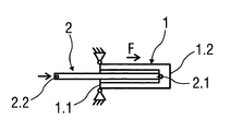
- FIG. 1 shows an untriggered airbag 1 having a traction element 2 or catch strap as a device for moving a mass, which is not depicted in more detail.
- the airbag 1 having the traction element 2 is arranged in or on a vehicle not depicted in more detail.
- the mass to be moved is a vehicle part, for example a car hood, which is able to be raised on an edge facing the windscreen to protect a person colliding with the car hood and is able to be shifted in the direction of the windscreen.
- the airbag 1 having the traction element 2 can be a component of an passenger protection device or a different protection device of the vehicle.
- the airbag 1 is formed hollow-cylindrically in the untriggered state, as is shown in more detail in a perspective view in FIG. 2 , and with its end 1 . 1 arranged fixedly on a vehicle part that is not the mass to be moved.
- the airbag 1 is fluidically coupled with a gas generator not depicted in more detail, the generator in turn being coupled with a control unit, in particular an airbag control device.
- the traction element 2 is fixed by its first end 2 . 1 in the region of an end 1 . 2 opposite the one end 1 . 1 .
- the traction element 2 is fixed to the airbag 1 in such a way that the traction element 2 , depending on its length, is located in sections in the triggered state of the airbag 1 within the hollow space, as is presented in more detail in FIG. 3 .
- the mass to be moved is fixed on an opposite second end 2 . 2 of the traction element 2 .
- the airbag 1 is fixed by the one end 1 . 1 on a vehicle body and the mass to be moved in the shape of the car hood is fixed to the traction element 2 .
- a control signal is produced by the control unit and supplied to the gas generator for activation.
- the gas generator is triggered, wherein a pyrotechnical propellant is ignited, whereby gas is released and supplied to the airbag 1 .
- the airbag 1 is able to be filled by means of the gas, such that it unfolds.
- the airbag 1 is arranged with one end 1 . 1 fixed to the vehicle, such that the airbag 1 unfolds in the direction of its opposite end 1 . 2 , so away from the vehicle part and relative to the first end 1 . 1 .
- Traction F is exerted on the traction element 2 by unfolding in the longitudinal direction of the airbag 1 , such that this is pulled on and the mass to be moved, for example the car hood, is pulled in the direction of the airbag 1 .
- a route that the mass to be moved covers corresponds substantially to a longitudinal expansion of the airbag 1 .
- the airbag 1 has a sealable air vent opening 1 . 3 on its opposite end 1 . 2 .
- a sealing element 3 is fixed to the first end 2 . 1 of the traction element 2 , wherein the traction exerted on the traction element 2 when the airbag 1 unfolds is used for ventilation.
- the sealing element 3 seals the air vent opening 1 . 3 . If the traction reduces, the sealing element 3 is no longer adjacent to the opposite end 1 . 2 , such that the air vent opening 1 . 3 is opened.
- FIG. 4 An enlarged cut-out of the airbag 1 with opened air vent opening 1 . 3 is shown in FIG. 4 and the air vent opening 1 . 3 is sealed by the adjacent sealing element 3 in an alternative embodiment in FIG. 5 .
- FIG. 6 shows the enlarged cut-out with opened air vent opening 1 . 3 and the sealing element 3 fixed to the traction element 2 in the alternative embodiment.
- FIG. 7 is a highly schematic illustration of a vehicle having a vehicle body, a hood and a gas generator.
- vehicle 700 has a vehicle body 702 , a hood 704 , and a gas generator 706 .
- the vehicle 700 also has a device to least for moving the hood 704 .
- the device comprises a hollow, cylindrical airbag 708 fluidically coupled to the gas generator 706 .
- the airbag 708 is fixedly arranged with one end on the vehicle body 702 .
- the device also comprises a traction element 710 fixed in a region of an opposite end of the airbag 708 .
- the hood 704 is fixed to the traction element 710 . When the airbag 708 unfolds, traction is exerted on the traction element 710 in such a way that the hood 704 is moved.
Landscapes
- Engineering & Computer Science (AREA)
- Mechanical Engineering (AREA)
- Air Bags (AREA)
- Superstructure Of Vehicle (AREA)
Abstract
Description
Claims (3)
Applications Claiming Priority (4)
| Application Number | Priority Date | Filing Date | Title |
|---|---|---|---|
| DE102014011013 | 2014-07-24 | ||
| DE102014011013.3A DE102014011013B4 (en) | 2014-07-24 | 2014-07-24 | Device at least for moving a mass and vehicle |
| DE102014011013.3 | 2014-07-24 | ||
| PCT/EP2015/001274 WO2016012071A1 (en) | 2014-07-24 | 2015-06-24 | Device at least for moving a mass, and vehicle having such a device |
Publications (2)
| Publication Number | Publication Date |
|---|---|
| US20170210335A1 US20170210335A1 (en) | 2017-07-27 |
| US10377338B2 true US10377338B2 (en) | 2019-08-13 |
Family
ID=52010545
Family Applications (1)
| Application Number | Title | Priority Date | Filing Date |
|---|---|---|---|
| US15/328,164 Active 2035-12-13 US10377338B2 (en) | 2014-07-24 | 2015-06-24 | Device at least for moving a mass, and vehicle having such a device |
Country Status (6)
| Country | Link |
|---|---|
| US (1) | US10377338B2 (en) |
| EP (1) | EP3172090A1 (en) |
| JP (1) | JP2017521314A (en) |
| CN (1) | CN106573595B (en) |
| DE (1) | DE102014011013B4 (en) |
| WO (1) | WO2016012071A1 (en) |
Families Citing this family (6)
| Publication number | Priority date | Publication date | Assignee | Title |
|---|---|---|---|---|
| KR102195362B1 (en) * | 2014-08-14 | 2020-12-24 | 현대모비스 주식회사 | Airbag Of Vehicle |
| DE102016012084A1 (en) | 2016-10-08 | 2017-10-05 | Daimler Ag | Occupant protection device and vehicle |
| DE102016012083A1 (en) | 2016-10-08 | 2017-10-05 | Daimler Ag | Occupant protection device and vehicle |
| DE102016012106A1 (en) | 2016-10-08 | 2017-10-05 | Daimler Ag | Occupant protection device and vehicle |
| DE102016012075A1 (en) | 2016-10-08 | 2017-09-14 | Daimler Ag | Occupant protection device and vehicle |
| DE102016012085A1 (en) | 2016-10-08 | 2017-09-14 | Daimler Ag | Occupant protection device and vehicle |
Citations (11)
| Publication number | Priority date | Publication date | Assignee | Title |
|---|---|---|---|---|
| JPS62266207A (en) | 1986-05-12 | 1987-11-19 | Tokyo Keiki Co Ltd | Fluid pressure actuator |
| DE4442543A1 (en) | 1994-11-30 | 1996-01-25 | Daimler Benz Ag | Air=bag unit for vehicle |
| US5997037A (en) * | 1997-09-22 | 1999-12-07 | Trw Vehicle Safety Systems Inc. | Air bag with tether |
| CN1446718A (en) | 2002-03-26 | 2003-10-08 | 高田株式会社 | Protective bag device for pedestrian |
| DE10239933A1 (en) | 2002-08-30 | 2004-03-18 | Daimlerchrysler Ag | Impact protection device for motor vehicle has variable volume chamber for impact-type force applications, and damping bellows installed between force application means and structure of vehicle |
| DE202004014928U1 (en) | 2004-09-24 | 2004-12-02 | Festo Ag & Co | Vehicle fitted with pedestrian safety device arranged to lift the bonnet to increase the distance it can deform on impact relative to the chassis and where the gap between the bonnet and the chassis is sealed by a cover |
| DE10353448B3 (en) | 2003-11-15 | 2005-06-23 | Benteler Automobiltechnik Gmbh | B-pillar device for motor vehicle bodywork has at least one optical detector to monitor obstacles in height region above initial position of longitudinal strip |
| CN1931638A (en) | 2005-09-16 | 2007-03-21 | 比亚迪股份有限公司 | Vehicle with pedestrian protecting mechanism |
| US20090001698A1 (en) * | 2007-06-26 | 2009-01-01 | Kyong Cheol Kim | Pressure control apparatus of air bag |
| WO2014032999A1 (en) | 2012-09-03 | 2014-03-06 | Bayerische Motoren Werke Aktiengesellschaft | Safety device for a motor vehicle |
| US20150375711A1 (en) * | 2014-06-30 | 2015-12-31 | Nihon Plast Co., Ltd. | Airbag and airbag device |
-
2014
- 2014-07-24 DE DE102014011013.3A patent/DE102014011013B4/en active Active
-
2015
- 2015-06-24 US US15/328,164 patent/US10377338B2/en active Active
- 2015-06-24 EP EP15731254.7A patent/EP3172090A1/en not_active Withdrawn
- 2015-06-24 CN CN201580040917.7A patent/CN106573595B/en active Active
- 2015-06-24 JP JP2017501404A patent/JP2017521314A/en active Pending
- 2015-06-24 WO PCT/EP2015/001274 patent/WO2016012071A1/en not_active Ceased
Patent Citations (12)
| Publication number | Priority date | Publication date | Assignee | Title |
|---|---|---|---|---|
| JPS62266207A (en) | 1986-05-12 | 1987-11-19 | Tokyo Keiki Co Ltd | Fluid pressure actuator |
| DE4442543A1 (en) | 1994-11-30 | 1996-01-25 | Daimler Benz Ag | Air=bag unit for vehicle |
| US5997037A (en) * | 1997-09-22 | 1999-12-07 | Trw Vehicle Safety Systems Inc. | Air bag with tether |
| CN1446718A (en) | 2002-03-26 | 2003-10-08 | 高田株式会社 | Protective bag device for pedestrian |
| US7025164B2 (en) | 2002-03-26 | 2006-04-11 | Takata Corporation | Protective bag device for pedestrian and the like |
| DE10239933A1 (en) | 2002-08-30 | 2004-03-18 | Daimlerchrysler Ag | Impact protection device for motor vehicle has variable volume chamber for impact-type force applications, and damping bellows installed between force application means and structure of vehicle |
| DE10353448B3 (en) | 2003-11-15 | 2005-06-23 | Benteler Automobiltechnik Gmbh | B-pillar device for motor vehicle bodywork has at least one optical detector to monitor obstacles in height region above initial position of longitudinal strip |
| DE202004014928U1 (en) | 2004-09-24 | 2004-12-02 | Festo Ag & Co | Vehicle fitted with pedestrian safety device arranged to lift the bonnet to increase the distance it can deform on impact relative to the chassis and where the gap between the bonnet and the chassis is sealed by a cover |
| CN1931638A (en) | 2005-09-16 | 2007-03-21 | 比亚迪股份有限公司 | Vehicle with pedestrian protecting mechanism |
| US20090001698A1 (en) * | 2007-06-26 | 2009-01-01 | Kyong Cheol Kim | Pressure control apparatus of air bag |
| WO2014032999A1 (en) | 2012-09-03 | 2014-03-06 | Bayerische Motoren Werke Aktiengesellschaft | Safety device for a motor vehicle |
| US20150375711A1 (en) * | 2014-06-30 | 2015-12-31 | Nihon Plast Co., Ltd. | Airbag and airbag device |
Non-Patent Citations (5)
| Title |
|---|
| Examination Report dated Sep. 13, 2017 in related EP Application No. 15 731 254.7 (reference DE 103 53 448 was previously cited in an IDS on Jul. 25, 2017). |
| International Search Report dated Oct. 29, 2015 in related International Application No. PCT/EP2015/001274. |
| Office Action dated Apr. 26, 2018 in related CN Application No. 201580040917.7. |
| Office Action dated Jul. 7, 2017 in related DE Application No. 10 2014 011 013.3. |
| Written Opinion dated Oct. 29, 2015 in related International Application No. PCT/EP2015/001274. |
Also Published As
| Publication number | Publication date |
|---|---|
| DE102014011013B4 (en) | 2018-03-15 |
| JP2017521314A (en) | 2017-08-03 |
| US20170210335A1 (en) | 2017-07-27 |
| EP3172090A1 (en) | 2017-05-31 |
| CN106573595A (en) | 2017-04-19 |
| CN106573595B (en) | 2020-09-01 |
| WO2016012071A1 (en) | 2016-01-28 |
| DE102014011013A1 (en) | 2014-12-24 |
Similar Documents
| Publication | Publication Date | Title |
|---|---|---|
| US10377338B2 (en) | Device at least for moving a mass, and vehicle having such a device | |
| US10744971B2 (en) | Roof airbag apparatus | |
| US9266495B2 (en) | Dual chamber airbag system | |
| US9988011B2 (en) | Vehicle having a pedestrian protection system | |
| US9457762B2 (en) | Active hood front cover for pedestrian protection | |
| US8596681B1 (en) | Internal deployable vehicle panel assembly | |
| US9566940B2 (en) | External airbag | |
| JP6063976B2 (en) | Outside air bag | |
| KR101500232B1 (en) | Cushion for pedestrian air-bag | |
| US10710544B2 (en) | External airbag | |
| AU2015221501A1 (en) | Device for protection of pedestrians in case of impact with a vehicle | |
| US9067566B1 (en) | Active bolster for pedestrian protection | |
| CN105365738A (en) | Inflatable protection mechanisms for vehicle instrument panel | |
| KR101360437B1 (en) | Air bag cushion module for curtain air bag device | |
| US20190256034A1 (en) | Air bag apparatus | |
| KR102263721B1 (en) | Passenger Airbag Aparatus Of Vehicle | |
| JP7112870B2 (en) | vehicle occupant protection | |
| KR102505743B1 (en) | Air-bag device | |
| JP6593301B2 (en) | Rear structure of the passenger compartment | |
| JP2008195190A (en) | Vehicular airbag device | |
| KR100666624B1 (en) | Curtain airbag | |
| JP7053888B2 (en) | Airbag device | |
| US20150321623A1 (en) | Protection shield for vehicle headliner | |
| EP2801499B1 (en) | Vehicle airbag system for protecting pedestrians and cyclists | |
| JP2018016254A (en) | Vehicle structure |
Legal Events
| Date | Code | Title | Description |
|---|---|---|---|
| AS | Assignment |
Owner name: DAIMLER AG, GERMANY Free format text: ASSIGNMENT OF ASSIGNORS INTEREST;ASSIGNOR:HEINRICH, TILL;REEL/FRAME:041046/0477 Effective date: 20161219 |
|
| STPP | Information on status: patent application and granting procedure in general |
Free format text: NON FINAL ACTION MAILED |
|
| STPP | Information on status: patent application and granting procedure in general |
Free format text: RESPONSE TO NON-FINAL OFFICE ACTION ENTERED AND FORWARDED TO EXAMINER |
|
| STPP | Information on status: patent application and granting procedure in general |
Free format text: FINAL REJECTION MAILED |
|
| STPP | Information on status: patent application and granting procedure in general |
Free format text: NOTICE OF ALLOWANCE MAILED -- APPLICATION RECEIVED IN OFFICE OF PUBLICATIONS |
|
| STCF | Information on status: patent grant |
Free format text: PATENTED CASE |
|
| MAFP | Maintenance fee payment |
Free format text: PAYMENT OF MAINTENANCE FEE, 4TH YEAR, LARGE ENTITY (ORIGINAL EVENT CODE: M1551); ENTITY STATUS OF PATENT OWNER: LARGE ENTITY Year of fee payment: 4 |
|
| AS | Assignment |
Owner name: MERCEDES BENZ GROUP AG, GERMANY Free format text: CHANGE OF NAME;ASSIGNOR:DAIMLER AG;REEL/FRAME:072886/0467 Effective date: 20211001 |