US1037262A - Marble-gun. - Google Patents
Marble-gun. Download PDFInfo
- Publication number
- US1037262A US1037262A US66063011A US1911660630A US1037262A US 1037262 A US1037262 A US 1037262A US 66063011 A US66063011 A US 66063011A US 1911660630 A US1911660630 A US 1911660630A US 1037262 A US1037262 A US 1037262A
- Authority
- US
- United States
- Prior art keywords
- conduit
- gun
- sighting
- marble
- standards
- Prior art date
- Legal status (The legal status is an assumption and is not a legal conclusion. Google has not performed a legal analysis and makes no representation as to the accuracy of the status listed.)
- Expired - Lifetime
Links
- 210000003414 extremity Anatomy 0.000 description 8
- 238000010276 construction Methods 0.000 description 2
- 241000260460 Buteogallus Species 0.000 description 1
- JFLRKDZMHNBDQS-UCQUSYKYSA-N CC[C@H]1CCC[C@@H]([C@H](C(=O)C2=C[C@H]3[C@@H]4C[C@@H](C[C@H]4C(=C[C@H]3[C@@H]2CC(=O)O1)C)O[C@H]5[C@@H]([C@@H]([C@H]([C@@H](O5)C)OC)OC)OC)C)O[C@H]6CC[C@@H]([C@H](O6)C)N(C)C.CC[C@H]1CCC[C@@H]([C@H](C(=O)C2=C[C@H]3[C@@H]4C[C@@H](C[C@H]4C=C[C@H]3C2CC(=O)O1)O[C@H]5[C@@H]([C@@H]([C@H]([C@@H](O5)C)OC)OC)OC)C)O[C@H]6CC[C@@H]([C@H](O6)C)N(C)C Chemical compound CC[C@H]1CCC[C@@H]([C@H](C(=O)C2=C[C@H]3[C@@H]4C[C@@H](C[C@H]4C(=C[C@H]3[C@@H]2CC(=O)O1)C)O[C@H]5[C@@H]([C@@H]([C@H]([C@@H](O5)C)OC)OC)OC)C)O[C@H]6CC[C@@H]([C@H](O6)C)N(C)C.CC[C@H]1CCC[C@@H]([C@H](C(=O)C2=C[C@H]3[C@@H]4C[C@@H](C[C@H]4C=C[C@H]3C2CC(=O)O1)O[C@H]5[C@@H]([C@@H]([C@H]([C@@H](O5)C)OC)OC)OC)C)O[C@H]6CC[C@@H]([C@H](O6)C)N(C)C JFLRKDZMHNBDQS-UCQUSYKYSA-N 0.000 description 1
- 238000006730 Kennedy cyclization reaction Methods 0.000 description 1
- 241001421775 Thereus Species 0.000 description 1
- 210000003141 lower extremity Anatomy 0.000 description 1
- 239000004579 marble Substances 0.000 description 1
- 239000002184 metal Substances 0.000 description 1
- 238000000034 method Methods 0.000 description 1
- YNPFMWCWRVTGKJ-UHFFFAOYSA-N mianserin hydrochloride Chemical compound [H+].[Cl-].C1C2=CC=CC=C2N2CCN(C)CC2C2=CC=CC=C21 YNPFMWCWRVTGKJ-UHFFFAOYSA-N 0.000 description 1
- 238000009877 rendering Methods 0.000 description 1
- 239000007787 solid Substances 0.000 description 1
Images

Classifications
-
- F—MECHANICAL ENGINEERING; LIGHTING; HEATING; WEAPONS; BLASTING
- F41—WEAPONS
- F41B—WEAPONS FOR PROJECTING MISSILES WITHOUT USE OF EXPLOSIVE OR COMBUSTIBLE PROPELLANT CHARGE; WEAPONS NOT OTHERWISE PROVIDED FOR
- F41B7/00—Spring guns
Definitions
- My invention relates to improvements in marble-guns, and the objects of my improvements are these: first, to provide a marble-gun with means for correctly sighting it; second, to render such sightingmeans foldable over upon the gun to per mit the whole to be easily carried in the pocket; third, to adapt the rear sighting means to act as a discharge trigger as well as engaging detachably the propelling means; fourth, to furnish movable pointers on the sighting-means to assist inlocating the object aimed at; fifth, to modify the form of the gun to permit it to be seated ina stable position upon the ground, and sixth, to adapt the gun and its said sighting-means to each other so as to permit the sights to fold over upon the gun toward each other, while being prevented from moving in opposite directions beyond the vertical.
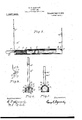
- Figure 1 is a longitudinal vertical central? is a rear elevation of. the rear sighting. means, and Fig.3 is a rear elevation of the" forward sighting-means taken one trans versesection of the gun body.
- Fig. 4' is a horizontal transverse section of the rear sighting-means taken on a line 3l of Fig. 2.
- Fig. 5 is a longitudinal vertical central section through the marble-gun of amodified construction, with the sighting-means shown in both full and dotted lines as in Fig. 1, the propelling-means set for discharge.
- Fig. 6 is a rear elevation of the rear sighting-means of the gun shown in Fig. 5
- Fig. 7- is a front elevation of the forward sighting means thereof.
- FIG. 8 is a detailed view of one of the rear coriiersof the gun-conduit, showing the method whereby the side standard of the sightingmeans is adapted to seat itself thereon to hold such means in either an erect or forwardly-prostrate condition.
- the gun-body is a tube formed from a suitably shaped metallic blank which is bent over and its longitudinal edges in its middle portion united to produce a hollow cylindrical conduit adapted to receive marbles Z.
- the forward part b and the rear part c of said blank are not united at their longitudinal edges, but by means of a cut in each extending part wa) from their edges toward the middle line, the blank may be formed into a squared body at each end with vertical walls on each side, the squared bases of these parts 6 and 0 being thus adapted to be in line in the same horizontal plane and therefore provide a secure and stable seat for the gun on the ground or other flat surface.
- a coiled compression-spring t Located partly within the gun-bore and partly in the squared rear channel 0 is a coiled compression-spring t, to whose forward end is secured a cylindrical solid head within the gun-bore a. Extending rearwardly from the head 71 and secured to it by a nail s, and within the hollow of said spring, is a rod p which has a finger-piece F72 and its upper edge is provided with a number of forwardly directed teeth 7'.
- the rear sight comprises a plate (Z having a medial longitudinal slot (Z and a movable pointer c is slidably seated in said slot, the
- pointer being formed of, a single small piece of metal bent to embrace the edges of the slot.
- the forward sight in is similarly formed but'shorter, and has a similar slot on and slidable pointer n.
- the forward sight 1/?- is pivoted to the for ward part or corners of the part Z) above the line of the gun-bore, on a pintle 2.
- the part to which this sight is pivoted is projected above the upper edge of the part b on each side to form a raised part having a rearwardly-curved edge 7), over which laterallyproject'ed wings of thesight m move with a close-fitting contact. Since the forward part of said projection is angular, the sight when raised to a vertical position, cannot move forwardly from said position, though it may be swung rearwardly to a prostrate position along the gun ll as indicated by the dotted lines in Fig. l.
- the rear sight 11 is similarly mounted with like lateral wings which engage a.
- the rear sight (l has its lower end divided to form a deep groove (1 therein, and the divided members thus formed are curved forwardly and pivoted on a pintle 1 to the sides of the part 0, said pintle also serving as a means of attachment and fulcrum for the rear end of the spring t.
- the inner transverse edge of the groove (1 in said sight is far enough from the pintle q to permit the teeth r of the rod p to be engaged by it when the sight is brought to its vertical position as shown in Fig. 1.
- the curving of the lower end of the sight changes the relations thereof relative to the rod-teeth r so that when the sight (Z is swung forward a little the teeth r become disengaged from said sight, which thus becomes a trigger with relation to said rod and spring.
- the sight (Z when the rod is drawn forward as much as desired, the sight (Z may be swung to a vertical position engaging the teeth '2, and may be held in that position until the aim has been adjusted, when the spring t may beinstantaneously released by merely swinging forward the sight (1 slightly.
- the plurality of teeth 7* on said rod 7) permits a number of adjustments of the tension of said spring to be made according to the distance necessary to cast the marble Z. ⁇ Vhen both sights have been lowered, the compass of the whole gun is small, and it may be easily carried in the pocket of the owner, while if desired, a ring j may be slid over the parts to keep them in place.
- the device illustrated in Figs. 5 to 8 inclusive employs the same principles of operation generally, but with somewhatvaried details of construction.
- the same gun-body a, spring 2%, head k are used, but the rod p is formed of a resilient or yieldable rod which is bent upon itself to form a closed loop, the forward end 7" of the loop being made angular in order to permit it to engage the lower part of the sighting-device d at the rear when the latter is erected to the position shown in Fig. 5, and when the spring has been put under tension.
- the forward sight m is formed of a loop of wire, about which is slidably seated a looped pointer 01/.
- the lower ends of the members w and a: of the loop m are bent to cross each other, and their extremities are then bent outwardly to pass through orifices in the parts 7), then bent toward the plane of the loop m and then bent back to cross the vertical edges of the parts 5 when the loop at is erect.
- the angles of the parts I) are curved on the arc of a circle whose radius is the distance from the bearing-orifice in the part b to the contacting edge of said curved edge with the part crossing it, and the crossed part fits said curved edge closely with rubbing contact.
- the rear sighting-means d is of similar form to the one just described, and its crossed lower extremities similarly engage curved angles of the rear part c, and drop into locking notches h and i when either lowered or raised.
- the rear sight (2 has a similar slidable pointer e.
- the crossed extremities u and o of the rear sight are crossed almost horizontally to provide engaging means for the angle 1' of the rod p, and the ends'of these extremities f similarly bind in moving over the curved angles of the parts 0.
- the rod 79 may be yieldingly bent downward sufliciently to clear the crossed extremities u and o of the rear sight d, and thus the spring t is discharged.
- a conduit in combination, a conduit, an erect sighting-device on said conduit, and propelling-means located at one end of said conduit, said conduit having catches adapted to engage with said sighting-device to detachably secure it in either an erect or a recumbent position.
- a conduit in combination, a conduit, an erect sighting-device on each end thereof, and propelling-means located at one end of said conduit, said sighting-devices being adapted to swing in one direction only to move toward each other, said conduit and said sighting-devices having co-acting catches adapted to detachably cooperate for detachably securing said devices to said conduit when the former are prostrated thereupon.
- conduit, and sighting-standards pivoted on its ends in the medial line thereof, said conduit having catches thereon for detachably securing said standards thereto when swung over thereupon.
- a conduit cylindrical in its middle portion and having squared ends with open tops, sighting-standards pivoted to the walls of said open ends, said standards engaging said conduit to prevent movement from the vertical in one direction, but each being adapted to swing toward each other to lieupon the conduit.
- a cylindrical conduit having its ends squared and open at the top, sighting-standards pivoted to the walls of said squared ends and engaging same toprevent movement away from said conduit outwardly, said standards being adapted to fold upon each other and upon the conduit, a driving-head movably seated in said conduit, a spring connected to said driving-head, a rod connected to said driving-head and adapted to be shifted to place said spring under tension, said rod and the rearmost of said standards being adapted to be engaged, with each other and then released from each other to secure said spring under tension and then discharge it therefrom.
- a conduit having its ends notched, and sighting-standards connected to the ends thereof and adapted to be moved toward the conduit to be recumbent thereon and to engage said notches detachably when in that po* sition.
- a conduit, sighting-standards pivoted to the ends thereof and adapted to be swung over thereu on, a driving-head movably seated in said conduit, a spring connected to'said driving-head, a finger-piece connected to said driving-head and adapted to be shifted to place said spring. under tension, said finger-piece and the rearmost of said sighting'standards being adapted to be engaged together detachaoly when said spring 18 under tension.
- a conduit having its base formed to stand stablv on a fiat surface, sightingstandards movably connected to the ends thereof and adapted to be moved recumbently thereon from an erect position, a driving-head movably seated in said conduit, a spring connected to said driving-head, a finger-piece connected to said driving-head and adapted to be shifted to place said spring under tension, said finger-piece and the rearmost of said sighting-standards being adapted to be detachably engaged when said'spring has been placed under tension.
- a conduit having portions of its base formed to rest stably on a plane surface, sightingstandards pivoted to the ends of said conduits and having means to prevent their being deflected away from each other beyond vertical lines, a driving-head movably seated in said conduit, a spring operatively connected therewith, a finger-piece connected to said head and having a plurality of engaging-means thereon, the rearmost of said sighting-standards being formed to be engaged with the engaging-means adjustably on said finger-piece when the said spring has been placed under tension to a desired degree and the standard brought to a vertical position.
- a conduit and a sighting-standard foldably connected thereto the said standard and conduit having engaging-means co-engaging when the standard is in an erect position to detachablv rigidly hold it in that position.
- a conduit having resilient propelling-means therein and connected thereto, means for placing said propelling-means under tension, and a sighting-standard on said conduit adapted to be engaged with said propelling-means when the latter under tension and to become disengaged therefrom to discharge such means when moved in a certain direction.
- a conduit and sighting-standards pivoted thereto near each end, the said standards and conduit; having engaging-means co-engaging when the standards are in either an erect or recumbent position, to detachably secure them in those positions.
- a conduit and sighting-standards pivoted thereto near each end and having projections adapted to detachably (o-engage therewith in either an erect or a recumbent position on the conduit, and to be prevented from moving away from each other beyond the erect position when so co-engaged.
- a conduit, yieldable resilient propellingmeans connected to said conduit and movable thereint'o.
- a signing-standard pivoted to said conduit near said propelling-means and adapted to be detachably engaged with said propelling-means when the latter is in an adjusted state of tension, said standard being adapted to release itself from said propelling-means and discharge the latter when swung forwardly, and said standard being adapted to engage said conduit to engage therewith to prevent its moving rearwardly beyond a vertical position.
- a conduit. and sighting-standards pivoted within its ends and adapted to fold toward each other to a recumbent position on said conduit, said standard having lateral pro-.
- jections adapted to enter into fri tional en gagement with the conduit to secure them in a certain position relative thereto.
- a conduit formed from a single plate whose middle part is bent over and the edges united in a cylindrical shape with the ends left open at the top and squared to have tlat bottoms at the ends and erect side walls, and sighting-standards having their lower ends pivotally connected to the side-walls of said open ends, and adapted to be swung over to lie recumbent upon the cylindrical part of the conduit.
- a conduit formed from a single plate whose middle part is bent over and the edges united in a cylindrical shape with the ends left open at the top and squared to have fiat bottoms at the ends and erect side walls, and yieldable resilient propelling-means within said conduit and connected thereto.
Landscapes
- Engineering & Computer Science (AREA)
- General Engineering & Computer Science (AREA)
- Footwear And Its Accessory, Manufacturing Method And Apparatuses (AREA)
Description
G. G. KENNEDY.
MARBLE GUN.
APPLICATION FILED NOV. 16 1911.
1,037,262. Patented Sept. 3, 1912,
. 2 sums-sum 1.
Fig. 1. P
witnesses: Inventor.
APPLICATION FILED NOV. 16, 1911.
1,037,262. Patented Sept. 3,1912.
I 2 SHBET-BHEETI z.
Fig.5.
wgltnsszsi l'nyzntor,
ono'ncn'oonvm KENNEDY, or WATERLOO, IOWA.
MARBLE-GUN. 1
Specification of Letters Patent.
Patented Sept. 3, 1912.
Application filed November 16, 1911. Serial No. 660,630.
T a1 Z whom it may concern Be it known that I, GEORGE Convm KEN- NEDY, a citizen of the United States of America, and a; resident of Waterloo, Blackhawk county, Iowa, have invented certain new and useful Improvements in Marble- Guns,-of which the following is a specification.
My invention relates to improvements in marble-guns, and the objects of my improvements are these: first, to provide a marble-gun with means for correctly sighting it; second, to render such sightingmeans foldable over upon the gun to per mit the whole to be easily carried in the pocket; third, to adapt the rear sighting means to act as a discharge trigger as well as engaging detachably the propelling means; fourth, to furnish movable pointers on the sighting-means to assist inlocating the object aimed at; fifth, to modify the form of the gun to permit it to be seated ina stable position upon the ground, and sixth, to adapt the gun and its said sighting-means to each other so as to permit the sights to fold over upon the gun toward each other, while being prevented from moving in opposite directions beyond the vertical. These objects I have accomplished by the means which are hereinafter described and claimed, and which are illus trated in the accompanying drawings, in which:
Figure 1 is a longitudinal vertical central? is a rear elevation of. the rear sighting. means, and Fig.3 is a rear elevation of the" forward sighting-means taken one trans versesection of the gun body.- Fig. 4' is a horizontal transverse section of the rear sighting-means taken on a line 3l of Fig. 2. Fig. 5 is a longitudinal vertical central section through the marble-gun of amodified construction, with the sighting-means shown in both full and dotted lines as in Fig. 1, the propelling-means set for discharge. Fig. 6 is a rear elevation of the rear sighting-means of the gun shown in Fig. 5, and Fig. 7- is a front elevation of the forward sighting means thereof. Fig. 8 is a detailed view of one of the rear coriiersof the gun-conduit, showing the method whereby the side standard of the sightingmeans is adapted to seat itself thereon to hold such means in either an erect or forwardly-prostrate condition.
Similar characters of reference designate corresponding parts throughout the several news.
The gun-body is a tube formed from a suitably shaped metallic blank which is bent over and its longitudinal edges in its middle portion united to produce a hollow cylindrical conduit adapted to receive marbles Z. The forward part b and the rear part c of said blank are not united at their longitudinal edges, but by means of a cut in each extending part wa) from their edges toward the middle line, the blank may be formed into a squared body at each end with vertical walls on each side, the squared bases of these parts 6 and 0 being thus adapted to be in line in the same horizontal plane and therefore provide a secure and stable seat for the gun on the ground or other flat surface.
Located partly within the gun-bore and partly in the squared rear channel 0 is a coiled compression-spring t, to whose forward end is secured a cylindrical solid head within the gun-bore a. Extending rearwardly from the head 71 and secured to it by a nail s, and within the hollow of said spring, is a rod p which has a finger-piece F72 and its upper edge is provided with a number of forwardly directed teeth 7'.
On the ends of the parts 6 and c are located the sighting-means d and m, alined in the middle longitudinal line of the gun. The rear sight comprises a plate (Z having a medial longitudinal slot (Z and a movable pointer c is slidably seated in said slot, the
pointer being formed of, a single small piece of metal bent to embrace the edges of the slot. The forward sight in is similarly formed but'shorter, and has a similar slot on and slidable pointer n.
The forward sight 1/?- is pivoted to the for ward part or corners of the part Z) above the line of the gun-bore, on a pintle 2. The part to which this sight is pivoted is projected above the upper edge of the part b on each side to form a raised part having a rearwardly-curved edge 7), over which laterallyproject'ed wings of thesight m move with a close-fitting contact. Since the forward part of said projection is angular, the sight when raised to a vertical position, cannot move forwardly from said position, though it may be swung rearwardly to a prostrate position along the gun ll as indicated by the dotted lines in Fig. l. The rear sight 11 is similarly mounted with like lateral wings which engage a. similar projection 0 on each. side, the projection serving to permit forward but not rearward swinging of the sight- The rear sight (l has its lower end divided to form a deep groove (1 therein, and the divided members thus formed are curved forwardly and pivoted on a pintle 1 to the sides of the part 0, said pintle also serving as a means of attachment and fulcrum for the rear end of the spring t. The inner transverse edge of the groove (1 in said sight is far enough from the pintle q to permit the teeth r of the rod p to be engaged by it when the sight is brought to its vertical position as shown in Fig. 1. However, the curving of the lower end of the sight changes the relations thereof relative to the rod-teeth r so that when the sight (Z is swung forward a little the teeth r become disengaged from said sight, which thus becomes a trigger with relation to said rod and spring. In other words, when the rod is drawn forward as much as desired, the sight (Z may be swung to a vertical position engaging the teeth '2, and may be held in that position until the aim has been adjusted, when the spring t may beinstantaneously released by merely swinging forward the sight (1 slightly. The plurality of teeth 7* on said rod 7) permits a number of adjustments of the tension of said spring to be made according to the distance necessary to cast the marble Z. \Vhen both sights have been lowered, the compass of the whole gun is small, and it may be easily carried in the pocket of the owner, while if desired, a ring j may be slid over the parts to keep them in place.
The device illustrated in Figs. 5 to 8 inclusive employs the same principles of operation generally, but with somewhatvaried details of construction. The same gun-body a, spring 2%, head k are used, but the rod p is formed of a resilient or yieldable rod which is bent upon itself to form a closed loop, the forward end 7" of the loop being made angular in order to permit it to engage the lower part of the sighting-device d at the rear when the latter is erected to the position shown in Fig. 5, and when the spring has been put under tension. The forward sight m is formed of a loop of wire, about which is slidably seated a looped pointer 01/. The lower ends of the members w and a: of the loop m are bent to cross each other, and their extremities are then bent outwardly to pass through orifices in the parts 7), then bent toward the plane of the loop m and then bent back to cross the vertical edges of the parts 5 when the loop at is erect. The angles of the parts I) are curved on the arc of a circle whose radius is the distance from the bearing-orifice in the part b to the contacting edge of said curved edge with the part crossing it, and the crossed part fits said curved edge closely with rubbing contact. ()n the-upper and vertical edges of said parts Z) are the notches 3 and 0 respectively, and the crossed parts of said looped extremities tend to drop thereinto when in the erect or prostrate position of the forward sight, as indicated in Fig. 5, the springiness of the member tending in each case to retain it in the notch in which it. may have been placed. For obvious reasons, the engagement is such, that the part on cannot be displaced forwardly from the vertical posit-ion, but it may be easily disengaged from the notch and then brought down to the prostrate position, in which last position it tends to be held by the notch y, rendering other retaining-means unnecessary. The rear sighting-means d" is of similar form to the one just described, and its crossed lower extremities similarly engage curved angles of the rear part c, and drop into locking notches h and i when either lowered or raised. The rear sight (2 has a similar slidable pointer e. The crossed extremities u and o of the rear sight are crossed almost horizontally to provide engaging means for the angle 1' of the rod p, and the ends'of these extremities f similarly bind in moving over the curved angles of the parts 0. When the aim is adjusted, the rod 79 may be yieldingly bent downward sufliciently to clear the crossed extremities u and o of the rear sight d, and thus the spring t is discharged.
It is to be understood that slight VZtIlL- tions, or equivalents of the parts described may be adopted in lieu thereof, without departing from the full scope and principles of my invention.
Having described my invention, What I claim as new, and desire to secure by Letters Patent, is:
1. In a marble-gun, in combination, a conduit, an erect sighting-device on said conduit, and propelling-means located at one end of said conduit, said conduit having catches adapted to engage with said sighting-device to detachably secure it in either an erect or a recumbent position.
2. In a marble-gun, in combination, a conduit, an erect sighting-device on each end thereof, and propelling-means located at one end of said conduit, said sighting-devices being adapted to swing in one direction only to move toward each other, said conduit and said sighting-devices having co-acting catches adapted to detachably cooperate for detachably securing said devices to said conduit when the former are prostrated thereupon.
3. In a marble-gun, in combination, a
conduit, and sighting-standards pivoted on its ends in the medial line thereof, said conduit having catches thereon for detachably securing said standards thereto when swung over thereupon.
4. In a marble-gun, in combination, a conduit cylindrical in its middle portion and having squared ends with open tops, sighting-standards pivoted to the walls of said open ends, said standards engaging said conduit to prevent movement from the vertical in one direction, but each being adapted to swing toward each other to lieupon the conduit.
5. In a marble-gun, in combination, a cylindrical conduit having its ends squared and open at the top, sighting-standards pivoted to the walls of said squared ends and engaging same toprevent movement away from said conduit outwardly, said standards being adapted to fold upon each other and upon the conduit, a driving-head movably seated in said conduit, a spring connected to said driving-head, a rod connected to said driving-head and adapted to be shifted to place said spring under tension, said rod and the rearmost of said standards being adapted to be engaged, with each other and then released from each other to secure said spring under tension and then discharge it therefrom.
6. In a marble-gun, in combination, a conduit having sighting-standards pivoted to its extremities in its medial longitudinal line, a driving-head movably seated in said conduit, a spring operatively connected thereto, a rod connected to said driving headand adapted to be; shifted to placeisaid spring under tension, said rod having detents on one edge, and the lower part of the rearmost of said sighting-standards being formed to engage detents on said rod when the latter is shifted to place said spring under tension, and to become released from said detents when it is swung forwardly toward said conduit.
7. In a Inarble-gun, in combination, a conduit having its ends notched, and sighting-standards connected to the ends thereof and adapted to be moved toward the conduit to be recumbent thereon and to engage said notches detachably when in that po* sition. 1 I
8. In a marble-gun, in combination, a conduit, sighting-standards pivoted to the ends thereof and adapted to be swung over thereu on, a driving-head movably seated in said conduit, a spring connected to'said driving-head, a finger-piece connected to said driving-head and adapted to be shifted to place said spring. under tension, said finger-piece and the rearmost of said sighting'standards being adapted to be engaged together detachaoly when said spring 18 under tension.
9. In a marble-gun, in combination, a conduit having its base formed to stand stablv on a fiat surface, sightingstandards movably connected to the ends thereof and adapted to be moved recumbently thereon from an erect position, a driving-head movably seated in said conduit, a spring connected to said driving-head, a finger-piece connected to said driving-head and adapted to be shifted to place said spring under tension, said finger-piece and the rearmost of said sighting-standards being adapted to be detachably engaged when said'spring has been placed under tension.
10. In a marble-gun, in combination, a conduit having portions of its base formed to rest stably on a plane surface, sightingstandards pivoted to the ends of said conduits and having means to prevent their being deflected away from each other beyond vertical lines, a driving-head movably seated in said conduit, a spring operatively connected therewith, a finger-piece connected to said head and having a plurality of engaging-means thereon, the rearmost of said sighting-standards being formed to be engaged with the engaging-means adjustably on said finger-piece when the said spring has been placed under tension to a desired degree and the standard brought to a vertical position.
ll. In a marble-gun, in combination. a conduit having sighting-standards pivoted to its extremities, yieldable resilient propelling-means in said conduit, the lower part of the rearmost sighting-standard being so curved from its pivots as to cause it to engage and hold said propelling means when placed erect and when said means are under tension and to become disengaged therefrom when it is tilted forwardly on its pivots.
12. In a marble-gun, in combination, a conduit and a sighting-standard foldably connected thereto, the said standard and conduit having engaging-means co-engaging when the standard is in an erect position to detachablv rigidly hold it in that position.
13. In a marble-gun, in combination, a conduit and a sightingstandard foldably connected thereto, the said standard and conduit having engaging-means co-engaging when the standard is in a recumbent position to rigidly hold it in that position.
14. In a marble-gun, in combination, a conduit having resilient propelling-means therein and connected thereto, means for placing said propelling-means under tension, and a sighting-standard on said conduit adapted to be engaged with said propelling-means when the latter under tension and to become disengaged therefrom to discharge such means when moved in a certain direction.
15. In a marble-gun, in combination, at I conduit having its extremities formed to support it stably on a flat surface, resilient propelling-means in said conduit and connected thereto, means for placing said propelling-means under an adjustable tension, and a sighting-standard on said conduit adapted to be moved to lie recumbently upon the conduit, said standard having its lower end formed to engage and detachably hold said propelling-means in an adjusted position.
16. In a marble-gun, in combination, a conduit, and a sighting-standard pivoted thereto near one end and having a projection adapted to yieldingly resiliently engage with the end of said conduit when erect to retain the standard detachably in a vertical position.
17. In a marble-gun, in combination, a conduit, and a sighting-standard pivoted thereto near one end and having a projection adapted to yieldingly resiliently engage with said conduit near its endwhen recumbent to retain the standard detachably in a recumbent position upon the conduit.
18. In a marble-gun, in combination, a conduit and sighting-standards pivoted thereto near each end, the said standards and conduit; having engaging-means co-engaging when the standards are in either an erect or recumbent position, to detachably secure them in those positions.
19. In a marble-gun, in combination, a conduit and sighting-standards pivoted thereto near each end and having projections adapted to detachably (o-engage therewith in either an erect or a recumbent position on the conduit, and to be prevented from moving away from each other beyond the erect position when so co-engaged.
20. In a marble-gun, in combination, a conduit, yieldable resilient propellingmeans connected to said conduit and movable thereint'o. a signing-standard pivoted to said conduit near said propelling-means and adapted to be detachably engaged with said propelling-means when the latter is in an adjusted state of tension, said standard being adapted to release itself from said propelling-means and discharge the latter when swung forwardly, and said standard being adapted to engage said conduit to engage therewith to prevent its moving rearwardly beyond a vertical position.
21. In a. marble-gun, in combination, a conduit. and sighting-standards pivoted within its ends and adapted to fold toward each other to a recumbent position on said conduit, said standard having lateral pro-.
jections adapted to enter into fri tional en gagement with the conduit to secure them in a certain position relative thereto.
22. In a marble-gun, in combination, a conduit formed from a single plate whose middle part is bent over and the edges united in a cylindrical shape with the ends left open at the top and squared to have tlat bottoms at the ends and erect side walls, and sighting-standards having their lower ends pivotally connected to the side-walls of said open ends, and adapted to be swung over to lie recumbent upon the cylindrical part of the conduit.
23. In a marble-gun, in combination, a conduit formed from a single plate whose middle part is bent over and the edges united in a cylindrical shape with the ends left open at the top and squared to have fiat bottoms at the ends and erect side walls, and yieldable resilient propelling-means within said conduit and connected thereto.
24. In a marble-gun, in combination, a conduitformed from a single plate whose middle part is bent over and its edges united to form a hollow tube, with its end portions left open at the top and ends, sighting-standards erected upon the ends of said tube, and yieldable resilient propellingmeans operatively contained within said conduit.
25. In a marble-gun, in combination, a conduit and a sighting-standard foldably connected thereto, the said standard and conduit having engaging-means co-engaging when the standard is in an erect posittion to detachably rigidly hold it in that position, and an indicating-device adjustably seated upon said standard.
26. In a marble-gun, in combination, a conduit and sighting-standards foldably connected thereto, the said standards and conduit having engaging-means co-engaging when the standards are in either an erect or in a recumbent position to hold them in either of said positions, and indieating-means movably seated upon said standards.
27. In a marble-gun, in combination, a conduit and a sighting-standard foldably connectedthereto,sai .l standard and conduitv being so formed and adapted as to co-cngage and enter into a detachable rigid or relatively fixed connection when the standard is moved into a certain position relative to the conduit.
Signed at aterloo, Iowa, this 13th day of November, 1911.-
GEORGE (TOLVIN KENNEDY.
\Vitnesses:
IVTRT P. Iloxu-z, V. II. Bnowx.
Priority Applications (1)
| Application Number | Priority Date | Filing Date | Title |
|---|---|---|---|
| US66063011A US1037262A (en) | 1911-11-16 | 1911-11-16 | Marble-gun. |
Applications Claiming Priority (1)
| Application Number | Priority Date | Filing Date | Title |
|---|---|---|---|
| US66063011A US1037262A (en) | 1911-11-16 | 1911-11-16 | Marble-gun. |
Publications (1)
| Publication Number | Publication Date |
|---|---|
| US1037262A true US1037262A (en) | 1912-09-03 |
Family
ID=3105539
Family Applications (1)
| Application Number | Title | Priority Date | Filing Date |
|---|---|---|---|
| US66063011A Expired - Lifetime US1037262A (en) | 1911-11-16 | 1911-11-16 | Marble-gun. |
Country Status (1)
| Country | Link |
|---|---|
| US (1) | US1037262A (en) |
Cited By (1)
| Publication number | Priority date | Publication date | Assignee | Title |
|---|---|---|---|---|
| US3969827A (en) * | 1975-07-11 | 1976-07-20 | The United States Of America As Represented By The Secretary Of The Army | Folding weapon sight |
-
1911
- 1911-11-16 US US66063011A patent/US1037262A/en not_active Expired - Lifetime
Cited By (1)
| Publication number | Priority date | Publication date | Assignee | Title |
|---|---|---|---|---|
| US3969827A (en) * | 1975-07-11 | 1976-07-20 | The United States Of America As Represented By The Secretary Of The Army | Folding weapon sight |
Similar Documents
| Publication | Publication Date | Title |
|---|---|---|
| US3285237A (en) | Laterally displaceable arrow rest | |
| US9372049B2 (en) | Handle sight | |
| US1451732A (en) | Fish-rod holder | |
| US8625211B2 (en) | Variable magnification device and telescopic sight using the same | |
| US1037262A (en) | Marble-gun. | |
| US281338A (en) | Arm-rest | |
| US498070A (en) | Spring-gun | |
| US1053400A (en) | Camera attachment. | |
| US3163697A (en) | Archery bow sight utilizing optical rangefinder and coupled sighting element | |
| US714770A (en) | Toy target and gun apparatus. | |
| US2287636A (en) | Ball gun | |
| US756988A (en) | Toy pistol. | |
| US1419538A (en) | Ball projector | |
| US2083677A (en) | Sight for firearms | |
| US468206A (en) | Territory | |
| US863270A (en) | Apparatus for turning and bowing the heads of dolls. | |
| US1193993A (en) | clarke | |
| US911721A (en) | Gun-sight. | |
| US420261A (en) | John s | |
| US825169A (en) | Instrument for sighting guns from cover. | |
| US1178439A (en) | Finder for cameras. | |
| US1084599A (en) | Toy gun. | |
| US920565A (en) | Toy pistol. | |
| US182330A (en) | Improvement in arrow-guns | |
| US213131A (en) | Improvement in picture-frame attachments |