US10367410B2 - Method and system for identifying power system element parameters and power correction factor - Google Patents
Method and system for identifying power system element parameters and power correction factor Download PDFInfo
- Publication number
- US10367410B2 US10367410B2 US14/914,957 US201414914957A US10367410B2 US 10367410 B2 US10367410 B2 US 10367410B2 US 201414914957 A US201414914957 A US 201414914957A US 10367410 B2 US10367410 B2 US 10367410B2
- Authority
- US
- United States
- Prior art keywords
- power
- circumflex over
- telemetering
- steady state
- node
- Prior art date
- Legal status (The legal status is an assumption and is not a legal conclusion. Google has not performed a legal analysis and makes no representation as to the accuracy of the status listed.)
- Expired - Fee Related, expires
Links
Images


Classifications
-
- H—ELECTRICITY
- H02—GENERATION; CONVERSION OR DISTRIBUTION OF ELECTRIC POWER
- H02M—APPARATUS FOR CONVERSION BETWEEN AC AND AC, BETWEEN AC AND DC, OR BETWEEN DC AND DC, AND FOR USE WITH MAINS OR SIMILAR POWER SUPPLY SYSTEMS; CONVERSION OF DC OR AC INPUT POWER INTO SURGE OUTPUT POWER; CONTROL OR REGULATION THEREOF
- H02M1/00—Details of apparatus for conversion
- H02M1/42—Circuits or arrangements for compensating for or adjusting power factor in converters or inverters
-
- G—PHYSICS
- G01—MEASURING; TESTING
- G01R—MEASURING ELECTRIC VARIABLES; MEASURING MAGNETIC VARIABLES
- G01R19/00—Arrangements for measuring currents or voltages or for indicating presence or sign thereof
- G01R19/25—Arrangements for measuring currents or voltages or for indicating presence or sign thereof using digital measurement techniques
- G01R19/2513—Arrangements for monitoring electric power systems, e.g. power lines or loads; Logging
-
- G—PHYSICS
- G01—MEASURING; TESTING
- G01R—MEASURING ELECTRIC VARIABLES; MEASURING MAGNETIC VARIABLES
- G01R21/00—Arrangements for measuring electric power or power factor
- G01R21/133—Arrangements for measuring electric power or power factor by using digital technique
-
- G—PHYSICS
- G01—MEASURING; TESTING
- G01R—MEASURING ELECTRIC VARIABLES; MEASURING MAGNETIC VARIABLES
- G01R27/00—Arrangements for measuring resistance, reactance, impedance, or electric characteristics derived therefrom
- G01R27/02—Measuring real or complex resistance, reactance, impedance, or other two-pole characteristics derived therefrom, e.g. time constant
- G01R27/16—Measuring impedance of element or network through which a current is passing from another source, e.g. cable, power line
-
- G—PHYSICS
- G01—MEASURING; TESTING
- G01R—MEASURING ELECTRIC VARIABLES; MEASURING MAGNETIC VARIABLES
- G01R31/00—Arrangements for testing electric properties; Arrangements for locating electric faults; Arrangements for electrical testing characterised by what is being tested not provided for elsewhere
- G01R31/40—Testing power supplies
-
- H—ELECTRICITY
- H04—ELECTRIC COMMUNICATION TECHNIQUE
- H04Q—SELECTING
- H04Q9/00—Arrangements in telecontrol or telemetry systems for selectively calling a substation from a main station, in which substation desired apparatus is selected for applying a control signal thereto or for obtaining measured values therefrom
-
- G—PHYSICS
- G06—COMPUTING; CALCULATING OR COUNTING
- G06Q—INFORMATION AND COMMUNICATION TECHNOLOGY [ICT] SPECIALLY ADAPTED FOR ADMINISTRATIVE, COMMERCIAL, FINANCIAL, MANAGERIAL OR SUPERVISORY PURPOSES; SYSTEMS OR METHODS SPECIALLY ADAPTED FOR ADMINISTRATIVE, COMMERCIAL, FINANCIAL, MANAGERIAL OR SUPERVISORY PURPOSES, NOT OTHERWISE PROVIDED FOR
- G06Q50/00—Systems or methods specially adapted for specific business sectors, e.g. utilities or tourism
- G06Q50/06—Electricity, gas or water supply
-
- H02J2003/007—
-
- H—ELECTRICITY
- H02—GENERATION; CONVERSION OR DISTRIBUTION OF ELECTRIC POWER
- H02J—CIRCUIT ARRANGEMENTS OR SYSTEMS FOR SUPPLYING OR DISTRIBUTING ELECTRIC POWER; SYSTEMS FOR STORING ELECTRIC ENERGY
- H02J2203/00—Indexing scheme relating to details of circuit arrangements for AC mains or AC distribution networks
- H02J2203/20—Simulating, e g planning, reliability check, modelling or computer assisted design [CAD]
-
- H—ELECTRICITY
- H04—ELECTRIC COMMUNICATION TECHNIQUE
- H04Q—SELECTING
- H04Q2209/00—Arrangements in telecontrol or telemetry systems
- H04Q2209/60—Arrangements in telecontrol or telemetry systems for transmitting utility meters data, i.e. transmission of data from the reader of the utility meter
-
- Y—GENERAL TAGGING OF NEW TECHNOLOGICAL DEVELOPMENTS; GENERAL TAGGING OF CROSS-SECTIONAL TECHNOLOGIES SPANNING OVER SEVERAL SECTIONS OF THE IPC; TECHNICAL SUBJECTS COVERED BY FORMER USPC CROSS-REFERENCE ART COLLECTIONS [XRACs] AND DIGESTS
- Y02—TECHNOLOGIES OR APPLICATIONS FOR MITIGATION OR ADAPTATION AGAINST CLIMATE CHANGE
- Y02E—REDUCTION OF GREENHOUSE GAS [GHG] EMISSIONS, RELATED TO ENERGY GENERATION, TRANSMISSION OR DISTRIBUTION
- Y02E60/00—Enabling technologies; Technologies with a potential or indirect contribution to GHG emissions mitigation
-
- Y02E60/76—
-
- Y—GENERAL TAGGING OF NEW TECHNOLOGICAL DEVELOPMENTS; GENERAL TAGGING OF CROSS-SECTIONAL TECHNOLOGIES SPANNING OVER SEVERAL SECTIONS OF THE IPC; TECHNICAL SUBJECTS COVERED BY FORMER USPC CROSS-REFERENCE ART COLLECTIONS [XRACs] AND DIGESTS
- Y04—INFORMATION OR COMMUNICATION TECHNOLOGIES HAVING AN IMPACT ON OTHER TECHNOLOGY AREAS
- Y04S—SYSTEMS INTEGRATING TECHNOLOGIES RELATED TO POWER NETWORK OPERATION, COMMUNICATION OR INFORMATION TECHNOLOGIES FOR IMPROVING THE ELECTRICAL POWER GENERATION, TRANSMISSION, DISTRIBUTION, MANAGEMENT OR USAGE, i.e. SMART GRIDS
- Y04S40/00—Systems for electrical power generation, transmission, distribution or end-user application management characterised by the use of communication or information technologies, or communication or information technology specific aspects supporting them
- Y04S40/20—Information technology specific aspects, e.g. CAD, simulation, modelling, system security
-
- Y04S40/22—
Definitions
- the present invention relates to an automation technology of a power grid scheduling, and in particular, to a method and system for identifying element parameters and a power correction factor of an electric power system.
- An element parameter identification of an electric power system can provide data basis for data processing, computation analysis, online tests, fault diagnosis, working condition prediction, etc. of the electric power system and play an important role in increasing analysis and computation for an electric power system.
- the obtained element parameters are with large errors, and especially, the parameters of an electric transmission line are with relatively large errors.
- the actual measurement error can be above 30%, and the theoretical parameter error of IEEE is also around 20%. It seriously impacts the computational accuracy of programs such as state estimations, stability analysis, etc. of an electric power system, and may even cause wrong judgments.
- the present invention provides a method for identifying an element parameter and a power correction factor of an electric power system, comprising the following steps:
- said minimizing J and determining Y and ⁇ comprise conducting value-estimating for Y and ⁇ according to the theory of linear optimization or the theory of nonlinear optimization, so as to make J obtain a minimum value.
- said active power telemetering steady state value ⁇ circumflex over (P) ⁇ , reactive power telemetering steady state value ⁇ circumflex over (Q) ⁇ and voltage telemetering steady state value ⁇ of a power grid with n elements are obtained according to the following steps: P 1 , inputting telemetering values of the electric power grid; P 2 , conducting steady state processing on the telemetering values and obtaining telemetering steady state values; P 3 , selecting said active power telemetering steady state value ⁇ circumflex over (P) ⁇ , reactive power telemetering steady state value ⁇ circumflex over (Q) ⁇ and voltage telemetering steady state value ⁇ of the power grid with n elements from the telemetering steady state values, that are an active power telemetering steady state value ⁇ circumflex over (P) ⁇ c , a reactive power telemetering steady state value ⁇ circumflex over (Q) ⁇ c , and a voltage telemetering steady state value ⁇ c of
- Y is an admittance matrix related to n elements
- ⁇ tilde over (Y) ⁇ is a conjugate matrix of Y
- ⁇ c is a conjugation of ⁇ c
- “.*” stands for multiplying the corresponding items
- n i is the number of elements connected to node i
- P ik is an active power telemetering correction value of element k connected to node i
- Q ik is a reactive power telemetering correction value of element k connected to node i.
- the present invention provides further a system for identifying an element parameter and a power correction factor of an electric power system, comprising the following units:
- a restoring unit used for restoring element parameters including resistance R, reactance X and susceptance B from Y;
- an output unit used for outputting the element parameters R,X,B and the power correction factor ⁇ .
- the system also comprises a steady-state value acquisition unit, and said steady-state value acquisition unit comprises: a steady-state processing module, used for conducting steady-state processing on telemetering values of the electric power system and obtaining telemetering steady state values; a steady-state value selection module, used for selecting said active power telemetering steady state value ⁇ circumflex over (P) ⁇ , reactive power telemetering steady state value ⁇ circumflex over (Q) ⁇ and voltage telemetering steady state value ⁇ of the power grid with n elements from the telemetering steady state values.
- a steady-state processing module used for conducting steady-state processing on telemetering values of the electric power system and obtaining telemetering steady state values
- a steady-state value selection module used for selecting said active power telemetering steady state value ⁇ circumflex over (P) ⁇ , reactive power telemetering steady state value ⁇ circumflex over (Q) ⁇ and voltage telemetering steady state value ⁇ of the power grid with n elements from the tele
- Y is an admittance matrix related to n elements
- ⁇ tilde over (Y) ⁇ is a conjugate matrix of Y
- ⁇ c is a conjugation of ⁇ c
- “.*” stands for multiplying the corresponding items
- n i is the number of elements connected to node i
- P ik is an active power telemetering correction value of element k connected to node i
- Q ik is a reactive power telemetering correction value of element k connected to node i.
- the identified power correction factor ⁇ in the present invention can be used for online correcting for an telemetering active power value and an telemetering reactive power value, the ⁇ obtained by identification has already reckoned in influences of current transformer (CT) errors, potential transformer (PT) errors and reactive measurement formula, so that it is not necessary to further consider the reactive measurement errors.
- CT current transformer
- PT potential transformer
- the present invention also identifies an element parameters as well, substituting the element parameters into online application equations, under coaction of the power correction factor ⁇ and the element parameters, the pass rate of state estimation and application precision such as stability analysis, stability check and stability control, etc. can be improved.
- FIG. 1 is a flow chart of a method for identifying an element parameters and a power correction factor of an electric power system according to the present invention
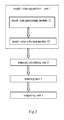
- FIG. 2 is a block diagram of a system for identifying an element parameters and a power correction factor of an electric power system according to the present invention
- FIG. 3 ( a ) is a circuit diagram of a CT
- FIG. 3 ( b ) is an equivalent circuit diagram of a CT
- FIG. 4 is an equivalent circuit diagram of an electric transmission line
- FIG. 5 is equivalent circuit diagram of a three-winding transformer.
- the method for identifying an element parameters and a power correction factor of an electric power system comprises the following steps in sequence:
- the telemetering values inputted to the electric power grid are obtained from an electric SCADA (Supervisory Control and Data Acquisition) system or are historical telemetering values of the SCADA.
- SCADA Supervisory Control and Data Acquisition
- Z O is an equivalent internal impedance of the CT
- Z L is an equivalent load of a secondary circuit of the CT
- I . 2 ′ Z O Z O + Z L ⁇ I . 2 , so
- n 1:
- said ⁇ circumflex over (P) ⁇ , ⁇ circumflex over (Q) ⁇ and ⁇ comprise: an active power telemetering steady state value ⁇ circumflex over (P) ⁇ c , a reactive power telemetering steady state value ⁇ circumflex over (Q) ⁇ c and a voltage telemetering steady state value ⁇ c corresponding to the element, for example: (a) for one line, an active power telemetering steady state value ⁇ circumflex over (P) ⁇ c , a reactive power telemetering steady state value ⁇ circumflex over (Q) ⁇ c and a voltage telemetering steady state value ⁇ c of two terminals of the line needs to be selected; (b) for a two-winding transformer, an active power telemetering steady state value ⁇ circumflex over (P) ⁇ c , a reactive power telemetering steady state value ⁇ circumflex over (Q) ⁇ c and a voltage telemetering steady state value ⁇ c of
- the admittance matrix Y of the element can be obtained by minimizing, and then the element parameters R,X,B can be restored through the relationship between the element admittance and the element parameters R,X,B.
- Y is an admittance matrix related to n elements
- ⁇ tilde over (Y) ⁇ is a conjugate matrix of Y
- ⁇ c is a conjugation of ⁇ c
- “.*” stands for multiplying the corresponding items
- n i is the number of elements connected to node i
- P ik is an active power telemetering correction value of element No. k connected to node i
- Q ik is a reactive power telemetering correction value of element No. k connected to node i
- N is the node number of a power grid.
- the elements parameters can be restored from the admittance matrix Y. Firstly the admittance matrix of each element is restored from Y, and then the element parameters R,X,B are restored through the relationship between the admittance matrix of each element and the element parameters R,X,B.
- FIG. 2 is a block diagram of a system for identifying an element parameters and a power correction factor of an electric power system according to the present invention, comprising:
- R is an equivalent resistance of the line
- X is a power frequency equivalent reactance of the line
- B is a power frequency equivalent susceptance of the line
- G is a power frequency equivalent conductance of the line.
- admittance matrix Y can be written out according to the equivalent circuit of a two-winding transformer:
- R is a copper resistance of a transformer
- X is a short-circuit reactance
- G is an iron-loss conductivity
- B is an exciting susceptance
- k is a non-standard ration of a transformer, and k can also be identified.
- R 1 is an equivalent resistance of winding 1
- X 1 is an equivalent reactance of winding 1
- R 2 is an equivalent resistance of winding 2
- X 2 is an equivalent reactance of winding 2
- k 12 is a non-standard ratio of winding 1 and winding 2
- R 3 is an equivalent resistance of winding 3
- X 3 is an equivalent reactance of winding 3
- k 13 is a non-standard ratio of winding 1 and winding 3
- G is an iron-loss equivalent conductivity of the transformer
- X m is an equivalent exciting reactance of the transformer, so:
- Y is an admittance matrix of the three-winding transformer, wherein:
- Y 11 [ 1 R + jX 1 0 0 0 1 R 2 + jX 2 ⁇ k 12 2 1 - k 12 0 0 0 1 R 3 + jX 3 ⁇ k 13 2 1 - k 13 ]
- ⁇ Y 21 [ - 1 R 1 + jX 1 ⁇ - 1 ( R 2 + jX 2 ) ⁇ k 12 ⁇ - 1 ( R 3 + jX 3 ) ⁇ k 13 ]
- ⁇ Y 12 Y 21 T
- Y 22 1 R 1 + jX 1 + 1 R 2 + jX 2 ⁇ k 12 k 12 - 1 + 1 R 3 + jX 3 ⁇ k 13 k 13 - 1 + G + 1 jX m .
- the admittance matrix Y of the three-winding transformer and the relationship between Y and the three-winding transformer parameters containing non-standard ratio can be obtained.
- R 1 , X i and B 1 are a resistance, a reactance and a susceptance of line 1
- R 2 , X 2 and B 2 are a resistance, a reactance and a susceptance of line 2
- R m and X m are a mutual resistance and mutual reactance of the double-circuit lines.
- equations of a multiple-circuit parallel transmission line can be written out after considering the mutual impedance, thereby obtaining admittance matrixes and the relationship between the admittance matrixes and the parameters.
- Y [ Y 11 0 0 Y 22 ] , where Y 11 is a admittance matrix of the line, referring to Eq.1 for details; Y 22 is a admittance matrix of the three-winding transformer, referring to Eq.4 for details; P, Q and U column vector are also partitioned:
- admittance matrixes of these elements are composed into diagonal elements of the partitioning matrixes, the off-diagonal elements are zero; correspondingly, P, Q, U column vectors can also be partitioned and arranged in order.
- the identified power correction factor ⁇ in the present invention can be used for online correcting for an telemetering active power value and an telemetering reactive power value, the ⁇ obtained by identification has already reckoned in influences of current transformer (CT) errors, potential transformer (PT) errors and reactive measurement formula, so that it is not necessary to consider further the reactive measurement errors.
- CT current transformer
- PT potential transformer
- the present invention also identifies element parameters as well, and by substituting the element parameters into online application equations, under coaction of the power correction factor ⁇ and the element parameters, the pass rate of state estimation and application precision such asstability analysis, stability check and stability control, etc. can be improved.
Abstract
Description
so
substituting it into formula S of an apparent power:
It can be seen, for the current transformer, the power error can be reflected by P+jQ=P′+jQ′+β·(P′+jQ′), where β is a power correction factor.
k=1, 2, . . . , N, where Pi is an active power injected to node i, Qi is a reactive power injected to node i, ni is the number of elements connected to node i, Pik is an active power telemetering correction value of element No. k connected to node i, Qik is a reactive power telemetering correction value of element No. k connected to node i, and N is the node number of a power grid.
so
setting F(Y,
{dot over (U)} 11 −{dot over (U)} 12=(R 1 +jX 1)·(İ 11 −{dot over (U)} 11 ·jB 1)+(R m +jX m)·(İ 21 −{dot over (U)} 21 ·jB 2)
{dot over (U)} 21 −{dot over (U)} 22=(R 2 +jX 2)·(İ 21 −{dot over (U)} 21 ·jB 2)+(R m +jX m)·(İ 11 −{dot over (U)} 11 ·jB 1)
İ 11 +İ 12 ={dot over (U)} 11 ·jB 1 +{dot over (U)} 12 ·jB 1
İ 21 +İ 22 ={dot over (U)} 21 ·jB 2 +{dot over (U)} 22 ·jB 2
where Y11 is a admittance matrix of the line, referring to Eq.1 for details; Y22 is a admittance matrix of the three-winding transformer, referring to Eq.4 for details; P, Q and U column vector are also partitioned:
where P1, Q1, U1 are P, Q, U column vectors of the line, referring to Eq.1 for details; P2, Q2 and U2 are P, Q, U column vectors of the three-winding transformer, referring to Eq.4 for details.
Claims (18)
G(β,{circumflex over (P)},{circumflex over (Q)})=βp1 ·{circumflex over (P)}+β p2 ·{circumflex over (Q)}+β p0 +j(βq1 ·{circumflex over (P)}+β q2 ·{circumflex over (Q)}+β q0),
β={βp1,βp2,βp0,βq1,βq2,βq0}.
G(β,{circumflex over (P)},{circumflex over (Q)})=β·({circumflex over (P)}+j{circumflex over (Q)}),β=βr +jβ m.
Applications Claiming Priority (4)
| Application Number | Priority Date | Filing Date | Title |
|---|---|---|---|
| CN201310382013 | 2013-08-28 | ||
| CN201310382013.5 | 2013-08-28 | ||
| CN201310382013.5A CN103441495B (en) | 2013-08-28 | 2013-08-28 | The discrimination method of power system component parameter and corrected coefficient of power and system |
| PCT/CN2014/081745 WO2015027756A1 (en) | 2013-08-28 | 2014-07-07 | Method and system for identifying element parameter and power correction factor of electric power system |
Publications (2)
| Publication Number | Publication Date |
|---|---|
| US20160226374A1 US20160226374A1 (en) | 2016-08-04 |
| US10367410B2 true US10367410B2 (en) | 2019-07-30 |
Family
ID=49695177
Family Applications (1)
| Application Number | Title | Priority Date | Filing Date |
|---|---|---|---|
| US14/914,957 Expired - Fee Related US10367410B2 (en) | 2013-08-28 | 2014-07-07 | Method and system for identifying power system element parameters and power correction factor |
Country Status (6)
| Country | Link |
|---|---|
| US (1) | US10367410B2 (en) |
| EP (1) | EP3041107A4 (en) |
| JP (1) | JP6172615B2 (en) |
| CN (1) | CN103441495B (en) |
| CA (1) | CA2922580C (en) |
| WO (1) | WO2015027756A1 (en) |
Families Citing this family (9)
| Publication number | Priority date | Publication date | Assignee | Title |
|---|---|---|---|---|
| CN103441495B (en) * | 2013-08-28 | 2015-07-29 | 三川电力设备股份有限公司 | The discrimination method of power system component parameter and corrected coefficient of power and system |
| CN104483836B (en) * | 2014-11-17 | 2017-08-29 | 国家电网公司 | A kind of online steady state process method of telemetry |
| CN106505557B (en) * | 2016-11-14 | 2023-11-14 | 中国电力科学研究院 | Remote measurement error identification method and device |
| CN107994586B (en) * | 2017-09-07 | 2021-04-27 | 国网山东省电力公司淄博供电公司 | High-voltage and low-voltage power grid voltage dynamic response decoupling method |
| WO2021229727A1 (en) * | 2020-05-13 | 2021-11-18 | 東芝三菱電機産業システム株式会社 | Physical model identification system |
| CN112147415B (en) * | 2020-09-27 | 2021-09-24 | 中国科学院地球化学研究所 | Method for measuring resistivity of metal iron sheet at high temperature and high pressure |
| CN112418701B (en) * | 2020-12-02 | 2022-10-25 | 广东电网有限责任公司广州供电局 | Power distribution network line equivalent resistance calculation method and device, terminal and storage medium |
| CN113360384B (en) * | 2021-06-12 | 2022-08-02 | 四川虹美智能科技有限公司 | App operation stability protection method and device and computer readable medium |
| CN116451505B (en) * | 2023-06-06 | 2023-09-05 | 中国电力科学研究院有限公司 | Power distribution network line parameter checking method, system, equipment and medium |
Citations (7)
| Publication number | Priority date | Publication date | Assignee | Title |
|---|---|---|---|---|
| JPH09114532A (en) | 1995-10-19 | 1997-05-02 | Hitachi Ltd | Voltage predicting method for reactive power controller |
| EP1381132A1 (en) | 2002-07-08 | 2004-01-14 | Abb Research Ltd. | Power network parameter estimation |
| US20080281474A1 (en) * | 2002-09-03 | 2008-11-13 | Patel Sureshchandra B | System of Super Super Decoupled Loadflow Computation for Electrical Power System |
| US20110185196A1 (en) * | 2010-01-25 | 2011-07-28 | Tomoyuki Asano | Power Management Apparatus, Electronic Appliance, and Method of Managing Power |
| CN102175922A (en) | 2011-01-24 | 2011-09-07 | 重庆大学 | Phasor measurement unit (PMU) measurement data-based power line parameter identification and estimation method |
| US20120109390A1 (en) * | 2010-10-29 | 2012-05-03 | Garth Delong | Method for integrating controls for captive power generation facilities with controls for metallurgical facilities |
| CN103217581A (en) | 2013-03-11 | 2013-07-24 | 河北省电力公司 | Method and system for achieving line parameter identification based on steady state telemetry technology |
Family Cites Families (7)
| Publication number | Priority date | Publication date | Assignee | Title |
|---|---|---|---|---|
| JP2566348B2 (en) * | 1991-06-26 | 1996-12-25 | 関西電力株式会社 | Positive line impedance measuring device for power lines |
| JP3317557B2 (en) * | 1992-12-21 | 2002-08-26 | 東京電力株式会社 | Transmission line constant measuring device and method for improving measurement accuracy |
| US7710729B2 (en) * | 2007-07-27 | 2010-05-04 | British Columbia Transmission Corporation | Method and system of real-time estimation of transmission line parameters in on-line power flow calculations |
| EP2378296B1 (en) * | 2010-04-19 | 2016-03-23 | ABB Technology AG | Method and arrangement for determining impedance values |
| CN102495288B (en) * | 2011-12-08 | 2013-10-30 | 重庆大学 | Method for identifying and estimating power transmission line parameters based on SCADA (Supervisory Control and Data Acquisition) measurement data |
| CN102946253B (en) * | 2012-10-23 | 2016-06-08 | 保定市三川电气有限责任公司 | Data sampling method and system and the application process in parameter identification thereof and system |
| CN103441495B (en) * | 2013-08-28 | 2015-07-29 | 三川电力设备股份有限公司 | The discrimination method of power system component parameter and corrected coefficient of power and system |
-
2013
- 2013-08-28 CN CN201310382013.5A patent/CN103441495B/en not_active Expired - Fee Related
-
2014
- 2014-07-07 WO PCT/CN2014/081745 patent/WO2015027756A1/en active Application Filing
- 2014-07-07 US US14/914,957 patent/US10367410B2/en not_active Expired - Fee Related
- 2014-07-07 EP EP14840089.8A patent/EP3041107A4/en not_active Withdrawn
- 2014-07-07 JP JP2016537099A patent/JP6172615B2/en not_active Expired - Fee Related
- 2014-07-07 CA CA2922580A patent/CA2922580C/en not_active Expired - Fee Related
Patent Citations (7)
| Publication number | Priority date | Publication date | Assignee | Title |
|---|---|---|---|---|
| JPH09114532A (en) | 1995-10-19 | 1997-05-02 | Hitachi Ltd | Voltage predicting method for reactive power controller |
| EP1381132A1 (en) | 2002-07-08 | 2004-01-14 | Abb Research Ltd. | Power network parameter estimation |
| US20080281474A1 (en) * | 2002-09-03 | 2008-11-13 | Patel Sureshchandra B | System of Super Super Decoupled Loadflow Computation for Electrical Power System |
| US20110185196A1 (en) * | 2010-01-25 | 2011-07-28 | Tomoyuki Asano | Power Management Apparatus, Electronic Appliance, and Method of Managing Power |
| US20120109390A1 (en) * | 2010-10-29 | 2012-05-03 | Garth Delong | Method for integrating controls for captive power generation facilities with controls for metallurgical facilities |
| CN102175922A (en) | 2011-01-24 | 2011-09-07 | 重庆大学 | Phasor measurement unit (PMU) measurement data-based power line parameter identification and estimation method |
| CN103217581A (en) | 2013-03-11 | 2013-07-24 | 河北省电力公司 | Method and system for achieving line parameter identification based on steady state telemetry technology |
Non-Patent Citations (4)
| Title |
|---|
| "Parameter identification of power system static load model based on field measurement", Dec. 31, 2001. |
| "Summary of power system model parameter identification", Dec. 31, 2010. |
| Chinese Search Report, dated Nov. 17, 2014, issued in corresponding Chinese Patent Application No. 201310382013.5. |
| International Search Report, dated Oct. 10, 2014, issued in corresponding International Application No. PCT/CN2014/081745. |
Also Published As
| Publication number | Publication date |
|---|---|
| CA2922580A1 (en) | 2015-03-05 |
| JP6172615B2 (en) | 2017-08-02 |
| JP2016530865A (en) | 2016-09-29 |
| CN103441495B (en) | 2015-07-29 |
| CN103441495A (en) | 2013-12-11 |
| EP3041107A4 (en) | 2017-05-03 |
| CA2922580C (en) | 2020-05-05 |
| EP3041107A1 (en) | 2016-07-06 |
| WO2015027756A1 (en) | 2015-03-05 |
| US20160226374A1 (en) | 2016-08-04 |
Similar Documents
| Publication | Publication Date | Title |
|---|---|---|
| US10367410B2 (en) | Method and system for identifying power system element parameters and power correction factor | |
| Abur et al. | Power system state estimation: theory and implementation | |
| Swetapadma et al. | Improved fault location algorithm for multi‐location faults, transforming faults and shunt faults in thyristor controlled series capacitor compensated transmission line | |
| Shi et al. | Identification of short transmission-line parameters from synchrophasor measurements | |
| US9989580B2 (en) | Fault analysis in electric networks having a plurality of multi-phase buses | |
| RU2562931C2 (en) | Method and device for localisation of fault to ground | |
| Jiang et al. | Identification of voltage stability critical injection region in bulk power systems based on the relative gain of voltage coupling | |
| CN102132163A (en) | Fault locating method and fault locating apparatus | |
| CN104112239A (en) | Method and device for transformer state assessment based on benchmark state analysis | |
| CN106228459A (en) | Equivalent reliability estimation method based on Monte Carlo | |
| CN103529388B (en) | A kind of method and device measuring difference modulation rate of power generation set | |
| CN107167689B (en) | Consider the probabilistic short circuit sensitivity computing method of connecting transformer no-load voltage ratio | |
| CN107832959A (en) | A kind of voltage stability assessment method for considering part throttle characteristics and power constraints | |
| CN115085368A (en) | Transformer health state monitoring method and device, computer equipment and storage medium | |
| CN105203877A (en) | Single-loop power transmission line zero sequence parameter identification method capable of eliminating measurement error influences | |
| US20210063463A1 (en) | Fault Location in Multi-Terminal Tapped Lines | |
| Gupta et al. | Three phase current transformer calibration without external reference it using synchrophasors: An SVD approach | |
| CN112578188B (en) | Method, device, computer equipment and storage medium for generating electric quantity waveform | |
| CN103795056B (en) | Based on the crucial branch road recognition methods of the electrical network mapping elastic potential energy | |
| CN112886579A (en) | Power distribution network line parameter identification method considering unmatched PMU and SCADA measurement time scales | |
| Hebling et al. | Sparse and orthogonal method for fast bad data processing in distribution system state estimation | |
| Ren et al. | Generic algorithm to calculate Jacobian matrix used for ladder network parameters identification and winding fault diagnosis | |
| Ashraf et al. | Voltage stability monitoring using reduced network and measurement transformation | |
| CN103197557A (en) | Real-time monitoring closed-loop control system and working method thereof | |
| Qin et al. | A Method for Distribution Line Impedance Calculation Based on Metering and Distribution Data Integration |
Legal Events
| Date | Code | Title | Description |
|---|---|---|---|
| STPP | Information on status: patent application and granting procedure in general |
Free format text: NOTICE OF ALLOWANCE MAILED -- APPLICATION RECEIVED IN OFFICE OF PUBLICATIONS |
|
| STPP | Information on status: patent application and granting procedure in general |
Free format text: PUBLICATIONS -- ISSUE FEE PAYMENT VERIFIED |
|
| STCF | Information on status: patent grant |
Free format text: PATENTED CASE |
|
| FEPP | Fee payment procedure |
Free format text: MAINTENANCE FEE REMINDER MAILED (ORIGINAL EVENT CODE: REM.); ENTITY STATUS OF PATENT OWNER: SMALL ENTITY |
|
| LAPS | Lapse for failure to pay maintenance fees |
Free format text: PATENT EXPIRED FOR FAILURE TO PAY MAINTENANCE FEES (ORIGINAL EVENT CODE: EXP.); ENTITY STATUS OF PATENT OWNER: SMALL ENTITY |
|
| STCH | Information on status: patent discontinuation |
Free format text: PATENT EXPIRED DUE TO NONPAYMENT OF MAINTENANCE FEES UNDER 37 CFR 1.362 |
|
| FP | Lapsed due to failure to pay maintenance fee |
Effective date: 20230730 |